


134 Radio Engineering for Wireless Communication and Sensor Applications
direction of propagation. The electric field is now parallel to the resistive card at the output (output for reverse direction) and the wave is absorbed.
6.2.4 Circulators
An ideal circulator is an n -port device, which passes a signal applied in port 1 to port 2, a signal applied in port 2 to port 3, and finally a signal applied in port n to port 1. Usually, a circulator has three ports.
A three-port circulator can be used as an isolator by terminating one of the ports with a matched load. Circulators are used to separate the input and output ports of such devices that are based on reflection (e.g., reflection amplifier). Circulators are also used in radars to couple the transmitted power to the antenna and the echo signals from the antenna to the receiver.
A circulator may be based on the Faraday rotation or on a directiondependent phase shift. The Y-junction circulator is the most common type. A cylindrical ferrite is placed in the middle of a symmetric junction, as shown in Figure 6.17. A static magnetic field is along the axis of the cylinder. The operation of this circulator may be explained by two degenerate resonance modes whose resonance frequencies differ due to the magnetic field [4, 5]. The operation range is between these two resonance frequencies.
6.3 Other Passive Components and Devices
In addition to the reciprocal power dividers and directional couplers and nonreciprocal ferrite devices, many other passive devices and components
Figure 6.17 Y-junction circulator.
Passive Transmission Line and Waveguide Devices |
135 |
are needed in radio engineering. Terminations, attenuators, phase shifters, connectors, and adapters are briefly discussed here.
6.3.1 Terminations
Terminations are single-port components that are used for terminating transmission lines, waveguides, and ports of different devices. Matched loads (in an ideal case r = 0), shorts or short circuits ( r = −1), and open ends or open circuits ( r = +1) are terminations that are commonly used in measurements and in the calibration of measurement equipment.
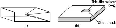
A matched load absorbs all the power that is incident on it. Therefore, the impedance of a matched load equals the characteristic impedance of the line it terminates. A matched load can be realized by inserting a wedge, card, or pyramid made of lossy material in the waveguide, as shown in Figure 6.18(a). The length of the load should be at least one wavelength. A matched load is often adjustable; that is, the position of the absorber can be adjusted. Then, in measurements requiring a good accuracy, we may eliminate the effect of reflection from a nonideal matched load by performing the measurements with several positions of the load. A good matched load may have a VSWR less than 1.01. In a microstrip line, a matched load can be realized by terminating the line with a thin-film resistor followed by a shorting pin, as illustrated in Figure 6.18(b).
An ideal short circuit reflects the incident power totally. As a matched load, a short also may be fixed or adjustable. With an adjustable short we can realize a desired reactance: The impedance in a lossless line at a distance of l from the short is
Z = jZ 0 tan b l |
(6.39) |
A metal block tightly fit in a coaxial line or waveguide serves as a simple short. However, in such a short the contact between the line and metal block is erratic if the short is moved. Figure 6.19 shows a structure
Figure 6.18 Matched loads: (a) in waveguide; and (b) in microstrip line.
136 Radio Engineering for Wireless Communication and Sensor Applications
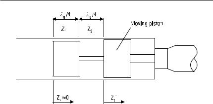
Figure 6.19 Adjustable short.
that is better suited for an adjustable short. It is made of highand lowimpedance quarter-wave sections that operate as impedance inverters. If the characteristic impedances of the low-impedance and high-impedance sections are Z 1 and Z 2 , respectively, the input impedance is
|
SZ 2 D |
|
|
|
2 |
|
|
Z s = |
Z 1 |
Z s′ |
(6.40) |
|
where Z s′ is the impedance indicated in Figure 6.19. Thus Z s is much lower than Z s′, which already has a low value. The disadvantage of this short is its narrow bandwidth, about 10%; the length of the sections is a quarter wavelength only at a single frequency.
Often an open-ended line does not correspond well to an ideal open circuit. The fringing fields of an open end of a coaxial line may be modeled as a small capacitor or as an extension of the line. An open-ended waveguide radiates effectively and operates as an antenna; thus, it does not resemble an open circuit at all. An open-ended microstrip line is quite a good open circuit; it only needs to be slightly shortened to compensate for the length extension due to a fringing field.
6.3.2 Attenuators
An ideal attenuator passes a given part of the incident power, absorbs the rest, and has matched ports. Lowering a power level, improving impedance matching, and measuring power ratios are applications of attenuators. The value of attenuation may be fixed or adjustable.
Passive Transmission Line and Waveguide Devices |
137 |
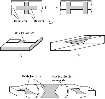
Figure 6.20(a) shows two fixed coaxial attenuators made of seriesconnected and parallel-connected resistors in a T and p configuration. In a microstrip circuit, T and p attenuators can be realized with the same principle using thin-film resistors. Figure 6.20(b) shows a simple microstrip line attenuator. The waveguide attenuator shown in Figure 6.20(c) has a resistive card in the middle of the broad wall along the direction of the E field. The card is tapered to ensure good matching.
Figure 6.21 shows a continuously adjustable waveguide attenuator. It has a rotating, circular waveguide section between a rectangular input and output waveguide. All three sections contain thin resistive cards. The input signal passes the first card with a negligible attenuation because the electric field of the TE10 wave mode is perpendicular to the card. Then the wave enters through a transition to the circular waveguide. The attenuation is adjusted by rotating the circular waveguide section and the resistive card within it. The field of the TE11 wave mode can be divided into two compo-
Figure 6.20 Fixed attenuators: (a) coaxial attenuators, T- and p -type; (b) microstrip attenuator; and (c) waveguide attenuator.
Figure 6.21 Adjustable waveguide attenuator.