


feedback control - 8.24
Figure 8.33 A state based feedforward controller
8.3.8 Cascade Controllers
When controlling a multistep process a cascade controller can allow refined control of sub-loops within the larger control system. Most large processes will have some form of cascade control. For example, the inner loop may be for a heating oven, while the outer loop controls a conveyor feeding parts into the oven.
|
|
|
|
|
|
|
|
|
|
|
|
|
|
|
|
|
|
|
|
|
|
|
|
|
|
|
|
|
|
|
|
|
|
|
|
|
|
|
|
|
|
|
|
|
|
|
|
|
|
|
|
|
|
|
|
|
|
|
|
|
|
|
|
|
|
|
|
|
|
|
|
|
|
|
|
|
|
|
|
|
|
|
|
|
|
|
|
|
|
Gc1 |
|
|
|
|
|
|
|
|
|
|
|
|
|
Gc2 |
|
|
|
|
|
|
|
|
|
|
|
|
|
|
|
Gp1 |
|
|
|
|
|
|
|
Gp2 |
|
|
|
|
|
|
|
|
|
|
|||||||||||||||
|
|
|
|
|
|
|
|
|
|
|
|
|
|
|
|
|
|
|
|
|
|
|
|
|
|
|
|
|
|
|
|
|
|
|
|
|
|
|
|
|
|
|
|
|
|
|
|
|
|
|
|
|
|
|
|
|
|
|||||||||||||||||||
|
|
|
|
|
|
|
|
|
|
|
|
|
|
|
|
|
|
|
|
|
|
|
|
|
|
|
|
|
|
|
|
|
|
|
|
|
|
|
|
|
|
|
|
|
|
|
|
|
|
|
|
|
|
|
|
|
|
|||||||||||||||||||
|
|
|
|
|
|
|
|
|
|
|
|
|
|
|
|
|
|
|
|
|
|
|
|
|
|
|
|
|
|
|
|
|
|
|
|
|
|
|
|
|
|
|
|
|
|
|
|
|
|
|
|
|
|
|
|
|
|
|||||||||||||||||||
|
|
|
|
|
|
|
|
|
|
|
|
|
|
|
|
|
|
|
|
|
|
|
|
|
|
|
|
|
|
|
|
|
|
|
|
|
|
|
|
|
|
|
|
|
|
|
|
|
|
|
|
|
|
|
|
|
|
|||||||||||||||||||
|
|
|
|
|
|
|
|
|
|
|
|
|
|
|
|
|
|
|
|
|
|
|
|
|
|
|
|
|
|
|
|
|
|
|
|
|
|
|
|
|
|
|
|
|
|
|
|
|
|
|
|
|
|
|
|
|
|
|
|
|
|
|
|
|
|
|
|
|
|
|
|
|
|
|
|
|
|
|
|
|
|
|
|
|
|
|
|
|
|
|
|
|
|
|
|
|
|
|
|
|
|
|
|
|
|
|
|
|
|
|
|
|
|
|
|
|
|
|
|
|
|
|
|
|
|
|
|
|
|
|
|
|
|
|
|
|
|
|
|
|
|
|
|
|
|
|
|
|
|
|
|
|
|
|
|
|
|
|
|
|
|
|
|
|
|
|
|
|
|
|
|
|
|
|
|
|
|
|
|
|
|
|
|
|
|
|
|
|
|
|
|
|
|
|
|
|
|
|
|
|
|
|
|
|
|
|
|
|
|
|
|
|
|
|
|
|
|
|
|
|
|
|
|
|
|
|
|
|
|
|
|
|
|
|
|
|
|
|
|
|
|
|
|
|
|
|
|
|
|
|
|
|
|
|
|
|
|
|
|
|
|
|
|
|
|
|
|
|
|
|
|
|
|
|
|
|
|
|
|
|
|
|
|
|
|
|
|
|
|
|
|
|
|
|
|
|
|
|
|
|
|
|
|
|
|
|
|
|
|
|
|
|
|
|
|
|
|
|
|
|
|
|
|
|
|
|
|
|
|
|
|
|
|
|
|
|
|
|
|
|
|
|
|
|
|
|
|
|
|
|
|
|
|
|
|
|
|
|
|
|
|
|
|
|
|
|
|
|
|
|
|
|
|
|
|
|
|
|
|
|
|
|
|
|
|
|
|
|
|
|
|
|
|
|
|
|
|
|
|
|
|
|
|
|
|
|
|
|
|
|
|
|
|
|
|
|
|
|
|
|
|
|
|
|
|
|
|
|
|
|
|
|
|
|
|
|
|
|
|
|
|
|
|
|
|
|
|
|
|
|
|
|
|
|
|
|
|
|
|
|
|
|
|
|
|
|
|
|
|
|
|
|
|
|
|
|
|
|
|
|
|
|
|
|
|
|
|
|
|
|
|
|
|
|
|
|
|
|
|
|
|
|
|
|
|
|
|
|
|
|
|
|
|
|
|
|
|
|
|
|
|
|
|
|
|
|
|
|
|
|
|
|
|
|
|
|
|
|
|
|
|
|
|
|
|
|
|
|
|
|
|
|
|
|
|
|
|
|
|
|
|
|
|
|
|
|
|
|
|
|
|
|
|
|
|
|
|
|
|
|
|
|
|
|
|
|
|
|
|
|
|
|
|
|
|
|
|
|
|
|
|
|
|
|
|
|
|
|
|
|
|
|
|
|
|
|
|
|
|
|
|
|
|
|
|
|
|
|
|
|
|
|
|
|
|
|
|
|
|
|
|
|
|
|
|
|
|
|
|
|
|
|
|
|
|
|
|
|
|
|
|
|
|
|
|
|
|
|
|
|
|
|
|
|
|
|
|
|
|
|
|
|
|
|
|
|
|
|
|
|
|
|
|
|
|
|
|
|
|
|
|
|
|
|
|
|
|
|
|
|
|
|
|
|
|
|
|
|
|
|
|
|
|
|
|
|
|
|
|
|
|
|
|
|
|
|
|
|
|
|
|
|
|
|
|
|
|
|
|
|
|
|
|
|
|
|
|
|
|
|
|
|
|
|
|
|
|
|
|
|
|
|
|
|
|
|
|
|
|
|
|
|
|
|
|
|
|
|
|
|
|
|
|
|
|
|
|
|
|
|
|
|
|
|
|
|
|
|
|
|
|
|
|
|
|
|
|
|
|
|
|
|
|
|
|
|
|
|
|
|
|
|
|
|
|
|
|
|
|
|
|
|
|
|
|
|
|
|
|
|
|
|
|
|
|
|
|
|
|
|
|
|
|
|
|
|
|
|
|
|
|
|
|
|
|
|
|
|
|
|
|
|
|
|
|
|
|
|
|
|
|
|
|
|
|
|
|
|
|
|
|
|
|
|
|
|
|
|
|
|
|
|
|
|
|
|
|
|
|
|
|
|
|
|
|
|
|
|
|
|
|
|
|
|
|
|
|
|
|
|
|
|
|
|
|
|
|
|
|
|
|
|
|
|
|
|
|
|
|
|
|
|
|
|
|
|
|
|
|
|
|
|
|
|
|
|
|
|
|
|
|
|
|
|
|
|
|
|
|
|
|
|
|
|
|
|
|
|
|
|
|
|
|
|
|
|
|
|
|
|
|
|
|
|
|
|
|
|
|
|
|
|
|
|
|
|
|
|
|
|
|
|
|
|
|
|
|
|
|
|
|
|
|
|
|
|
|
|
|
|
|
|
|
|
|
|
|
|
|
|
|
|
|
|
|
|
|
|
|
|
|
|
|
|
|
|
|
|
|
|
|
|
|
|
|
|
|
|
|
|
|
|
|
|
|
|
|
|
|
|
|
|
|
|
|
|
|
|
|
|
|
|
|
|
|
|
|
|
|
|
|
|
|
|
|
|
|
|
|
|
|
|
|
|
|
|
|
|
|
|
|
|
|
|
|
|
|
|
|
|
|
|
|
|
Figure 8.34 A cascade controller
8.4SUMMARY
•Transfer functions can be used to model the ratio of input to output.
•Block diagrams can be used to describe and simplify systems.
•Controllers can be designed to meet criteria, such as damping ratio and natural frequency.
•System errors can be used to determine the long term stability and accuracy of a controlled system.
•Other control types are possible for more advanced systems.
8.5PRACTICE PROBLEMS
1.Develop differential equations and then transfer functions for the mechanical system below. There is viscous damping between the block and the ground. A force is applied to cause the

feedback control - 8.26
4. Find the transfer functions for the system below where Vi is the input and Vo is the output.
|
|
C |
|
L |
|
|
|||
|
|
|
|
|
|
|
|
|
|
|
|
|
|
|
|
|
|
|
|
+ |
|
|
|
|
|
|
|
+ |
|
|
|
|
|
|
|
||||
Vi |
|
|
R1 |
|
|
R2 |
|
Vo |
|
- |
|
|
|
|
|
|
- |
||
|
|
|
|
|
|
|
|
|
|
5. Given the transfer function, G(s), determine the time response output Y(t) to a step input X(t).
G = |
4 |
= |
Y |
X( t) = 20 When t >= 0 |
D-------------+ 2 |
-- |
|||
|
|
X |
|
6.Given the transfer function below, develop a mechanical system that it could represent. (Hint: Differential Equations).
------------x( D) |
= |
----------------------1 |
where: x = displacement |
F( D) |
|
10 + 20D |
F = force |
7.Given a mass supported by a spring and damper, find the displacement of the supported mass over time if it is released from neutral at t=0sec, and gravity pulls it downward.
a)develop a transfer function for y/F.
b)find the input function F.
c)solve the input output equation to find an explicit equation of the position as a function of time for Ks = 10N/m, Kd = 5Ns/m, M=10kg.
d)solve part c) numerically.
8.a) What is a Setpoint, and what is it used for? b) What does feedback do in control systems?
9.The block diagram below is for a servo motor position control system. The system uses a proportional controller.
a)Draw a sketch of what the actual system might look like. Identify components.
θ d |
|
|
Vd |
Ve |
|
Vm |
|
|
|
ω |
|
|
|
|
θ a |
||||||
|
|
|
10 rad |
|
1 |
||||||||||||||||
|
|
|
2 |
V |
|
|
|
|
|
K |
|
|
D-------------+ 1 --------sV |
|
|
|
--- |
|
|
|
|
|
|
|
rad-------- |
+ |
|
|
|
|
|
|
|
|
|
|
D |
|
|
|
|||
|
|
|
|
|
|
|
|
|
|
|
|
|
|
|
|
|
|
|
|
|
|
|
|
|
|
|
- |
|
|
|
|
|
|
|
|
|
|
|
|
|
|
|
|
|
|
|
|
|
|
|
|
|
|
|
|
|
|
|
|
|
|
|
|
|
|
|
|
|
|
|
|
Va |
|
|
|
|
|
|
V |
|
|
|
|
|
|
|
|
|
|
|
|
|
|
|
|
|
|
|
|
|
|
|
|
|
|
|
|
||
|
|
|
|
|
|
|
|
|
|
|
|
|
2rad-------- |
|
|
|
|
|
|
|
|
b) Convert the system to a transfer function.
feedback control - 8.27
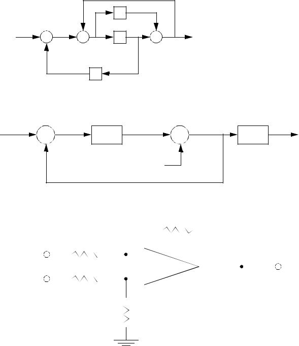
10. Simplify the block diagram below to a transfer function.
|
|
A |
|
|
+ |
|
- |
+ |
+ |
|
|
|||
|
B |
y |
||
x |
|
|
||
|
- |
+ |
|
|
|
|
|
|
|
|
|
C |
|
|
11. Simplify the block diagram below. (Note: Vn is an input and cannot be combined in a transfer function.)
+ |
+ |
|
A |
C |
Vo |
Vi |
|
|
- |
+ |
|
|
Vn |
|
12. a) Develop an equation for the system below relating the two inputs to the output. Put it in block diagram format. (Hint: think of a summation block.)
|
|
R |
|
|
|
R |
|
|
|
|
Vf |
|
|
|
|
|
|
|
|
|
|
|
R |
|
|
- |
|
|
|
|
Ve |
|
|
|
|
||||||||
Vd |
|
|
|
+ |
|
|
|
|
||
|
|
|
|
|
|
|||||
|
|
|
|
|
|
|
|
|
||
|
|
|
||||||||
R
b)Develop an equation for the system below relating the input to the output. Put

feedback control - 8.28
the result in block diagram format.
|
|
|
1K |
|
|
|
1K |
|
|
|
|
|
|
|
|
|
|
|
|
|
|
|
|
Ve |
|
|
1K |
|
|
- |
|
|
|
|
Vs |
|
|
|
|
||||||||
|
|
|
|
+ |
|
|
|
|
|||
|
|
|
|
|
|
||||||
|
|
|
|
|
|
|
|
|
|
||
|
|
|
|
||||||||
|
|
|
|
|
|
|
|
|
|
|
|
RP
c)The equation below can be used to model a permanent magnet DC motor with an applied torque. An equivalent block diagram is given. Prove that the block diagram is equivalent to the equation.
d |
|
ω +ω |
|
Km2 |
|
|
Km |
– |
Tload |
|
|
|||||
|
|
|
|
= Vs |
|
|
|
----------- |
|
|
|
|||||
---- |
|
|
|
------------ |
|
|
------------ |
|
|
|
|
|||||
dt |
|
|
JRRM |
|
|
JRRM |
|
JR |
|
|
||||||
Vs |
|
|
|
|
|
+ |
|
|
|
e |
|
|
|
|
ω |
|
|
|
|
Km |
|
|
|
|
|
|
RM |
|
|||||
|
|
|
|
|
|
|
|
|
|
|
||||||
|
|
|
|
|
------ |
|
|
|
|
|
|
|
|
--------------------------------- |
|
|
|
|
|
|
|
RM |
|
|
|
|
|
|
|
2 |
|
|
|
|
|
|
|
|
|
- |
|
|
|
|
|
JRRMD + Km |
|
|
||
|
|
|
|
|
|
|
|
|
|
|
|
|
|
|||
|
|
|
|
|
|
|
|
|
|
|
|
|
|
|
|
|
Tload
d)Write the transfer function for the system below relating the input torque to the output angle theta2. Then write the transfer function for the angular velocity of
mass 2.
|
θ |
1 |
θ |
2 |
τ |
Ks1 |
J1 |
Ks2 |
J2 |
|
|
|||
|
|
|
|
B |
e) The system below is a combination of previous components, and a tachometer |
||||

feedback control - 8.29
for velocity feedback. Simplify the block diagram.
Vd |
|
|
|
|
|
|
|
|
|
|
|
|
|
|
|
ω |
||
|
|
|
2RP |
|
|
Km |
|
+ |
----------------------------------RM |
|
||||||||
|
|
|
|
|
|
|
|
|
|
|
2 |
|
|
|||||
|
+ |
|
|
|
-------------------- |
|
------ |
|
|
|
|
|
JMRMD + Km |
|
|
|||
|
|
|
RP + 103 |
|
|
RM |
|
|
|
|
|
|
|
|
||||
|
|
|
- |
|
|
|
|
|
|
- |
|
|
|
|
|
|||
|
|
|
|
|
|
|
|
|
|
|
|
|
|
|||||
|
|
|
|
|
|
|
|
|
|
|
|
|
|
|
|
|
||
|
|
|
|
|
|
|
|
|
|
|
|
|
|
|||||
Ks2
-----------------------------------------------------------------------------------------------------------------------
D3( J1J2) + D2( BJ1) + D( Ks2( J1 + J2) ) + ( BKs2)
KT
13. Find the system output, feedback error and system error when the input is a ramp with the function c(t) = 0.5t. Sketch the system errors as a function of time.
C( D) |
+ |
|
|
|
|
|
|
|
R( D) |
||
|
|
|
|
5 |
|||||||
|
|
|
|
|
|
|
---------------------- |
|
|
|
|
|
|
|
- |
|
|
|
D( D + 1) |
|
|
|
|
|
|
|
|
|
|
|
|
|
|
|
|
|
|
|
|
|
|
|
|
||||
|
|
|
|
|
|
|
|
|
|
|
|
|
|
|
|
|
|
|
|
|
|
|
|
|
|
|
|
|
|
|
1 + 0.2D |
|
|
|
|
|
|
|
|
|
|
|
|
|
|
|
|
|
|
|
|
|
|
|
|
|
|
|
|
14. Given the block diagram below, select a system gain K that will give the overall system a damping ratio of 0.7 (for a step input). What is the resulting damped frequency of the system?
+ |
2 |
K |
----------------------------- |
|
D2 + 3D + 2 |
- |
|
15. The following system is a feedback controller for an elevator. It uses a desired height ‘d’ provided by a user, and the actual height of the elevator ‘h’. The difference between these two is called the error ‘e’. The PID controller will examine the value ‘e’ and then control the speed of the lift motor with a control voltage ‘c’. The elevator and controller are described with transfer functions, as shown below. all of these equations can be combined into a single system transfer

|
|
|
|
|
|
|
|
|
|
|
|
|
|
|
|
|
|
feedback control - 8.30 |
|
|
|
|
|
|
||||
equation as shown. |
|
|
|
|
|
|
|
|
|
|
|
|
|
|
|
|
|
|||||||||||
|
|
e = |
d – h |
|
error |
|
|
|
|
|
|
|
|
|
|
|
|
|
|
|
|
|||||||
|
r |
|
|
|
|
Ki |
|
|
|
|
|
|
2D + 1 + D |
2 |
PID controller |
|
h |
= |
10 |
elevator |
||||||||
|
|
|
|
|
+ KdD = |
|
|
-- |
D----------------2 + D |
|||||||||||||||||||
|
- |
= Kp + ---- |
----------------------------- |
|
D |
|
|
|
|
|
r |
|
|
|||||||||||||||
|
e |
|
|
|
|
|
D |
|
|
|
|
|
|
|
|
|
|
|
|
|
|
|
|
|
|
|||
|
|
combine the transfer functions |
|
|
|
|
|
|
|
|
|
|
||||||||||||||||
|
r |
|
h |
|
|
h 2D + 1 + D2 10 |
|
|
( D + 1) 2 10 |
|
10( D + 1) |
|
|
|||||||||||||||
|
|
= |
-- |
= |
|
|
|
|
|
|
|
|
|
|
|
= |
|
|
= |
|
|
|
|
|
||||
|
- |
|
-- |
|
----------------------------- |
|
|
D |
---------------- |
|
2 |
|
|
-------------------- |
D D----------------------( D + 1) |
------------------------ |
2 |
|
|
|
||||||||
e r |
|
|
e |
|
|
|
|
|
D |
+ D |
|
|
|
|
D |
|
|
|
||||||||||
|
|
|
|
|
|
|
10( D + 1) |
|
|
|
|
|
|
|
|
|
|
|
||||||||||
|
|
|
|
h |
|
|
|
|
|
|
|
|
|
|
eliminate ‘e’ |
|
|
|
|
|
|
|||||||
|
|
d – h = |
|
|
|
|
2 |
|
|
|
|
|
|
|
|
|
|
|
|
|
|
|
|
|||||
|
|
------------------------ |
|
D |
|
|
|
|
|
|
|
|
|
|
|
|
|
|
|
|
|
|||||||
|
|
h |
= |
10( D + 1) |
( d – h) |
|
|
|
|
|
|
|
|
|
|
|
|
|
||||||||||
|
|
------------------------ |
|
D2 |
|
|
|
|
|
|
|
|
|
|
|
|
|
|
|
|||||||||
|
|
|
|
|
|
|
|
|
|
|
|
|
|
|
|
|
|
|
|
|
|
|
|
|||||
|
|
h |
|
1 + |
10( D + 1) |
|
= |
|
10( D + 1) |
( d) |
|
|
|
|
|
|
|
|
||||||||||
|
|
|
------------------------ |
|
D2 |
|
|
|
|
------------------------D2 |
|
|
|
|
|
|
|
|
||||||||||
|
|
|
|
|
|
|
|
|
|
|
|
|
|
|
|
|
|
|
|
|||||||||
|
|
|
|
|
|
10( D + 1) |
|
|
|
|
|
|
|
|
|
|
|
|
|
|
|
|
||||||
|
|
|
|
|
|
|
------------------------ |
|
|
|
|
|
|
|
|
|
|
|
|
|
|
|
|
|||||
|
|
h |
= |
|
|
D2 |
|
|
= |
|
10D + 10 |
system transfer function |
|
|||||||||||||||
|
|
-- |
|
--------------------------------- |
|
10( D + 1) |
|
|
|
|
|
|
|
|
||||||||||||||
|
|
d |
|
|
|
+ |
|
D |
2 |
+ 10D + 10 |
|
|
|
|
|
|
|
|||||||||||
|
|
|
|
|
1 |
------------------------ |
|
D2 |
|
|
|
|
|
|
|
|
|
|
|
|||||||||
|
|
|
|
|
|
|
|
|
|
|
|
|
|
|
|
|
|
|
|
|
|
|
|
|
|
|
||
a)Find the response of the final equation to a step input. The system starts at rest on the ground floor, and the input (desired height) changes to 20 as a step input.
b)Calculate the damping coefficient and natural frequency of the results in part a).
16.Study the circuit below. Assume that for t<0s the circuit is discharged and off. Starting at t=0s an input of Vi=5sin(100,000t) is applied.
1K
+ Vi -
+
1uF
Vo
-
a)Write a differential equation and then a transfer function describing the circuit.
b)Find the output of the circuit using explicit integration (i.e., homogeneous and particular solutions).
17.Write a C subroutine to implement the control system that is shown inside the dashed line. The subroutine arguments are the setpoint, C, and the feedback value, F. the subroutine returns the