

circuits - 7.32
Figure 7.36 Typical supply voltages
7.6 FILTERS
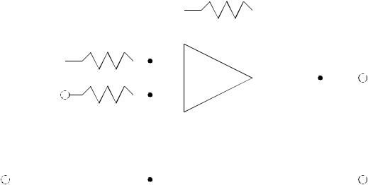
Filters are useful when processing data signals. Low pass often used to eliminate noise, high pass filters eliminate static signals and leave dynamic signals. Band pass filters reject all frequencies outside a desired frequency band. A low pass filter is shown in Figure 7.37. At high frequencies the capacitor, C, has a very low impedance, and grounds the input signal. At low frequencies the capacitor impedance is high, increasing the gain of the op-amp circuit. This is easier to conceptualize if the R1-C pair are viewed as a voltage divider.
Rf
|
|
|
|
|
|
|
Ri |
|
|
|
|
|
|
|
|
|
|
|
|
|
|
|
|
|
|
|
|
|
|
|
|
|
|
|
|
|
|
|
|
|
|
|
|
|
|
|
|
|
|
|
|
|
- |
|
|
|
|
|
|
|
|
|
|
|
|
|
|
|
|
|
|
|
|
|
|
|
|
|
|
|
|
|
|
|
|
+ |
|
|
|
|||||
|
|
|
|
|
|
|
|
|
|
|
|
|||||||
|
|
|
|
|
|
|
R1 |
|
|
+ |
||||||||
+ |
|
|
|
|
|
|
|
|
|
|
Vo |
|||||||
|
|
|
|
|
|
|
|
|
||||||||||
|
|
|
|
|
|
|
|
|
|
|
|
|
- |
|||||
|
|
|
|
|
|
Vi |
|
|
|
C |
||||||||
- |
|
|
|
|
|
|
|
|
|
|
|
|||||||
|
|
|
|
|
|
|
|
|
|
|
|
|
|
|
|
|
|
|
|
|
|
|
|
|
|
|
|
|
|
|
|
|
|
|
|
|
|
|
|
|
|
|
|
|
|
|
|
|
|
|
|
|
|
|
|
|
|
|
|
|
|
|
|
|
|
|
|
|
|
|
|
|
|
|
|
Figure 7.37 Low-Pass Filter
A high pass filter is shown in Figure 7.38. In this case the voltage divider in the previous circuit is reversed. In this circuit the gain will increase for signals with higher frequencies.

circuits - 7.33
Rf
Ri
-
+
|
C |
|
|
+ |
|||||||
|
|||||||||||
+ |
|
|
|
|
|
|
|
|
|
|
Vo |
Vi |
- |
||||||||||
|
|
R |
|||||||||
- |
|
|
|
|
|
|
|
|
|
|
|
|
|
|
|
|
|
|
|
|
|
|
|
|
|
|
|
|
|
|
|
|
|
|
|
|
|
|
|
|
|
|
|
|
|
|
|
|
|
|
|
|
|
|
|
|
|
|
|
Figure 7.38 High-Pass Filter
7.7 OTHER TOPICS
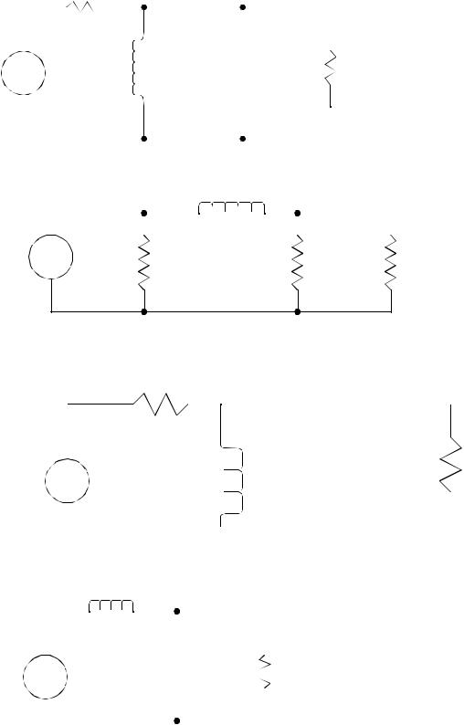
The relationships in Figure 7.39 can be used to calculate the power and energy in a system. Notice that the power calculations focus on resistance, as resistances will dissipate power in the form of heat. Other devices, such as inductors and capacitors, store energy, but don’t dissipate it.
P = IV = I |
2 |
R = |
V2 |
E = Pt |
|
----- |
|||
|
|
|
R |
|
Figure 7.39 Electrical power and energy
7.8SUMMARY
•Basic circuit components are resistors, capacitors, inductors op-amps.
•node and loop methods can be used to analyze circuits.

circuits - 7.34
•Capacitor and inductor impedances can be used as resistors in calculations.
7.9PRACTICE PROBLEMS
1.Derive the equations for combined values for resistors, capacitors and inductors in series and parallel.
2.Find the output voltage as a function of input voltage.
|
|
R |
R |
||||
Vi |
|
|
|
|
|
|
+ |
|
|
|
|
|
|
||
|
|
|
|
|
|
|
|
+ |
|
|
|
|
|
Vo |
|
|
|
|
|
|
|
||
|
- |
|
R |
|
|
||
|
|
|
R |
||||
-
3. Write the differential equation for the following circuit.
|
L |
|
R |
|
|
|
||
|
|
|
|
|
|
|
||
Vi |
|
|
|
|
|
|
+ |
|
|
|
|
|
|
|
|||
|
|
|
|
|
|
|
|
|
|
|
|
|
|
|
|
|
|
+ |
|
|
|
|
C |
|
|
Vo |
- |
|
|
|
|
|
|
||
|
|
|
|
|||||
-
4. Consider the following circuit.
|
|
L |
|
|
|
|
+ |
|
|
|
|
|
|
|
|
|
|
Vi + |
|
C |
|
|
|
|
Vo |
|
|
|
|
|
|
||||
- |
|
|
|
|
|
|
||
|
|
|
|
R |
||||
|
|
|
|
|
|
|
- |
|
|
|
|
|
|
|
|||
|
|
|
|
|
|
|
|
|
a)Develop a differential equation for the circuit.
b)Put the equation in state variable matrix form.

circuits - 7.36
c)Solve the differential equation found in part b) using the numerical values given below. Assume at time t=0, the circuit has the voltage Vo and the first derivative shown below.
L = 10mH |
C = 1µ F |
|
R = 1KΩ |
Vi = 10V |
at t=0s Vo |
= 2V Vo′= |
3 |
V |
|
-- |
|
|||
|
|
|
s |
|
9.
a)Write the differential equations for the system pictured below.
b)Put the equations in input-output form.
|
|
|
|
R1 |
R2 |
|||||||||||||
|
|
|
|
|
|
|
|
|
||||||||||
Vi |
|
|
|
|
|
|
|
|
|
|
|
|
|
|
|
|
|
|
|
|
|
|
|
|
|
|
|
|
|
- |
|
|
|
|
Vo |
||
|
|
|
|
|
|
|
|
|
|
|
|
|
|
|
||||
|
|
|
|
|
|
|
|
|
|
|
|
|
|
|
||||
|
|
|
|
|
|
|
|
|
|
|
|
|
|
|
|
|
||
|
|
|
|
|
|
|
|
|
|
|
|
|
||||||
|
|
|
|
|
|
|
|
|
|
|
|
|
|
|
|
|
||
|
|
|
|
|
|
|
|
|
|
|
|
|
+ |
|
|
|
|
|
|
|
|
C |
|
|
|
|
|
|
|
|
|||||||
|
|
|
|
|
|
|
|
|
|
|
|
|
|
|
|
|
|
|
|
|
|
|
|
|
|
|
|
|
|
|
|
|
|
|
|
|
|
|
|
|
|
|
|
|
|
|
|
|
|
|
|
|
|
|
|
|
|
|
|
|
|
|
|
|
|
|
|
|
|
|
|
|
|
|
|
10. Given the circuit below, find the ratio of the output over the input (this is also known as a transfer function). Simplify the results.
|
|
|
|
|
|
|
|
|
|
|
|
|
R2 |
|
|
|
||
|
|
R1 |
|
|
|
|
|
|
|
|
|
|
||||||
|
|
|
|
|
|
|
|
|
|
|
|
|
||||||
|
|
|
|
|
|
|
|
|
C |
|
|
|||||||
|
|
|
|
|
|
|
|
|
|
|
||||||||
Vi |
|
|
|
|
|
|
Vo |
|||||||||||
|
|
|
|
|
|
|
|
- |
|
|
|
|
||||||
|
|
|||||||||||||||||
+ |
|
|
|
|
|
|
||||||||||||
|
|
|
|
|
|
|||||||||||||
|
|
|
|
|
|
|
|
|
|
|
|
|
|
|
|
|
|
|
|
|
|
|
|
|
|
|
|
|
|
|
|
|
|
|
|
|
|
|
|
|
|
|
|
|
|
|
|
|
|
|
|
|
|
|
|
|
circuits - 7.37
11. Examine the following circuit and then derive the differential equation.
|
|
|
|
|
|
|
|
|
|
|
|
L |
|
|
R2 |
|||
|
|
R1 |
|
|
|
|
|
|
|
|
|
|
|
|||||
|
|
|
|
|
|
|
|
|
|
|
|
|||||||
+ |
|
|
|
|
|
|
|
|
|
|
|
- |
|
|
|
|
|
+ |
|
|
|
|
|
|
|
|
|
|
|
|
|
|
|
||||
|
|
|
|
|
|
|
|
|
|
|
|
+ |
|
|
|
|
||
|
|
|
|
|
|
|
|
|
|
|
|
|
|
|
||||
Vi |
|
|
|
|
|
|
|
|
|
|
|
|
|
Vo |
||||
|
|
|
|
|
|
|
|
|
||||||||||
|
|
|
|
|
|
|
|
|
|
|
|
|
|
|
|
|
||
- |
|
|
|
|
|
|
|
|
|
|
|
|
- |
|||||
|
|
|
|
|
|
|
|
|
|
|
|
|
|
|
|
|
|
|
|
|
|
|
|
|
|
|
|
|
|
|
|
|
|
|
|
|
|
|
|
|
|
|
|
|
|
|
|
|
|
|
|
|
|
|
|
|
12. Examine the following circuit and then derive the differential equation.
|
|
|
|
|
|
|
|
|
|
|
|
|
L |
|||
|
|
|
|
|
|
|
|
|
|
|
|
|
|
|
||
|
|
|
|
|
|
|
|
|
|
|
|
R2 |
|
|||
|
|
R1 |
|
|
|
|
|
|
||||||||
|
|
|
|
|
|
|
|
|
|
|
|
|||||
+ |
|
|
|
|
|
|
|
|
|
|
- |
|
|
|
|
+ |
|
|
|
|
|
|
|
|
|
||||||||
|
|
|
|
|
|
|
|
|
|
|
|
|
||||
|
|
|
|
|||||||||||||
Vi |
|
|
|
|
|
|
|
|
+ |
|
|
|
|
Vo |
||
|
|
|
|
|
|
|
|
|||||||||
|
|
|
|
|
|
|
|
|
|
|
|
|
|
|
||
- |
|
|
|
|
- |
|||||||||||
|
|
|
|
|
|
|
|
|
|
|
|
|
|
|
|
|
|
|
|
|
|
|
|
|
|
|
|
|
|
|
|
|
|
|
|
|
|
|
|
|
|
|
|
|
|
|
|
|
|
|
13.
a) Find the differential equation for the circuit below.
|
1000Ω |
|
1µ F |
0.001H |
1000Ω |
|
- |
|
+ |
+
Vi |
+ |
10 |
Ω |
|
|
- |
Vo |
||||
|
|||||
|
|
|
|||
|
|
|
|
- |
|
|
|
|
|
||
|
|
|
|
|