Добавил:
Опубликованный материал нарушает ваши авторские права? Сообщите нам.
Вуз: Предмет: Файл:
Jack H.Dynamic system modeling and control.2004.pdf
Скачиваний:
73
Добавлен:
23.08.2013
Размер:
5.61 Mб
Скачать

rotation - 5.12

5.2.3 Damping

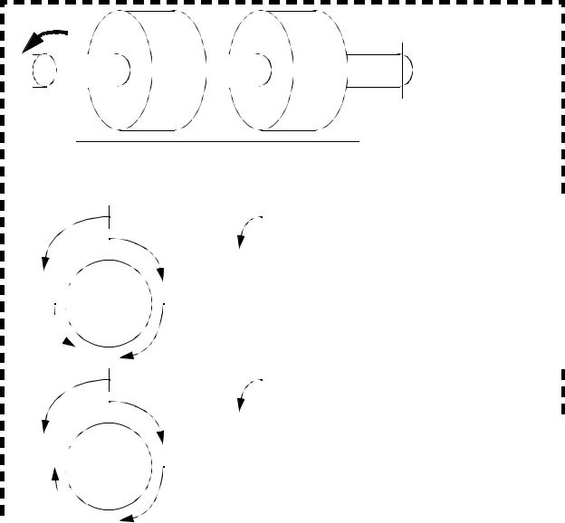
Rotational damping is normally caused by viscous fluids, such as oils, used for lubrication. It opposes angular velocity with the relationships shown in Figure 5.13. The first equation is used for a system with one rotating and one stationary part. The second equation is used for damping between two rotating parts.

T = Kdω

T = Kd( ω 1 ω 2)

Figure 5.13 The rotational damping equation

If a wheel (JM=5kg m2) is turning at 150 rpm and the damping coefficient is 1Nms/rad, what is the deceleration?

ans.

rad

··

θ

=

–3.141--------


s2

Figure 5.14 Drill problem: Find the deceleration

The example in Figure 5.12 is extended to include damping in Figure 5.15. The primary addition from the previous example is the addition of the damping forces to the FBDs. In this case the damping coefficients are indicated with ’B’, but ’Kd’ could have also been used. The state equations were developed in matrix form. Visual comparison of the final matrices in this and the previous example reveal that the damping terms are the

rotation - 5.13

only addition.

τ

JM1

Ks1


B1

Ks2

JM2

Ks3


B2


Model the system above assuming that the center shaft is a torsional spring, and that a torque is applied to the leftmost disk. Leave the results in state variable form.

θ 1

τ

θ 2

Ks3θ 2


θ


1


d

ω

1


----


=


dt


θ

2


ω

2


Ks2( θ 1 θ 2)

JM1

B1θ·1

Ks2( θ 2 θ 1)

JM2


B2θ·2


0


1


0


Ks2

B1


Ks2

-----------


--------

-------


JM1

JM1


JM1

0


0


0


Ks2

0


Ks3 Ks2


-------JM2


--------------------------


JM2


+ M = τ Ks2( θ 1 θ 2) B1θ·1 = JM1 θ··1


JM1 θ··1 = – B1θ·1 Ks2θ 1 + Ks2θ 2 + τ


θ·1

=

ω 1


(1)


·


B1


Ks2


Ks2


τ


ω 1

=

--------


ω

1 +

-----------


θ

1 +

-------


θ

2 +

-------

(2)


J

M1


J

M1


J

M1


J

M1


+ M = – Ks2( θ 2 θ 1) B2θ·2 Ks3θ 2 = JM2 θ··2

··


B2 ·


Ks3

Ks2


Ks2


θ 2 =


--------

θ 2


--------------------------


θ

-------


θ 1


J

M2

+

J

M2


2 + J

M2


θ·2 =

ω


(3)


2


ω

·


B2

ω


=

--------


2


J


M2


0


θ


0


1


0


ω

1


τ


+


-------

1


θ


J

M1


2


0


B2


ω


2


--------


0


JM2


2


Ks3 Ks2

θ 2

+ --------------------------


JM2


Ks2

θ

(4)


-------


+ J

M2


1


Figure 5.15 A System Example

rotation - 5.14

5.2.4 Levers

The lever shown in Figure 5.16 can be used to amplify forces or motion. Although theoretically a lever arm could rotate fully, it typically has a limited range of motion. The amplification is determined by the ratio of arm lengths to the left and right of the center.


F2


d1


d2


F1


δ

2


d1


F2


δ

1


δ 1


----

=

----- =

----


d2


F1


δ

2


Note: As the lever rotates the length ratio will be maintained because of similar triangles. This allows the lever to work over a range of angles. The lever above would become ineffective if it was vertical.

Note: The tip deflection can be related to the angle of

θ


δ 1


δ 2

rotation of the lever if the angle of rotation is small.

=

----

=

----


d1


d2

Figure 5.16 Force transmission with a level

Given a lever set to lift a 1000 kg rock - if the lever is 2m long and the distance from the fulcrum to the rock is 10cm, how much force is required to lift it?

ans.

F = 516.3N

Figure 5.17 Drill problem: Find the required force

rotation - 5.15

5.2.5 Gears and Belts

While levers amplify forces and motions over limited ranges of motion, gears can rotate indefinitely. Some of the basic gear forms are listed below.

Spur - Round gears with teeth parallel to the rotational axis.

Rack - A straight gear (used with a small round gear called a pinion). Helical - The teeth follow a helix around the rotational axis.

Bevel - The gear has a conical shape, allowing forces to be transmitted at angles.

Gear teeth are carefully designed so that they will mesh smoothly as the gears rotate. The forces on gears acts at a tangential distance from the center of rotation called the pitch diameter. The ratio of motions and forces through a pair of gears is proportional to their radii, as shown in Figure 5.18. The number of teeth on a gear is proportional to the diameter. The gear ratio is used to measure the relative rotations of the shafts. For example a gear ratio of 20:1 would mean the input shaft of the gear box would have to rotate 20 times for the output shaft to rotate once.

T1

=

Fc r1

T2 = Fcr2

n1

=

n2


----

----


r1


r2


Vc

=

ω 1r1 =

ω 2r2

r2

=

ω

1

----

--------- =


r1


ω 2

where,

n = number of teeth on respective gears r = radii of respective gears

Fc = force of contact between gear teeth Vc = tangential velocity of gear teeth

T = torques on gears

Figure 5.18 Basic Gear Relationships

T1

=

r1

=

n1


--------

----

----


T2


r2


n2


α 1

=

θ 1

=

n2

--------

------------

----

α 2


∆θ

2


n1

For lower gear ratios a simple gear box with two gears can be constructed. For higher gear ratios more gears can be added. To do this, compound gear sets are required. In a compound gear set two or more gears are connected on a single shaft, as shown in Figure 5.19. In this example the gear ratio on the left is 4:1, and the ratio for the set on the right is 4:1. Together they give a gear ratio of 16:1.

rotation - 5.16


N2 = 60


N2N4


N5 = 15


e = ------------ = 16


N3N5


In this case the output shaft


Input shaft


Output shaft


turns 16 times faster


than the input shaft. If


we reversed directions


Compound gear set


the output (former input)


would now turn 1/16 of


the input (former out-


put) shaft speed.


N3 = 15

N4 = 60

Figure 5.19 A compound gear set

A manual transmission is shown in Figure 5.20. In the transmission the gear ratio is changed by sliding (left-right) some of the gears to change the sequence of gears transmitting the force. Notice that when in reverse an additional compound gear set is added to reverse the direction of rotation.

rotation - 5.17


9

clutch

8

stem gear


2

7

Motor shaft


reverse idler

3

4


10


11


6


5


Speed (gear)


Gear Train


In this manual transmission the gear


shifter will move the gears in and out of


1


2-3-6-9


contact. At this point all of the needed


2


2-3-5-8


gears will be meshed and turning. The


3


2-3-4-7


final step is to engage the last gear in


4


bypass gear train


the gear train with the clutch (plate)


reverse

2-3-6-10-11-9


and this couples the gears to the wheels.


Figure 5.20 A manual transmission

Rack and pinion gear sets are used for converting rotation to translation. A rack is a long straight gear that is driven by a small mating gear called a pinion. The basic relationships are shown in Figure 5.21.

rotation - 5.18

T = Fr

Vc = ω r

l = r∆θ

where,

r = radius of pinion

F = force of contact between gear teeth

Vc = tangential velocity of gear teeth and velocity of rack T = torque on pinion

Figure 5.21 Relationships for a rack and pinion gear set

Belt based systems can be analyzed with methods similar to gears (with the exception of teeth). A belt wound around a drum will act like a rack and pinion gear pair. A belt around two or more pulleys will act like gears.

A gear train has an input gear with 20 teeth, a center gear that has 100 teeth, and an output gear that has 40 teeth. If the input shaft is rotating at 5 rad/sec what is the rotation speed of the output shaft?

What if the center gear is removed?

ans.

case 1: ω

case 2: ω

3

3

=

2.5

rad

--------


s

=

–2.5

rad

--------


s

Figure 5.22 Drill problem: Find the gear speed