

CHAPTER 9
High-Level Language
All the programs we have written in the last six chapters have been in symbolic assembly language. Whilst assembly-level software is a quantum step up from pure machine-level code (see page 198) nevertheless there is still a one-to-one relationship between machine and assemblylevel instructions. This means that the programmer is forced to think in terms of the MCU’s internal structure – that is of registers and memory
– rather than in terms of the problem algorithm. Although most assemblers have a macro facility, whereby several machine-level instructions can be grouped to form pseudo high-level instructions, this is only tinkering with the di culty. What is this di culty with machine-oriented language? In order to improve the e ectiveness, quality and reusability of a program, the coding language should be independent of the underlying processor’s architecture and should have a syntax more oriented to problem-solving.
We are not going to attempt to teach a high-level language in a single short chapter. However, after completing this chapter you will:
•Understand the need for a high-level language.
•Appreciate the advantages of using a high-level language.
•Understand the problems of using a high-level language for embedded microcontroller applications.
•Be able to write a short program in C.
The di culty in coding large programs in a computer’s native language was clearly appreciated within a few years of the introduction of commercial systems. Apart from anything else, computers quickly became obsolete with monotonous regularity, and programs needed to be rewritten for each model introduction. Large applications programs, even at that time, required many thousands of lines of code. Programmers were as rare as hen’s teeth and worth their weight in gold. It was quickly deduced that for computers to be a commercial success, a means had to be found to preserve the investment in scarce programmers’ time. In developing a universal language, independent of the host hardware, the opportunity would be taken to allow the programmer to express the code in a more natural syntax related to problem-solving rather than in terms of memory, registers and flags.


234 The Quintessential PIC Microcontroller
Fig. 9.2 Onion skin view of the steps leading to an executable program.
it is likely to be a team e ort, with all the di culties in integrating the code and foibles of several people. A great deal of self-discipline and skill is demanded of such personnel, as is attention to documentation. Even with all this, the final result cannot be easily transplanted to machines with other processors, needing a nearly complete rewrite.
In the early 1970s, Ken Thompson – an employee at Bell Laboratories
– developed the first version of the UNIX operating system. This was written in assembler language for a DEC PDP7 minicomputer. In an attempt to promote the use of this operating system (OS) within the company, some work was done in rewriting UNIX in a high-level language. The language CPL (Combined Programming Language) had been developed jointly by Cambridge and London universities in the mid-1960s, and has some useful attributes for this area of work. BCPL (Basic CPL) was a somewhat less complex but more e cient variant designed as a compiler-writing tool in the late 1960s. The language B (after the first letter in BCPL) was developed for the task of rewriting UNIX for the DEC PDP11 and was essentially BCPL with a di erent syntax.
Both BCPL and B only used one type of object, the natural size machine word – 16 bits for the PDP-11. This typeless structure led to di culties in dealing with individual bytes and floating-point computation. C (the second letter of BCPL) was developed in 1972 to address this problem, by
9. High-Level Language 235
creating a range of objects of both integer and floating-point types. This enhanced its portability and flexibility. UNIX was reworked in C during the summer of 1973, comprising around 10,000 lines of high-level code and 1000 lines at assembly level. It occupied some 30% more storage than the original version.
Although C has been closely associated with UNIX, over the intervening years it has escaped to appear in compilers running under virtually every known OS, from mainframe CPUs down to single-chip MCUs. Furthermore, although originally a systems programming language, it is now used to write applications programs ranging from Computer Aided Design (CAD) packages down to the intelligence behind smart egg-timers!
For over 10 years the o cial definition was the first edition of The C Programming Language, written by the language’s originators Brian W. Kernighan and Dennis M. Ritchie. It is a tribute to the power and simplicity of the language that over the years it has survived virtually intact, resisting the tendency to split into dialects and new versions. In 1983 the American National Standards Institute (ANSI) established the X3J11 committee to provide a modern and comprehensive definition of C to reflect the enhanced role of this language. The resulting definition, known as Standard or ANSII C, was finally approved during 1990.
Apart from its use as the language of choice for embedded MPU/MCU circuits, C (together with its C++ and Java object-oriented o spring) is without doubt the most popular general-purpose programming language at the time of writing. It has been called by its detractors a high-level assembler. However, this closeness of C to assembly-level code, together with the ability to mix code based on both levels in the one program, is of particular benefit for embedded targets.
The main advantages of the use of high-level language as source code for embedded targets are:
•It is more productive, in the sense that it takes around the same time to write, test and debug a line of code irrespective of language. By definition, a line of high-level code is equivalent to several lines of assembly code.
•Syntax is more oriented to human problem-solving. This improves productivity and accuracy, and makes the code easier to document, debug, maintain and adapt to changing circumstances.
•Programs are easier to port to di erent hardware platforms, although they are rarely 100% portable. Thus they are likely to have a longer productive life, being relatively immune to hardware developments.
•As such code is relatively hardware-independent, the customer base is considerably larger. This gives an economic impetus to produce extensive support libraries of standard functions, such as mathematical and communication modules, which can be reused in many projects.

236 The Quintessential PIC Microcontroller
Of course there are disadvantages as well, specifically when code is being produced to run in poorly resourced MPU/MCU-based circuitry.
•The code produced is less space-e cient and often runs more slowly than native assembly code.
•The compiler is much more expensive than an assembler. A professional product will often cost several thousand pounds/dollars.
•Debugging can be di cult, as the actual code executed by the target processor is the generated assembler code. The processor does not execute high-level code directly. Products that facilitate high-level debugging are, again, very expensive.
Program 9.1 is an example of a C function (a function is C’s counterpart to a subroutine) that evaluates the relationship:
n
sum = k
k=1
for example, if n = 5 then we have:
sum = 5 + 4 + 3 + 2 + 1
In the implementation n is the integer passed to the function, which computes and returns the integer sum as defined. The program implements this task by continually adding n to the pre-cleared sum, as n is decremented to zero.
Let us dissect it line by line. Each line is labelled with its number. This is for clarity in our discussion and is not part of the program.
Line 1: This line names the function (subroutine) summation and declares that it returns an unsigned long integer (a 16-bit unsigned object in the compiler used to illustrate this chapter) and expects an unsigned integer (a 8-bit unsigned object) to be passed to it called n.
Line 2: A left brace { means begin. All begins must be matched by an end, which is designated by a right brace }. It is good practice
Program 9.1 A simple function coded in C.
1:unsigned long summation(unsigned int n)
2:{
3:unsigned long sum = 0;
4:while(n>0)
5:{
6:sum = sum + n;
7:--n;
8:}
9:return sum;
10:}

9. High-Level Language 241
In more complicated expressions the placement of the -- decrement operator (and the analogous ++ operator) before or after the object can a ect the outcome. Where it appears before, such as in:
number = --n + 4;
then the value of n is first decremented before being added to 4. In the following case:
number = n-- + 4;
n is added to 4 and then decremented.
In our example the logic of the program is una ected if the operator is pre-decrement or post-decrement. However, the compiler in the latter case adds an extra instruction to bring n down into the Working register before it is decremented in situ as it thinks that some computation involving the original value of n is to be performed.
}
The while loop is repeated by going back to the loop test, which is located starting at 009h.
goto 009
return sum;
At the end of a function returning a long object the CCS compiler places the two bytes in the fixed GPRs File 0D:Eh ordered low:high. Thus this code fragment simply copies the two bytes in File 12:13h; i.e. sum, into the return locations.
movf |
12,w |
; Copy |
low byte sum |
|
|
||
movwf |
0D |
; and |
put |
in return |
slot |
low |
|
movf |
13,w |
; |
Copy |
high byte sum |
|
|
|
movwf |
0E |
; |
and |
put |
in return |
slot |
high |
|
|
|
|
|
|
|
|
Specifically the main() function is terminated by the sleep instruction – see page 256. Normally a function is terminated by a return to the caller function.
The final machine code file is shown in Table 9.1(b) and gives a total length of only 23 instruction including the one-o environment settings. This is similar to a handcrafted assembly-level equivalent in length and therfore execution time.
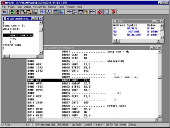
C-level programs can be compiled and simulated in the IDE environment of Microchip’s MPLAB – see page 221. The screen shot of Fig. 9.3 shows windows into both the C-level source code and the resulting assembly-level code. Although simulation is at the latter level the
242 The Quintessential PIC Microcontroller
Fig. 9.3 Simulating our example program in MPLAB.
C code is highlighted in the appropriate place corresponding to the simulated assembly-level instruction. The Watch window shows the state of the two C objects int n (corresponding to the assembly label MAIN.N) and long sum (i.e. MAIN.SUM). The compiler generates the system symbol _RETURN_ to label the two GPRs File 0D:0Eh and this can be monitored in the normal way.
Using C to implement source code gives the programmer access to structures, operators and libraries appropriate to a modern high-level language. Nevertheless, any coding language of use in an embedded MPU/MCU target must be able to address locations in Data memory and specific bits in a datum. This enables the programmer to get into a SPR and monitor and change flags. In Part 3 of this book we will use both assembly and C codings to interact with internal and external hardware. However, it will be useful to introduce the use of C in a ‘bit banging’ role here.
Consider a program fragment that has to check the state of the Timer 0 (TMR0) SPR at File 01h and if it is decimal 24 zero it. This is how it might be done in C.


9. High-Level Language 245
Examples
Example 9.1
Write a C function to return the square root of a positive 16-bit integer. The algorithm of Fig. 6.9 on page 162 is to be used to implement the conversion.
Solution
Modifying the task list of Example 6.5 to suit the structure of the C while loop gives:
1.Zero the loop count
2.Set variable i (the magic number) to 1
3.WHILE i is less than or equal to the number
(a)Take i from Number
(b)Add 2 to i
(c)Increment the loop√ count
4. Return loop count as Number
The function heading gives it its name sqr_root and defines the parameters to be passed to the function and the outcome. The form unsigned int sqr_root(unsigned long number) declares that it will return an unsigned int value and one unsigned long int object will be passed to it, which will be known as number within the function. On this basis the coding of Program 9.2 directly implements the task list. As the square root of a 16-bit object will fit into an 8-bit byte, the loop count is declared unsigned int. The magic number i will however be twice (plus one) that of count and is therefore defined as a unsigned long object. At the same time as these internal function variables are defined they are given their initial values.
The while loop is repeated until the value of the reducing number drops below the increasing value of i, at which point any further subtraction will drop the outcome below zero. The value of the loop count is the square root and is returned to the caller at the end of the function.
Program 9.2 Coding the square root function.
unsigned int sqr_root(unsigned long number)
{
unsigned int count = 0; unsigned long i = 1; while(number>=i)
{
number = number - i; i = i + 2;
count++;
}
return count;
}

9. High-Level Language 247
As we are told that only the 14 lower bits of emf have any meaning, line 4 ANDs the 16-bit object with 3FFFh (0x3FFF) to clear the upper two bits. The 0x prefix is C’s way of denoting hexadecimal.
Finally an unsigned long version of the float object temperature is made and returned in line 8.
The resulting executable code running on a mid-range PIC core takes 667 program words; or around 23 of the Program store of a PIC16F84 device. Because of the size penalty of using floating-point objects, fixedpoint arithmetic is used wherever possible in embedded microcontroller implementations.
Example 9.4
On page 213 we implemented a root mean square program to implement
the mathematical relationship NUM_12 + NUM_22. Write a C function to implement this relationship, where the two 8-bit objects num_1, num_2 are passed to the function which returns the 8-bit value rms.
Solution
The solution shown in Program 9.4 uses the internal unsigned long 16-bit variable sum to hold the addition of the two squared 8-bit variables. The squaring operation is simply implemented using the C multiplication operator * rather than coding a squaring function of the manner of Program 8.3 on page 215. The function developed in Program 9.2 is used to
Program 9.4 Generating the root-mean square value of two variables.
unsigned int variance(unsigned int num_1, unsigned int num_2)
{
unsigned long sum; unsigned int rms;
sum = (unsigned long)num_1*num_1 + (unsigned long)num_2*num_2; rms = sqr(sum);
return rms;
}
unsigned int sqr(unsigned long number)
{
unsigned int count = 0; unsigned long i = 1; while(number>=i)
{
number = number - i; i = i + 2;
count++;
}
return count;
}
248 The Quintessential PIC Microcontroller
generate the square root of the 16-bit sum object and is called from the function variance() line 6 with the return value being assigned to the variable sum as part of the call. In compiling the source code using the CCS C compiler, 100 machine-level instructions are needed to implement this problem. This compares to 62 instruction for the assembly-code version of Chapter 8. This gives an e ciency ratio of 62%.
Self-assessment questions
9.1The coding of Program 9.2 can be simplified if it is observed that the variable i is always twice count plus one, so count is not needed. Instead, on return the 16-bit value i can be logic shifted once right (see page 11) and the 8-bit cast version of the remainder is the equivalent of the absent count. In shifting right the datum is divided by two and by throwing away the one that pops out, e ectively subtracts by one (i is always odd and so its least significant bit is always 1). Try coding this alternative arrangement. The C operator to shift right by n places is >> n. If the datum is unsigned then the shift is a logic shift right. See Example 9.3 to see how to cast a datum to another type.
9.2A PIC-based digital thermometer is to display temperatures between 0◦C and 100◦C. To be able to market the device to USA the thermometer is to have the option to display the temperature in Fahrenheit. Write a function for a PIC-based thermometer that is to convert Celsius integers to the equivalent Fahrenheit integer. The input is to be an unsigned int byte representing Celsius and the return Fahrenheit is also to be an unsigned int datum. The relationship is:
fahrenheit = (celsius × 9)/5 + 32
and the arithmetic should be done in 16-bit precision to avoid overrange.
9.3 A cold-weather indicator in an automobile dashboard display comprises three LEDs, which are connected to the lower three bits of Port A. Bit 2 of this location is connected to the red LED, which is to light if the Fahrenheit temperature is less than 30. Bit 1 is the yellow LED for temperatures below 40◦F, and bit 0 is the green LED. Write a function, whose input is ◦F, that activates the appropriate LED.
Access to the LEDs through Port A at File 05h in C can be accomplished by placing the following line of code at the head of the program: You may assume that a logic 0 at the appropriate Port A pin

9. High-Level Language 249
lights the LED. You may also presume that the three appropriate Port A bits have been set to output mode.
#define LED *(unsigned int *)0x05
whereupon the variable LED can be altered like any other variable. You will also need to use the if-else conditional construction:
if(something is true) {do this;}
else if(whatever is true) {do that;}
else
{do the other;}
9.4 Arrays of objects can be defined in C using the notation fred[n] where fred is the name of the array and n is the nth element. For example an array of ten values making up the decimal 7-segment patterns described in Fig. 6.6 on page 148 can be defined and initialized as:
unsigned int 7_seg[10] = {0xc0, 0xf9, 0xa4, 0xb0, 0x99, 0x92, 0x82, 0xf8, 0x80, 0x90};
These ten values for 7_seg[0] through 7_seg[9] will be placed in ten sequential file registers. As most PICs have a severally limited number of GPRs and this example is a array of constants it makes more sense to place these ten constant bytes in Program ROM. Using the key word const in front of the array definition tells the compiler to initialize Program store locations instead.
unsigned int const 7_seg[10] = {0xc0, 0xf9, 0xa4, 0xb0, 0x99, 0x92, 0x82, 0xf8, 0x80, 0x90};
As data in the Program store is not directly accessible in the lowand mid-range PIC Harvard architecture the compiler will actually place a series of retlw <byte> instructions in ROM as described in Table 6.4 on page 149.
Based on the above array definition, code a C functionto return the 7-segment code equivalent of an unsigned int n passed to the function.
9.5 As part of a digital game a PIC is to drive an active-low 7-LED display to implement an electronic die. Our problem, outlined in Fig. 9.4, is to convert a ’throw’ number n between 1 and 6 to the 7-bit display.

250 The Quintessential PIC Microcontroller
Code a C function converting n, which is passed to the function, and returning the appropriate code pattern.
|
|
|
Throw pattern[n] a |
b |
||
|
|
|
n |
gfedcba |
f |
g c |
|
|
|
e |
d |
||
|
|
|
1 |
0111111 |
|
3Fh |
Throw |
Function |
Die pattern |
2 |
1110110 |
|
76h |
3 |
0110110 |
|
36h |
|||
n |
die() |
pattern[n] |
|
|||
|
|
|
4 |
1100100 |
|
64h |
|
|
|
5 |
0100100 |
|
24h |
|
|
|
6 |
1000000 |
|
40h |
Fig. 9.4 The active-low die patterns.
9.6Driving the die requires seven parallel port lines and the electronic game requires to drive two die displays. By inspection of the patterns of Fig. 9.4 how could you reduce the requirement to four bits only?
9.7As part of the same electronic game a function is to be written to return the next pseudo random number in the 127 sequence defined by the generator configuration of Fig. 3.12 on page 70. The current number is to be passed to the function and the next number in the sequence returned. It may be assumed that this passed datum is never zero.
How could you modify the function to send the sequence of all 127 pseudo random numbers out of Port B beginning with the passed number?
9.8To integrate the outcome to the pseudo random function with the die display we need to map the set of 127 numbers to the range one to six. Devise a modified function to implement the mapping. Hint: What simple mathematical operation would map any number to the range zero to five?