

CHAPTER 7
Interrupt Handling
The subroutines discussed in Chapter 6 are predictable events in that they are called up whenever the program dictates. Real-time situations, defined as where the processor interacts in concert with external physical events, are not as simple as this. Very often something happens beyond the CPU which necessitates precipitate action from the processor. The vast majority of MPU/MCUs have the capability to deal with a range of such events that disrupt their smooth running. In the case of a microcontroller, requests for service may come from an internal peripheral device, such as a timer overflowing, or the completion of an analog to digital conversion, or from a source entirely external to the device in the outside world. At the very least, on reset (a type of external hardware event) the MCU must be able to get (vector) to the first instruction of the main program. In the same manner an external service request or interrupt when answered must lead to the start of the special subroutine known as an interrupt service routine.
In this chapter we will be examining how the PIC16F84 handles interrupts originating both internally and externally. The other mid-range PICs handle interrupts in a similar manner, but have a di erent mix of internal peripheral devices, such as an analog to digital converter, which will be discussed in Part 3 of the text.
After reading this chapter you will:
•Appreciate the need for interrupt handling.
•Appreciate the concept of a vector table as a jumping-o point for reset and interrupt events.
•Follow the sequence of events when the PIC recognizes an interrupt request.
•Understand the principle of latency.
•Have an understanding of the concept of the global interrupt mask.
•Understand the operation of the local interrupt mask and flag pairs and how this is implemented in the INTCON and EECON1 file registers corresponding to the various source of interrupts.
•Be able to write a simple interrupt handler involving the following principles:
–Context switching.
–Determination of interrupt source.
–Return via the retfie instruction.

172 The Quintessential PIC Microcontroller
A simple example of a time-sensitive requirement is shown in Fig. 7.1. Here we wish to measure the elapsed time between R points of an electrocardiogram (ECG) signal; by definition an external real-time event. The time resolution is to be 0.1 ms and the maximum peak-peak duration is likely to be no more than 1.5 seconds. In order to measure this time a freerunning 16-bit counter clocked at 10 kHz can be used as the time base. As we shall see in Chapter 13, the mid-range PICs have an internal 8-bit counter at File 01 and Fig. 7.1 shows File 3Fh used as an extension byte to give a total 16-bit count. The details of this configuration are discussed in Program 13.2 on page 370. Here we will assume that the state of the count can be read at any time from these two specified file registers. If the count at the last R point is stored in two spare file registers, then subtraction of the count at the current R point will give the required beat-to-beat duration.
Event Subsystem
t
R R
Peak Detector
Please respond quickly
|
|
|
|
|
|
16-bit Counter |
|
|
|
|
|
|
|
||
10 kHz |
File 3Fh |
File 01 |
|||||
|
|
||||||
Oscillator |
|
|
|
|
|
|
|
MCU
Fig. 7.1 Detecting and measuring an external event.
The next problem is how to detect the signal peak, as by definition the patient’s ECG signal is not synchronized to the MCU! One technique is to continually read this signal and perform a peak-detection algorithm to determine the R point. Now this polling technique will have to be carried out 10,000 times each second in order to keep to the specified resolution and taking a nominal human heartrate of 60 beats per minute, 99.99% of the time no peak will be detected. Essentially, this means that the processor will spend the vast majority of its processing power just looking out for one event in 10,000.

7. Interrupt Handling 173
The alternative approach is to use external hardware who’s task is to find the peak signal. That peak-picking hardware could be an analog circuit or even a MCU with an analog to digital converter dedicated to this one task – see Example 14.4 on page 424. Whatever the implementation, the peak-picker sends a signal to the main processor when a R point has been detected. This signal interrupts the MCU which must drop whatever it is doing and read the counter within 100 µs if a counter tick is not to be missed.
In the situation where external processes happen in their own good time and are in no way synchronized to the processor, there has to be some way for certain events to interrupt the process and direct it to attend to their immediate need. Polling a series of outside events is adequate where nothing much happens quickly outside and/or there are few parameters to monitor and little processing to do. The possibility of missing anything important can be reduced by increasing the polling rate, but there comes a time when the MPU does little else but read peripheral data. This resource burnout is especially a problem when there are many signals to poll in a short period of time.
The downside of interrupt-driven real-time monitoring is additional hardware complexity and the greater intricacy of the hardware–software interface. If you are confused, consider the telephone system. It would be possible to have a telephone network where the subscriber would pick up the phone every, say, 5 minutes and ask “Is there anyone there?”. Apart from the bother (processing overhead) of doing this,1 the caller may have got bored and hung up. You could reduce the chance of this happening by increasing the polling rate to, say, once per minute. But you could then end up spending all your time on the phone and, depending on how popular you are, getting only a few hits a day. That is, 99% of your e ort is wasted.
This is obviously ridiculous, and in practice an interrupt-driven technique is used so that you only respond when the bell/buzzer sounds. Highly e cient, but at the cost of a lot more complexity for the phone company, as the signalling side of the system can be more demanding than the speech side. There is another problem too, in that you (cf. the processor) have no idea when the phone will ring. And it surely will be at the most inconvenient time. Thus you have to (unless you have an iron will) break o what you are doing at the drop of a hat. For example, if you happen to be in the middle of solving a problem in your head you should save your partial results before responding, so, when finished, you can return to where you left o .
Keeping this apparent randomness (at least as seen by the MCU) in mind the following phases can usually be identified, although the minu-
1It would of course make it easier just to ignore the phone…!

174 The Quintessential PIC Microcontroller
tiae of the response to an interrupt request varies considerably from processor to processor.
1.Finishing the current instruction.
2.Automatically saving, at the very least, the state of the Program Counter (PC), which is needed to get back. Some processors also automatically save the Status register and other internal registers at this point.
3.Entering the appropriate interrupt service routine.
4.Executing the defined task.
5.Restoring the processor state and returning to the point in the background program where control was first transferred.
Essentially signalling an interrupt causes the PIC to drop whatever it is doing, save its position in the interrupted background program and go to a special subroutine known as an Interrupt Service Routine (ISR). This foreground program is just a subroutine entered at the behest of an external happening.
The midand upper-range PIC core can be interrupted by a range of events. For example, the PIC16F84 will respond to service requests from four sources.
1. An external signal at pin 6 (see Fig. 4.2 on page 85) which is labelled INT in this context, but doubles as the Port B bit 0 RB0 pin. The request may be activated optionally by either a rising edge / or a falling edge \ at this input.
2.An input change at any of the top four Port B (File 6) pins since the last read of this port.
3.By the Timer counter TMR0 (File 1) overflowing FF → 00h.
4.When an internal Data EEPROM write-to action has been completed.
We will look at how each of these can request an interrupt service later in the chapter. However, the PIC’s response to an interrupt is functionally identical from whatever source it comes from; so for the moment for simplicity we will assume that some event (maybe the peak-picker in Fig. 7.1) wants service and has pulsed the INT pin.
The PIC’s response to such an event is shown in a simplified manner in Fig. 7.2. Essentially the sequence is:
1.The processor samples the interrupt line once in each instruction cycle. If this line is active a latch is set, otherwise it is cleared. This latch is called the interrupt flag. Irrespective of the state of this line, the current instruction is always completed; that is execution does not break part way through the instruction, even in a 2-cycle instruction.
2.If the interrupt flag is not active, the PIC simply continues on into the next instruction cycle and the process is repeated.
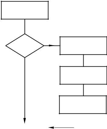
Finish current instruction
Interrupt line active?
 No
No
Next instruction
7. Interrupt Handling 175
Yes
Clear GIE
Stack PC
Goto 004h
Interrupt service routine
retfie
Fig. 7.2 Responding to an interrupt request.
3.If both the interrupt flag is set and bit 7 of the INTCON special purpose register (see Fig 7.4) is clear, the next three instruction cycles are involved in moving execution to the interrupt service routine, although the first of these may be the final cycle of a 2-cycle instruction otherwise a dummy cycle, plus two more cycles to flush the pipeline. This 3 to 4-cycle delay from the instant of the hardware INT signal and beginning the execution of the first instruction of the ISR is known as latency. It is impossible to be more precise due to the time-random nature of the external request signal which can occur anywhere in the instruction cycle.
4.During this latency period the PIC does three things:
(a)Bit 7 of the INTerrupt CONtrol register (INTCON at File 0Bh) is zeroed. This bit is labelled in Fig. 7.4 as General Interrupt Enable (GIE). Once GIE is cleared all further requests for interrupts from whatever source are locked out, so an interrupt service process cannot be further interrupted. GIE is an example of an Interrupt mask as it is able to mask out interrupt activity. After reset GIE is cleared, so by default interrupt activity is disabled.

176The Quintessential PIC Microcontroller
(b)The state of the 13-bit Program Counter is pushed into the hardware stack in exactly the same manner as for a call instruction
– see Fig. 6.3 on page 141. As for subroutines, this is to allow the processor to return to the interrupted background program after the interrupt service routine. As the mid-range PICs have an 8-deep hardware stack, subroutines nested to depth of seven can be called from an ISR.
(c)The first instruction of the ISR is always in location 004h in the Program store. Thus the final step of the sequence is to overwrite the PC with this instruction address, known as the Interrupt vector. If the interrupt handling software is elsewhere in Program memory then this entry instruction can of course be a goto instruction; see Program 7.1.
5.Like a subroutine, an ISR must be terminated by a Return instruction. However, in this case not only has the PC to be pulled out of the hardware stack to move execution back to the interrupted program but the GIE bit in the INTCON register must be set to re-enable the interrupt capability. This counteracts the resetting of this bit in 4(a) above on entry to the ISR. The Return instruction relevant to this situation is retfie (RETurn From Interrupt and Enable). Thus on reentry to the background program any pending or future interrupts can be serviced.
An ISR di ers from a subroutine in more subtle ways than the use of the retfie instruction of item 5 above. Some of these di erences relate to the logic of the interrupt system and some are due to the pseudo random nature of the interrupts. Discussing the former first, let us examine the logic circuitry relating to the interrupt process.
Interrupt flag |
|
|
|
To PIC control circuitry |
|
|
|||
Interrupt mask |
|
|
|
|
|
|
|
||
|
|
|
|
|
|
|
|
Fig. 7.3 The flag:mask pair.
Each of the four PIC16F84 interrupt sources interact with the processor via two associated control register bits, as shown in Fig. 7.3. The flag bit is set when the related source device requests service. For example, if the Timer 0 overflows FFh → 00h then bit 2 of the INTCON register, labelled T0IF (Timer 0 Interrupt Flag) is set to 1. If the local mask bit is 1 (bit 5 of INTCON labelled T0IE for Timer 0 Interrupt Enable) then the request will go forward to the next layer of interrupt logic. Note that the state of the mask bit does not a ect the setting of the associated interrupt flag. Thus if the mask bit is zero, a polling technique can still be
7. Interrupt Handling 177
used to determine if an event has occurred by checking the state of the appropriate interrupt flag.
The local mask bit can be written to in the normal way by software. On reset it is zeroed and thus the interrupt from the a liated source disabled. To set it to one, use the bsf instruction. For example, bsf INTCON,5 to set the T0IE mask. The interrupt flag can also be written to by software, as well as being externally set by the requesting device. The ISR must clear it, eg. bcf INTCON,1, before return to cancel the request otherwise an endless series of interrupts will occur. This is because on return the interrupt flag will still be set and another interrupt will immediately be set in train.
As there are four sources of interrupt, each flag:mask AND gate must be ORed to give a composite request signal, which when active initiates the CPU’s interrupt response. In Fig. 7.4 this ORing process is further gated with the Global mask bit GIE, which is located in bit 7 of INTCON. However, the raw, i.e. pre-globally masked, request signal is used to awaken the processor if it is in a power-down or sleep state. As we will see in Chapter 10 the current consumption of the device can be considerably reduced to typically 1 µA if processing is stopped and the PIC is put in a state of suspended animation. For example, monitoring the temperature profile at the bottom of a lake over a period of a year at one hour intervals using a battery-powered data logger requires processing for a tiny proportion of the time. Placing the PIC in this power-down mode after each sample has been taken and stored will reduce the necessary battery capacity. The sleep instruction initiates this mode. An interrupt from an outside source, in this case a low-power hourly oscillator, is used to wake the PIC up. As shown, this awakening is independent of the setting of the General mask.
The Timer 0, External and Port B Interrupt flags are located in the INTCON register at bits 2, 1, 0 respectively. These peripherals are common across all mid-range PICs and appear in the same location for these devices. That for the internal Data EEPROM is separately located in the EECON1 Special Purpose Register (SPR) in Bit 4 – see Fig. 15.2 on page 434. Bit EEIF is set whenever a write-data action has been completed.
The Data EEPROM is peculiar to the PIC16F83/4 devices. Other PICs substitute alternative flags for their specialized peripheral devices. For example, the PIC16C71 uses bit 1 of its ADCON0 (A/D CONtrol 0) as the ADIF flag to show that the internal A/D converter has finished its conversion. More sophisticated PICs have more than one interrupting device beyond the three standard ones – INT, Timer 0 and Port B. For instance, the PIC16C74 has eight (plus the standard three) interrupt sources, including two additional timers, a multichannel A/D converter and two serial ports. In this case each such peripheral has its own interrupt flag

178 The Quintessential PIC Microcontroller
|
|
INTerrupt |
CONtrol |
||
7 |
6 |
5 |
4 |
3 |
2 |
GIE |
EEIE |
T0IE |
INTE |
RBIE |
T0IF |
(R/W 0) |
(R/W 0) |
(R/W 0) |
(R/W 0) |
(R/W 0) |
(R/W 0) |
|
|
|
|
|
|
|
|
|
|
|
|
|
|
|
|
|
|
|
|
|
|
|
|
|
|
|
|
|
|
|
0)(R/W |
4 EEIF |
|
|
|
|
|
|
|
|
3 overflow Timer0 |
|||
|
|
|
|
|
|
|
|
|
||||||
|
|
|
|
|
4 write EEPROM |
|
||||||||
|
|
|
|
|
|
|
|
|
||||||
|
88h File |
EECON1 |
|
|
|
|
|
|
||||||
|
|
|
|
|
|
|||||||||
|
|
|
|
|
|
|||||||||
|
|
|
|
|
|
|
|
|
|
|
|
|
|
|
|
|
|
|
|
|
|
|
|
|
|
|
|
|
|
|
|
|
|
|
|
|
|
|
|
|
|
|
|
|
|
|
|
|
|
|
|
|
|
|
|
|
|
|
|
|
|
|
|
|
|
|
|
|
|
|
|
|
|
|
|
|
|
|
|
|
|
|
|
|
|
|
|
|
|
S |
1 |
INTF
(R/W 0)
2 interrupt Hardware
INT
|
|
0 |
|
|
|
|
|
|
|
RBIF |
|
INTCON |
|
||||||
|
|
||||||||
(R/W ?) |
|
File 0Bh/8Bh |
|
||||||
|
|
|
|
|
|
|
|
|
|
|
|
|
|
|
|
|
|
|
|
|
|
|
|
|
|
|
|
|
|
changePORTB |
|
|
|
|
|
1) (R/W |
6 INTEDG |
|
|
|
|
|
|
|
|
||||
|
|
|
|
|
81h File |
OPTION |
|
||
|
|
|
|
|
|||||
1 |
|
|
|
|
|
|
REG |
|
|
|
|
|
|
|
|
|
|||
CPU to Interrupt |
mode) sleep in (if up Wake |
Fig. 7.4 The PIC 16F84’s interrupt logic.
together in a Peripheral Interrupt Register, as shown in Fig. 14.10(b) on page 408.
The INTCON register also holds the four local mask bits corresponding to the PIC16F84’s standard peripherals, besides the Global mask. The programmer can selectively disable or re-enable one or more interrupting source as desired. Thus if it is undesirable for Timer 0 to interrupt a section of code dealing with, say, multiple-precision arithmetic (see Ex-
7. Interrupt Handling 179
ample 7.2) then T0IE can be cleared for the duration of that routine. Other PIC devices replace the EEIE mask by one appropriate to their additional peripheral. Thus the PIC16C71 has ADIE (Analog to Digital Interrupt Enable) as bit 6 of INTCON. PICs with more than one additional peripheral use this bit to enable all these extra requests as a single group, called PEIE (PEripheral Interrupt Enable). However, all these extra devices have their own local masks together in a Peripheral Interrupt Enable register, giving three layers of mask – see Fig. 14.10(b) on page 408.
As there is only one common interrupt vector, i.e. at 004h, then one of the first tasks the ISR has to do is check which peripheral is calling for help. All interrupt flags can be read, so these can be polled in turn until the one that is set is found. Based on this approach a typical polling sequence could be:
STATUS |
equ 03 |
|
; The Status register |
||
INTCON |
equ 0Bh |
; The INTerrupt CONtrol register |
|||
RP0 |
equ 5 |
|
; bit 5 of which is the RP0 bit |
||
EECON1 |
equ 88h |
; The EEPROM CONtrol 1 register |
|||
|
bsf |
STATUS,RP0 |
; |
Change to Bank 1 registers |
|
|
btfsc |
INTCON,1 |
; |
Check for external interrupt |
|
|
goto |
EXTERNAL |
; |
IF set THEN go to INT handler |
|
|
btfsc |
INTCON,2 |
; |
Check for Timer0 interrupt |
|
|
goto |
TIMER0 |
; |
IF set, go to TMR0 handler |
|
|
btfsc |
INTCON,0 |
; |
Check for change at PortB int |
|
|
goto |
CHANGE_B |
; |
IF set, go to correct handler |
|
|
btfsc |
EECON1,4 |
; |
Check EEPROM write-to inter |
|
|
goto |
EEPROM_WR |
; |
IF set, go to EEPROM handler |
|
IRQ_EXIT |
bcf |
STATUS,RP0 ; |
Return to Bank 0 registers |
||
|
retfie |
|
|
; |
and return |
|
|
|
|
|
|
The order of polling gives a priority level if more than one interrupt request should coincide. Thus if both the external hardware and Timer 0 interrupts are active, the former will be processed first. In this case, on return the pending Timer 0 interrupt requests will then be processed
– unless another higher-priority interrupt request has occurred. In all instances the appropriate interrupt flag should be cleared, otherwise the interrupt will be generated indefinitely!
Where masks are set, this same polling technique can be used to check on the status of events without using the PIC’s interrupt processes. For example, when a byte is written to the Data EEPROM (see Program 15.2 on page 436) the program typically checks the state of EEIF (bit 4 of EECON1) until it is set, then clears it and continues on.

180 The Quintessential PIC Microcontroller
W_LOOP btfss |
EECON1,EEIF |
; |
Check state of the |
EEIF flag |
goto |
W_LOOP |
; |
IF still zero THEN |
try again |
; ELSE continue after clearing the write-to EEPROM flag bcf EECON1,EEIF
Figure 7.4 shows additional logic particular to the external INT pin. INTF is set on a falling edge. By interposing an XOR gate as a programmable inverter, as described on page 14, the active edge on the INT pin can be controlled from bit 6 of the Option register – see also Fig. 13.2 page 363. If INTEDG is 0 then INTF will be set on a falling edge at INT whilst a rising edge is active when INTEDGE is 1, which is the default on reset.
Interrupts happen randomly as viewed by the software and thus, unless masked out, may happen at any part of the background software, including in the middle of a subroutine. An ISR foreground routine uses the internal processor registers in the same way as any other software, so conflict over such resources will exist. For example, the background program could just be testing an object when an interrupt occurs. The Skip instruction which follows the test could be dependent on, say, the state of the Zero flag in the Status register. However, the ISR will in all probability alter Z and thus on return the background program will execute the skip, oblivious of the fact that execution has been transferred in the interregnum. Any change to Z would cause an erroneous branch in the background program. Trying to debug this sort of problem is virtually impossible because the e ect of such an interrupt is sporadic as the particular bug depends on the interrupt occurring at just this wrong time and wrong place – something it may do perhaps once a week – and thus is di cult to reproduce.
Another example is illustrated in the polling listing on page 179. Here on entry to the ISR, bit RP0 of the STATUS register (see Fig. 4.6 on page 92) was set to allow access to Bank 1 SPRs. This was necessary as the EEPROM control registers only appear in this bank, whilst both the STATUS and INTCON SPRs are shadowed in both banks. At the exit point, RP0 is cleared to move back to Bank 0. However, this assumes that the background program was in Bank 0 when interrupted. Clearly this is erroneous if an interrupt occurs during an access to Bank 1.
All but the most elementary ISR will need to, at the very least, save the STATUS and Working registers. Generally the programmer sets aside two File registers as temporary storage and for no other use. Traditionally such locations are named with a leading underscore to show that they are used for system purposes and are not to be tampered with by the User’s program. In Program 7.1 File 1Ch and File 1Dh are labelled _work and _status to conform to this convention.

7. Interrupt Handling 181
Program 7.1 Background program for the pea canning packer.
STATUS |
equ |
03 |
; The STATUS register |
Z |
equ |
2 |
; and bit2 is the Zero flag |
RP0 |
equ |
5 |
; and bit5 is the Register Page bit |
PORTA |
equ |
05 |
; Port A |
TRISA |
equ |
85h |
; whose direction register is in Bank1 |
INTCON |
equ |
0Bh |
; INTerrupt CONtrol register |
INTF |
equ |
1 |
; in which bit1 is the INTerrupt Flag |
INTE |
equ |
4 |
; and the associated mask is bit4 |
GIE |
equ |
7 |
; and the global mask is bit7 |
_work |
equ |
1Ch |
; Place for the background Working register |
_status |
equ |
1Dh |
; and the background STATUS register |
EVENT |
equ |
20h |
; Keeps count of cans of peas |
; **************************************************************
|
org |
0 |
; |
Resets here |
|
MAIN |
goto BACKGND |
; |
Go to start |
of background routine |
|
; **************************************************************
org |
04 |
; |
The interrupt vector |
goto |
CAN_COUNT |
; |
Go to start of foreground ISR |
;**************************************************************
;Background program starts by setting up and initialization
BACKGND |
bsf |
STATUS,RP0 |
; |
Change to Bank1 |
|
bcf |
TRISA,0 |
; |
Make bit RA0 an o/p by clearing TRIS0 |
|
bcf |
STATUS,RP0 |
; |
Go back to Bank0 |
|
movlw |
d’23’ |
; |
Very first value is a dummy dec 23 |
|
movwf |
EVENT |
|
|
|
clrf |
INTCON |
; |
Zero any set interrupt flags |
|
bsf |
INTCON,GIE ; |
Enable all interrupts |
|
|
bsf |
INTCON,INTE; |
Enable external INT-pin interrupts |
|
; WHILE event count is less than one DO nothing |
||||
LOOP |
movf |
EVENT,w |
; |
Get event count |
|
sublw |
1 |
; |
Compare with one |
|
btfss |
STATUS,Z |
; |
Is it equal? |
|
goto |
LOOP |
; |
IF not THEN try again ELSE skip |
; Now wait until count is back to zero |
||||
M_LOOP |
movf |
EVENT,f |
; |
Test for zero |
|
btfss |
STATUS,Z |
; |
Skip IF Zero |
goto M_LOOP
; Pulse on the 24th can bsf PORTA,0
call DELAY bcf POTRA,0
goto LOOP
;ELSE try again
;Bring line RA0 high
;Wait for one millisecond
;and go low again
;DO forever
; **************************************************************
; * Subroutine delays for a nominal millisecond at 4MHz * ; **************************************************************
DELAY |
movlw |
0FFh |
; Count down from 255d: |
1˜ |
|
|
|
|
D_LOOP |
addlw |
-1 |
; Decrement |
: |
(255 |
x 1)˜ |
||
|
btfss |
STATUS,Z |
; Until zero |
: |
(255 |
X |
1) + 1˜ |
|
|
goto |
D_LOOP |
; |
: |
(255 |
X |
2)˜ |
|
|
return |
|
; |
: |
2˜ |
|
|
|
|
|
|
|
|
|
|
|
|

182 The Quintessential PIC Microcontroller
Taking as a simple example, consider a conveyer belt in a pea-canning factory. As part of the automatic packing system, a photocell generates a single short pulse for each passing can. The packing machine requires a nominal 1 ms high-going pulse / \ after each batch of 24 cans passes the photocell. Using a PIC16F84 with the photocell sensor connected to the INT pin and the Port A’s pin 0 (RA0) driving the packing machine, design both the background and foreground software. Assume that the PIC is being clocked using a 4 MHz crystal.
A suitable background routine is shown in Program 7.1. There are three distinct phases in the code.
Initialization
This phase begins just after the Interrupt vector at 004h. The PIC always resets to the first instruction in the Program store, i.e. 00h, the Reset vector. The first instruction is simply goto BACKGND where BACKGND is the instruction at 005h. Notice how the org directive is used to place this label at 005h.
As interrupts are automatically disabled on reset, the various File registers and ports are normally set to their initial value at the beginning of the background program before interrupts are enabled. This eliminates the possibility of servicing an interrupt before the initialization code has been completed. The initialization schedule is:
1. All parallel port lines are configured as inputs on reset. To change Port A bit 0 to an output, the associated bit in the TRISA SPR must be cleared. As TRISA is located in Bank 1, RP0 in STATUS is used to switch banks – see page 93. More details are given in Chapter 11.
2.The file register used by the ISR to hold the photocell pulse count is set to an initial value of 23. When the first can passes the sensor, the ISR will set this back to zero thinking that 24 cans have now passed.
3.Clearing all bits in the INTCON register clears all interrupt flags that may have been set since reset. This is important as such flags may be set irrespective of the state of the associated mask bits. Setting the Global Interrupt Enable mask bit now enables the interrupt system and specifically setting INTE enables interrupts from the INT pin.
Main routine
The core of the background software repetitively checks the state of the EVENT file register, which is incremented behind the scenes in the ISR. Initially it waits until EVENT passes a count of one. It then checks for a subsequent zero, which occurs when the ISR detects the first can following event 23. That is the count rolling over 22 → 23 → 0. When a zero is detected RA0 is set high, a 1 ms delay subroutine is called, and then RA0 is brought low again.
The sequence is then repeated indefinitely. The initial wait until EVENT is one ensures a ratchet action, with only one outcome / \ for each zero count in EVENT.

7. Interrupt Handling 183
Delay subroutine
The delay subroutine immediately follows the endless loop main routine. The hold o is implemented by decrementing from FFh to zero, with W holding the count. This takes 1026 cycles including the launching call, which at 1 µs per cycle is nominally 1 ms.2
Program 7.2 Event counting foreground software.
CAN_COUNT |
|
|
|
|
|
|
movwf |
_work |
; Save current |
W reg. in Data |
memory |
||
swapf |
STATUS,w |
; |
Get |
current Status, don’t change flags |
||
movf |
_status |
; |
and |
put away |
in Data memory |
|
; *************************************************************
bcf |
INTCON,INTF |
; Clear the hardware interrupt flag |
incf |
EVENT,f |
; Record one more event |
movf |
EVENT,w |
; Get count |
sublw |
d’23’ |
; Compare with 23 (23 - EVENT) |
btfss |
STATUS,NB |
; IF lower or same THEN skip to finished |
clrf |
EVENT |
; ELSE zero can count |
; *************************************************************
swapf |
_status,w |
; Untwist |
& get original Status from mem |
||
movwf |
STATUS |
|
|
|
|
swapf |
_work,f |
; Now |
get |
original Working register from |
|
swapf |
_work,w |
; |
Data memory without altering flags |
||
retfie |
|
; |
and |
return to interrupted background |
|
|
|
|
|
|
|
When an interrupt occurs the PIC always executes the instruction located at 004h, the Interrupt vector. We see from phase 1 of the background program that this causes execution to transfer to the instruction labelled CAN_COUNT, the first instruction in Program 7.2; that is
Interrupt 004h → CAN_COUNT.
The foreground program, or interrupt service routine, can also be divided into three phases.
Context switching
Both the Working and Status register are saved in the Data store. Firstly, W is copied out to _work. Fortunately movwf does not alter any of the status flags, so the state of STATUS is is still that of the interrupted background program.
Saving this STATUS register is more di cult. The obvious approach is to copy it into W and then out to _status. However, the movf instruction alters the Z flag. Instead, we use swapf to copy the datum into W. swapf does not a ect the flags but does of course interchange the top and bottom halves of the byte. However, we can untwist them on restoration.
2Of course the delay subroutine can be interrupted which will randomly slightly lengthen the delay. In time-critical situations GIE should be zeroed before calling the delay subroutine and set on return.
184 The Quintessential PIC Microcontroller
This process of saving and restoring the state of internal registers (this internal state is called the context) on entry and exit is known as context switching. Of course care must be taken that the ISR does not use these locations in Data memory for any other purpose.
Core function
The interrupt flag, INTF in INTCON, is cleared to ensure that on return to the background program another interrupt request is not immediately auctioned…indefinitely. In situations where there is more than one source of interrupts, the various interrupt flags would be polled at this stage of the program – see page 179. There would then be several core routines, each of which would commence by clearing the appropriate interrupt flag.
The functional sector of the core function simply increments the datum EVENT. This is then checked against decimal 23. If it is higher then EVENT is zeroed. The background program looks for this zero as a sign that 24 cans have passed.
Restoring the context
The exit process first restored the original state of the Status register by swapping out of memory into W. This cancels the original swapf which was used to save the Status register on entry to the ISR. It is then copied from W into STATUS.
Finally, the Working register has to be restored from Data memory. This process must not alter the newly restored STATUS flag settings. Thus swapf is used twice; the first to twist the nybbles out in memory and the second to copy the datum into W and to untwist in the process. The final exit instruction retfie does not alter the flag state.
Although our example showed a context change involving STATUS and W, other SPRs can be saved in the same way. For example, if the File Select Register is used by both background and foreground routines then it should be saved and retrieved at the beginning and end of the ISR – see Example 7.4. In general, if the ISR alters any SPR then its original state should be restored on exit. In all cases W needs to be saved first, as it is used as an intermediary for the other transfers, and similarly restored last.
In common with all interrupt-driven systems, special care has to be taken where multiple sources of interrupt are being handled. As an example, consider a certain system receiving interrupt requests from the Timer at, say, 1000 times per second and externally through the INT pin at an irregular rate. If the INT handler takes, say, 4 ms to execute, then on return three Timer requests will have been lost! Some MCUs have interrupt priority logic so that a higher-priority request (the Timer here) will interrupt a lower-priority process (the INT handler). Here the only solu-

7. Interrupt Handling 185
tion is to ensure that the latter never takes more than 1 ms to execute.3 In situations where interrupts from several sources occur, a worst-case scenario budget of execution times (including latency) and interrupt rates must be made. As some of these parameters are related to external events beyond the control of the processor, this can be a non-trivial exercise.
Another problem which frequently arises is dealing with events where multiple-precision data are monitored and changed by both background and foreground routines. Consider as an example a real-time clock (RTC) which updates four register files holding time in the 4-byte multipleprecision format HOURS:MINUTES:SECONDS:JIFFY, where the JIFFY byte holds tenths of seconds – see Example 7.4. We assume an external 10 Hz oscillator interrupts the PIC ten times per second, and the ISR updates the time-array.
Consider now that this RTC is part of a central heating controller. At 09:00:00:00 hours the water pump is to be toggled from on to o by the background program. One day this has been done and the time is now 09:59:59:09. The background program, which spends most of its time just looking at the time, reads the hours as 09. Getting interested, it is just going to read the minutes when the Ji y oscillator ‘ticks’. The MCU is interrupted and the RTC now is updated to 10:00:00:00. On return the background program now reads in succession 00, 00, 00. Thinking that it is now 09:00:00:00 it toggles the pump o and thereafter the on and o periods are interchanged indefinitely!
Of course it is bad design practice to use a toggle action; instead the pump should be switched o at 9 am rather than toggled. At least in this latter case the harm would be time limited. In general the interrupt handler should be disabled by clearing the appropriate mask where such multiple-precision data manipulation routines are being executed in the background – see also Example 7.2. Any interrupts occurring during this time will be acknowledged when the mask is set, although events could be missed if the masked-out period is too long.
In conclusion, ISRs are similar to subroutines, but keep in mind the following points:
•The ISR should be terminated by retfie instead of return.
•Any SPRs that are to be altered should be saved on entry and retrieved on exit.
•Parameters cannot be passed to and from the ISR via the Working register. Instead, global variables (data in known memory locations) should be used as required.
•ISRs should be as short as possible, with minimal functionality. This helps in debugging, and helps ensure that other events are not missed.
3Rather inelegantly the latter could poll the Timer’s interrupt flag T0IF at regular intervals.
186 The Quintessential PIC Microcontroller
•Where multiple-byte data objects are being processed by an ISR consideration should be given to disabling the interrupt system during any background access.
Examples
Example 7.1
In a food processing factory, cans of baked beans on a conveyer belt continually pass through a tunnel oven, as shown top of Fig. 7.5, where the contents are sterilized. Photocell detectors are used to sense cans, both entering and leaving the oven. The output of the sensors are logic 1 when the beam is broken.
You are asked to design an interrupt-driven interface for this system, combining the two signals to activate the PIC’s one INT input. A buzzer connected to Port B’s bit RB0 is to be sounded if the number of tins in the oven exceeds four, indicating that a jam has occurred.
Solution
The hardware aspect of this example presents two problems. The first of these involves distinguishing which cell, IN or OUT, generates a request. In Fig. 7.5 each cell clocks an associated D flip flop when the beam is broken. As the D input is permanently tied to logic 1, the clocked flip flop output goes to logic 1. NORing both of these interrupt flags together generates a falling edge at the INT pin if any beam is broken.
Both the IN and OUT external flags can be read at Port A pins RA0 and RA1, and this allows the ISR software to distinguish between the two events (can-in and can-out). The appropriate flag can then be reset by toggling the appropriate flip flop reset using two further port lines RA2 and RA3 for Cancel_in and Cancel_out respectively.
One problems remains: If one event follows another before the ISR software has time to reset the appropriate external flip flop, that second event will be missed, as the OR gate will hold INT low. In this situation no further edge can occur and the interrupt system will be permanently disabled! This can be circumvented in software by polling both external flags before exiting the ISR and taking the appropriate action if both bits are not clear.
The interrupt service routine for this hardware configuration is given in Program 7.3. As described on page 181 the context is saved on entry and restored on exit.
The meat of the code simply resets the internal INTF flag and checks each of the external flip flops in turn. Depending on the state of these flip flops, one of three paths through the code is followed:
|
|
|
|
|
7. Interrupt Handling 187 |
|
|
|
|||
|
|
Program 7.3 Oven safety. |
|||
|
|
|
|
||
OVEN movwf |
_work |
; Save current |
W reg. in Data memory |
||
swapf |
STATUS,w |
; |
Get |
Status, don’t change flags |
|
movf |
_status |
; |
and |
put away |
in Data memory |
; *************************************************************
CHECK bcf |
INTCON,INTF |
; Clear |
the |
hardware |
interrupt flag |
|||
btfsc |
PORTA,0 |
; Check, IN |
signal? |
|
||||
goto |
IN |
; IF |
non zero, |
a can |
has just gone in |
|||
btfsc |
PORTA,1 |
; |
Check |
for |
OUT signal |
|||
goto |
OUT |
; |
IF |
non zero, |
a can |
has just gone out |
||
;*************************************************************
;The exit point
swapf |
_status,w |
; Untwist |
& get |
old Status from memory |
||
movwf |
STATUS |
|
|
|
|
|
swapf |
_work,f |
; Now |
get |
original W register from |
||
swapf |
_work,w |
; |
Data memory without altering flags |
|||
retfie |
|
; |
and |
return to |
interrupted background |
|
;*************************************************************
;The ISR core
IN |
incf |
EVENT,f |
; Record a can gone in (count up) |
|
bcf |
PORTA,2 |
; Clear external IN flag |
|
bsf |
PORTA,2 |
; by pulsing its reset |
|
goto |
ALARM |
; and check for alarm situation |
OUT |
decf |
EVENT,f |
; Record a can gone out (count down) |
|
bcf |
PORTA,3 |
; Clear external OUT flag |
|
bsf |
PORTA,3 |
; by pulsing its reset |
ALARM |
movf |
EVENT,w |
; Get Can_count |
|
addlw |
-5 |
; Can_count - 5 |
|
btfsc |
STATUS,NB |
; IF no borrow THEN sound the alarm |
|
goto |
BUZ_OFF |
; ELSE OK, turn the buzzer off |
|
bcf |
PORTB,0 |
; Turn buzzer alarm on |
|
goto |
CHECK |
; and repeat poll of cells flags |
BUZ_OFF |
|
|
|
|
bsf |
PORTB,0 |
; Turn buzzer off |
|
goto |
CHECK |
; and repeat poll of cell flags |
|
|
|
|
1.If pin RA0 is high then a can has broken the IN beam and one is added to the event counter kept in a General-Purpose Register (GPR) in the File store. The external IN flip flop is reset. If the total is greater than four, the buzzer is turned on by bringing RB0 low, otherwise it is turned o . Repeat.
2.If pin RA1 is high then a can has broken the OUT beam and one is taken away from the event counter. This time the external OUT flip flop is reset. Again the total is checked against the boundary of four and the buzzer set to its appropriate state. Repeat.
3.If neither flip flop is set then the ISR exits after restoring the context.

188 The Quintessential PIC Microcontroller
This sequence is repeated whenever actions 1 or 2 have been completed. This ensures that the situation where both beams are broken simultaneously or within a short time window, will be properly serviced.
OUT cell
Oven
IN cell
Interrupt request
|
INT/RB0 |
IN |
flag |
’1’ |
|
1D |
RA0 |
C1 |
|
R |
|
Cancel_IN |
|
|
RA2 |
OUT |
flag |
’1’ |
|
1D |
RA1 |
C1 |
|
R |
|
Cancel_OUT
RA3
Buzzer
RB7
Fig. 7.5 Oven safety hardware.
The main background program is not shown here. It will be similar to that of Program 7.1 in that the various ports will be set up, the event count file register cleared and interrupts enabled. It is likely that this background program will be in charge of sounding the alarm and other consequent tasks rather than implementing this as part of the ISR, in keeping with the philosophy of reducing the size of the foreground code. In a practical system the background program would probably drive a numeric display showing the aggregrate of cans (four was a ridiculous value, chosen for illustrative purposes only) in the oven. Also some means of resetting to a non-zero value after a jam and some sign in the (unlikely) event of a sub-zero count being computed must be facilitated.

7. Interrupt Handling 189
Example 7.2
Sensitive routines in the background software, eg. see page 185, may be protected by clearing the GIE (General Interrupt Enable) mask and reenabling it at the conclusion. However, if an interrupt occurs in the middle of the actual instruction clearing GIE (eg. bcf INTCON,GIE) then the interrupt will still be recognized at the instruction’s completion and the ISR entered! What e ect would this have on the following protected routine and how could this problem be countered?
Solution
On return from the ISR the retfie instruction will automatically reenable the interrupt system by setting GIE, so the supposedly protected routine will be left vulnerable to a further interrupt. Any error will be extremely rare as it depends on the conjunction of the following events:
•An interrupt request occurring coincidentally with the clearing of GIE.
•Another interrupt request happening during execution of the protected code.
•The interrupt service routine causing an error in the protected background process.
Such a rare combination would be di cult to reproduce and thus would be virtually impossible to debug.
To avoid this remote possibility of error, the instruction clearing GIE should be followed with a check that it really is clear. For example:
PROTECT bcf |
INTCON,GIE |
; Clear the GIE mask |
btfsc |
INTCON,GIE |
; Test, is it really clear? |
goto |
PROTECT |
; IF not THEN do it again |
ROUTINE ..... ..... |
; Protected code |
|
..... ..... |
|
|
..... ..... |
|
|
bsf |
INTCON,GIE |
; Unprotect code |
..... .....
Example 7.3
Interrupt handling anomalies can occur in PICs which do not shadow their general-purpose files registers between banks. We see from Fig. 4.6 on page 92 that all GPRs in the PIC16F84’s Bank 0 are shadowed in Bank 1; for instance File 20h and File A0h are the same. As an opposite example, the PIC16C74 has GPRs between File 20h…File 7Fh in Bank 0 and between File A0h…File FFh in Bank 1; a total of 192 bytes – as shown in Appendix B. These register files are bank specific; for instance File 20h is not the same
as File A0h.
The problem arises because the context at the beginning of the ISR will copy W and STATUS into memory in Bank 0 to Bank 3 depending on which bank the processor is in when the background code is interrupted.
190 The Quintessential PIC Microcontroller
If the core of the ISR subsequently switches Bank and then goes back to Bank 0 then an error may occur when restoring the context at the end of the ISR if the bank at this point is not that which the processor was in on entry. For example, if the background program was in Bank 1 at the time of interrupt and then moves to Bank 0, then the restoration at the termination of the ISR will retrieve the incorrect data from Bank 0. Discuss how this problem can be circumvented.
Solution
Microchip suggest two approaches to the context switching problem for cases where the ISR has to change banks and GPRs are bank specific. The first is to keep the background program in Bank 0 at any point of the code where the interrupt is enabled. Access to another bank can of course be made indirectly using the INDF file register – see page 109.
The alternative approach is to save the Working register in whatever bank the interrupt occurs, but the Status register always in Bank 0. When STATUS is retrieved at the end of the ISR, the entry bank state (that is RP1:0 in STATUS – see Fig. 5.1 on page 109) will be restored and the Working (and any other saved) register can then be pulled in from the bank they were actually saved in.
Program 7.4 uses this approach with context change entry and exit routines making no assumptions concerning the entry bank and which enters the core of the ISR code always in Bank 0. Here on entry the state of the Working register is copied into memory in the usual way ignoring the bank in which the processor enters. Although we have defined _work in the assembler as File 20h, if the PIC is in Bank 1 on entry the copy will actually be made at File A0h.
The next step is the more complex and depends on the entry bank state.
Bank 0
If the PIC is in Bank 0, as determined by the state of the Status register’s RP0 bit, then STATUS is copied into memory at file register _status in the normal way using the two instructions at IN_BANK0.
Bank 1
If the PIC is in Bank 1 (i.e. RP0 is logic 1) then RP0 is cleared thus moving the processor to bank 0. STATUS is then copied in Data memory at File 21h, that is _status. Before entering the core code, bit 5 of File 21h is then set to logic 1, restoring the copied version of the original state of RP0 out in memory. This means that on exit when STATUS is restored the PIC will move back into Bank 1.
The core code is always entered with the PIC in Bank 0. At the end of this code the programmer must ensure that the processor is back in Bank 0. In this situation restoring the context is done in the normal way, with STATUS being brought back from _status in Bank 0. With this done,

7. Interrupt Handling 191
Program 7.4 Saving and restoring the context for the PIC16C74 processor.
_work |
equ |
20h |
; |
Safekeeping for W @ 20h or A0h |
_status |
equ |
21h |
; |
Likewise for STATUS |
ISR |
movwf |
_work |
; |
Save W in Bank0 or Bank1 |
|
btfsc |
STATUS,RP0 |
; |
Check which bank PIC is in |
|
goto |
IN_BANK0 |
; |
IF == 0 THEN already in Bank0 |
; Continue here |
if PIC is in |
Bank1 on entry |
||
|
bcf |
STATUS,RP0 |
; |
Change into Bank0 |
|
swapf |
STATUS,w |
; |
Save STATUS in Bank0 |
|
movwf |
_status |
; |
in the usual way |
|
bsf |
_status,RP0; |
Set back saved RP0 in memory |
|
|
goto |
BEGIN |
; |
and begin the core code |
IN_BANK0 |
swapf |
STATUS,w |
; |
If already in Bank0 |
|
movwf |
_status |
; |
save STATUS in the usual way |
; Core code ***************************************************
BEGIN |
..... ..... |
; Always starts in bank0 |
|
..... ..... |
|
|
..... ..... |
|
|
..... ..... |
|
;*************************************************************
;Restore context. Processor in Bank0
swapf |
_status,w |
; Untwist |
& get |
old Status from memory |
||||
movwf |
STATUS |
; which also |
restores original bank |
|||||
swapf |
_work,f |
; Now |
get |
original W register from |
||||
swapf |
_work,w |
; |
interrupted bank |
|||||
retfie |
|
; |
and |
return |
to |
interrupted background |
||
|
|
|
|
|
|
|
|
|
the PIC is now in its original Bank state and W can be restored in the usual manner from whatever bank it was stored. As this could either be in File 20h or File A0h then neither file should be used for any other purpose in the ISR to avoid inadvertent corruption.
Example 7.4
On page 185 a central heating real-time clock was discussed. Write a ISR to add one onto the array of file registers holding the four time bytes on each 0.1 s interrupt. Each byte location is to hold its data in a packed binary-coded decimal (BCD) format (see Program 4.1 on page 101) and a 24-hour time representation is to be adopted.
Solution
Each time the PIC enters the ISR one Ji y must be added to the array of bytes HOURS:MINUTES:SECONDS:JIFFY. The base of each byte count di ers in that JIFFY rolls over at a count of ten (i.e. modulo-10), SECONDS

192 The Quintessential PIC Microcontroller
and MINUTES have a modulo-60 count and HOURS is modulo-24. Based on this scenario we have as a task list:
1.Add one onto the JIFFY count.
2.IF this gives 10 THEN zero JIFFY and add one onto the SECONDS count; ELSE goto EXIT.
3.IF this gives 60 THEN zero SECONDS and add one onto the MINUTES count; ELSE goto EXIT.
4.IF this gives 60 THEN zero MINUTES and add one onto the HOURS count; ELSE goto EXIT.
5.IF this gives 24 THEN zero HOURS.
6.EXIT
Coding for this task list is given in Program 7.5. Saving and restoring the context is implemented in the normal way. However, as the File Select Register (FSR) is used in the core of the ISR, it too is saved in a spare file register and retrieved on exit.
Rather than using equ directives to specify the file registers for each of the time array elements and those used to save the STATUS, W and FSR registers I have used the cblock – endc directive (Code BLOCK – END Code block). cblock 20h followed by a list of label names allocates each datum to a successive file register until terminated by endc. Thus _work is allocated to File 20h up to Jiffy at File 26h. Apart from brevity, the main advantage of a single code block over individual equ directives is that when several program sections are concatenated, each with their own code block, the additional variables are simply added to the list. Such additional cblock directives do not specify an explicit start address.
The core of the ISR is sectioned as shown to follow the task list. After each incrementation, the base literal is subtracted from the datum. If they are equal, then the datum is zeroed and the next datum incremented. The alternative of checking the Carry/Not Borrow flag would implement this task if the datum was equal or higher than the base literal, btfss STATUS,C.4
The example specified that the datum format should be packed BCD. Thus, 59 minutes should be stored as 0101 1001b or 59h. This means that the incrementation process has to preserve this BCD format. This can be done after a normal increment by checking that the least significant nybble has not gone above nine. If it has, then six is added to correct the situation. As no datum should be above 59 this process is not needed for the upper nybble – Example 4.3 on page 100 gives a task list for a complete packed BCD increment.
As this process needs to be carried out four times (for all except the Ji y byte which is never greater than nine) then it is best implemented as a subroutine. This is shown in Program 7.6. Here the FSR is pointing to the packed-BCD datum that has to be incremented. This datum is
4This is more robust than equality as it is conceivable that due to a software bug a time datum could be set to a value outside the legitimate range.

7. Interrupt Handling 193
Program 7.5 Coding the real-time clock ISR.
|
cblock |
20h |
; Reserve space for the following variables |
|
_work, |
_status, _fsr, HOURS, MINUTES, SECONDS, JIFFY |
|
|
endc |
|
|
; First save the |
context ********************************************* |
||
RTC |
movwf |
_work |
; Put away W |
|
swapf |
STATUS,w |
; and the Status register |
|
movwf |
_status |
|
|
movf |
FSR,w |
; and the File Select Register |
|
movwf |
_fsr |
|
|
bcf |
INTCON,INTF ; Clear the hardware int flag |
|
;The core code ******************************************************
;Task1
incf |
JIFFY,f |
; Add one onto Jiffy count |
; Task2 |
|
|
movlw |
0Ah |
; Compare to ten |
subwf |
JIFFY,w |
|
btfss |
STATUS,Z |
; IF equal THEN continue |
goto |
EXIT |
; ELSE finished |
clrf |
JIFFY |
; ELSE clear Jiffy count |
; Task3 |
|
|
movlw |
SECONDS |
; Point FSR to Seconds count |
movwf |
FSR |
|
call |
BCD_INC |
; and increment in BCD |
movlw |
60h |
; Compare with 0110 0000 (60 BCD) |
subwf |
SECONDS,w |
|
btfss |
STATUS,Z |
; IF equal THEN continue |
goto |
EXIT |
; ELSE finished |
clrf |
SECONDS |
; ELSE clear Seconds count |
; Task4 |
|
|
decf |
FSR,f |
; Point FSR to Minutes count |
call |
BCD_INC |
; and increment in BCD |
movlw |
60h |
; Compare with 0110 0000 (60 BCD) |
subwf |
MINUTES,w |
|
btfss |
STATUS,Z |
; IF equal THEN continue |
goto |
EXIT |
; ELSE finished |
clrf |
MINUTES |
; ELSE clear Minutes count |
; Task5 |
|
|
decf |
FSR,f |
; Point FSR to Hours count |
call |
BCD_INC |
; and increment in BCD |
movlw |
24h |
; Compare with 0010 0100 (24 BCD) |
subwf |
HOURS,w |
|
btfsc |
STATUS,Z |
; IF not equal THEN continue |
clrf |
HOURS |
; ELSE zero Hours count |
; Retrieve the context ***********************************************
EXIT |
movf |
_fsr,w |
; Get the original FSR back |
|
movwf |
FSR |
|
|
swapf |
_status,w |
; Untwist the original Status reg |
|
movwf |
STATUS |
|
|
swapf |
_work,f |
; Get the original W reg back |
|
swapf |
_work,w |
; leaving STATUS unchanged |
|
retfie |
|
; and return from interrupt |
|
|
|
|

194 The Quintessential PIC Microcontroller
Program 7.6 Incrementing a packed-BCD byte with maximum value of 99.
; ************************************************************
; * |
FUNCTION: |
Adds onto |
packed BCD |
byte, |
maximum value 99 |
* |
|||
; |
* |
ENTRY |
: |
FSR |
points |
to byte |
|
|
* |
; |
* |
EXIT |
: |
BCD |
byte incremented; |
W and |
STATUS altered |
* |
|
; ************************************************************
BCD_INC |
incf |
0,f |
; Add one onto pointed-to BCD byte |
|
movf |
0,w |
; Get it down |
|
addlw |
6 |
; Add six |
|
btfss |
STATUS,DC |
; Check Decimal half Carry |
|
goto |
BCD_EXIT |
; IF none THEN OK to exit |
|
movwf |
0 |
; ELSE corrected value put away |
BCD_EXIT |
return |
|
|
|
|
|
|
simply binary incremented in situ using Indirect addressing. It is then corrected as described. The subroutine assumes that the pointed-to datum is already in a packed-BCD format on entry; it does not convert a natural binary byte to BCD.
Self-assessment questions
7.1Rewrite Programs 7.1 and 7.2 to deal with a packing quantity of one gross (144). The count is to be kept in packed BCD (Hundreds and Tens:Units) which can be used by the background software to display the can tally.
7.2What changes to Example 7.1 would you have to make to allow for a maximum value in the oven of 1000?
7.3Based on Fig. 7.1 design an ISR to perform the following tasks:
•Copy the 16-bit count into two GPRs labelled TEMP_H and TEMP_L.
•Deduct from the previous count reading located in LAST_COUNT_H and LAST_COUNT_L and place the di erence in DIFFERENCE_H and
DIFFERENCE_L.
•Update the previous count with the new count.
•Set a GPR labelled NEW to a non-zero value to signal the background software that a new reading is available. The background routine will clear NEW when it has processed the data.
7.4The speed of a rotating shaft can be measured by using a coded disk to generate a pulse on each angular advance of 10◦, which can be used to interrupt a PIC. If the top speed is 20,000 revolutions per minute, what is the absolute maximum duration of the ISR in this

7. Interrupt Handling 195
worst-case situation to avoid missing pulses? You may assume a crystal frequency of 4 MHz.
7.5 An electronic tape measure determines distance by pulsing an ultrasonic transmitter and detecting the time it takes for the echo return. The hardware for this echo sounder is shown in Fig. 7.6 and is based on that of Fig. 7.5.
The maximum range is specified as 2.5 meters with a resolution of 1 cm. The speed of sound in air is 344 meters per second at 20◦C, which gives a go-return time for one meter of 5.813 ms. Using a 1.72 kHz oscillator as a time base gives one interrupt per 5.813 ms; that is a Ji y per cm.
Ultrasonic receiver
1.72 kHz timebase
Ultrasonic transmitter
Interrupt request
|
|
INT/RB0 |
RX |
flag |
|
’1’ |
|
|
1D |
|
RA0 |
C1 |
|
|
R |
|
|
Cancel |
RX |
|
|
|
RA2 |
TB |
flag |
|
’1’ |
|
|
1D |
|
RA1 |
C1 |
|
|
R |
|
|
Cancel |
TB |
|
|
|
RA3 |
|
|
RB7 |
Fig. 7.6 Echo sounding hardware.

196 The Quintessential PIC Microcontroller
Based on this hardware, the software must implement the following task list:
•Background routine
1.Zero Ji y count and New flag.
2.Pulse the sounder.
3.Wait until New flag is non zero.
4.Display reading.
5.Repeat forever.
•Foreground routine.
1.IF oscillator THEN increment Ji y count.
2.IF receiver THEN set New flag to non-zero to tell background program that the Ji y count is the final value.
3.Repeat until neither is active.
4.Return
Code the foreground ISR tasked above using a GPR as a flag labelled NEW to tell the background program that the echo has returned and to read the Ji y count as the required value. Use Program 7.3 as your model.
7.6It is proposed to increase the range of the digital echo sounder to 10 meters and resolution to 1 mm. What change in the hardware and software would be required?
7.7The system in SAQ 7.6 has been built and tested. However, readings seem to shift slowly with time. Oscillator drift is suspected but has been proven to be stable. Thinking laterally, one student wonders if the speed of sound varies with atmospheric conditions. After some research he arrives at the formula for temperature dependence as:
Vt = V0 1 + 273∆t
where V0 is the propagation velocity at 20◦C and Vt is the velocity at a temperature of t. How much change in temperature ∆t will there be to cause an error of 1 mm with the sounder measuring at its maximum range?