

CHAPTER 8
Assembly language
We have now been writing programs with gay abandon since Chapter 3. For clarity these listings have been written in a human-readable form. Thus instructions have been represented as a short mnemonic, such as return instead of 00000000001000b; the file registers similarly have names, such as INTCON; lines have been labelled and comments attached. Such symbolic representations are only for human consumption. The MCU knows nothing beyond the binary codes making up operation codes and data, such as shown on page 45.
With the help of the device’s instruction set, see Appendix A, it is possible to translate from the human-readable symbolic form to machinereadable binary. This is not particularly di cult for a device such as a PIC that has a reduced set of instructions (RISC) and few address modes. However, it is slow and tedious, especially where programs of a significant length are being coded. Furthermore, it is error prone and di cult to maintain whenever there are changes to be made.
Computers are good at doing boring things quickly and accurately; and translating from symbolic to machine code definitely falls into this category. Here we will briefly look at the various software packages that aid in this translation process.
After reading this chapter you will:
•Know what assembly-level language is and how it relates to machine code.
•Appreciate the advantages of a symbolic representation over machinereadable code.
•Understand the function of the assembler.
•Understand the di erence between absolute and relocatable assembly.
•Understand the role of a linker.
•Appreciate the process involved in translating and locating an assemblylevel language program to absolute machine code.
•Understand the structure of a machine-code file and the role of the loader program.
•Understand the role of a simulator.

198 The Quintessential PIC Microcontroller
•Appreciate the use of the integrated development environment to automate the interaction of the various software tools needed to convert source code into a programmed MCU device.
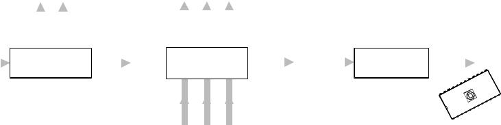
The essence of the conversion process is shown in Fig. 8.1. Here the program is prepared by the tame human in symbolic form, digested by the computer and output in machine-readable form. Of course this simple statement belies a rather more complex process, and we want to examine this in just enough detail to help you in writing your programs.
incf |
COUNT,f |
Translate |
00101010100000 |
|
|||
movf |
COUNT,w |
|
00100000100000 |
addlw |
6 |
|
11111000000110 |
btfsc |
STATUS,DC |
|
01100100000101 |
movwf |
COUNT |
|
00000010100000 |
return |
|
|
00000000001000 |
Fig. 8.1 Conversion from assembly-level source code to machine code.
In general the various translator and utility computer packages are written and sold by many software companies, and thus the actual details and procedures di er somewhat between the various commercial products. In the specific case of PIC MCU devices, Microchip Technology Inc. as a matter of policy has always provided their assembly-level software tools free of charge, a large factor in their popularity. For this reason commercial PIC software is relatively rare and what there is usually conforms to the Microchip syntax. For this reason we will illustrate this chapter with the Microchip suite of computer-aided coding tools.
Using the computer to aid in translating code from more user-friendly forms (known as source code) to machine-friendly binary code (known as object code or machine code and loading this into memory began in the late 1940s for mainframe computers. At the very least it permitted the use of higher-order number bases, such as hexadecimal.1 In this base the code fragment of Fig. 8.1 becomes:
0AA0
0820
3E06
1905
00A0
0008
A hexadecimal loader will translate this into binary and put the code in designated memory locations. This loader might be part of the software
1Actually base-8 (octal) was the popular choice for several decades.

8. Assembly language 199
in your PIC-EPROM programmer. Hexadecimal coding has little to commend it, except that the number of keystrokes is reduced – but there are more keys – and it is slightly easier to spot certain types of errors.
As a minimum, a symbolic translator, or assembler,2 is required for serious programming. This allows the programmer to use mnemonics for the instructions and internal registers, with names for constants, variables and addresses. The symbolic language used in the source code is known as assembly language. Unlike high-level languages, such as C or PASCAL, assembly language has a one-to-one relationship with the generated machine code, i.e. one line of source code produces one instruction. As an example, Program 8.1 shows a slightly modified version of Program 6.11 on page 163. This subroutine computes the square root of a 16-bit variable called NUM which has been allocated two bytes in the Data store.
Giving names to addresses and constants is especially valuable for longer programs, which may easily exceed 1000 lines. Together with the use of comments, this makes code easier to debug, develop and maintain. Thus, if we wished to alter the file registers holding the variable NUM from File 20:21h to, say, File 36:37h, then we need only alter the line:
cblock 20h
to:
cblock 36h
and then retranslate to machine code. In a program with, say, 50 references to the variable NUM, the alternative of altering all these addresses manually from 20h or 21h (high:low byte) to 36h or 37h respectively is laborious and error prone. In the body of our source code the high byte is referenced as NUM (that is the contents of File 20h) and the lower byte in File 21h as NUM+1, as assemblers can do simple arithmetic on symbolic constants – see page 223.
The pseudo instruction cblock is an example of an assembler directive. A directive is a command from the programmer to the assembler concerning its operation or giving a constant a name. We list a small subset of the Microchip assembler directives at the end of the chapter, on page 222; the reader should reference the o cial manual for a detailed description. Briefly the directives used in Program 8.1 are:
cblock - endc
Rather like a block of equ directives, giving the encapsulated list of label constants starting either at the specified value, eg. 20h, or following on from the last cblock if no address is given. Labelled entities can be deemed to occupy more than one byte by using a colon-delimited size field; for instance NUM:2 for a 2-byte allocation and are normally used to name General-Purpose registers (GPRs).
2The name is very old; it refers to the task of translating and assembling together the various modules making up a program.

200 The Quintessential PIC Microcontroller
Program 8.1 Absolute assembly-level code for our square-root module.
; Global declarations |
|
|||
STATUS |
equ |
3 |
; |
Status register is File 3 |
C |
equ |
0 |
; |
Carry/Not Borrow flag is bit0 |
|
cblock 20h |
Number: high byte, low byte |
||
|
NUM:2 |
|
; |
|
|
endc |
|
|
|
MAIN |
goto |
|
SQR_ROOT |
|
;************************************************************
;* FUNCTION: Calculates the square root of a 16-bit integer *
; * |
EXAMPLE |
: Number |
= FFFFh |
(65,535d), Root = FFh (255d) |
* |
|
; |
* |
ENTRY |
: Number |
in File |
NUM:NUM+1 |
* |
; |
* |
EXIT |
: Root in W. NUM:NUM+1; I:I+1 and COUNT altered |
* |
||
;************************************************************
;Local declarations
cblock
I:2, COUNT ; Magic number hi:lo byte & loop count endc
|
org |
200h |
; Code to begin @ 200h in Program store |
SQR_ROOT |
clrf |
COUNT |
; Task 1: Zero loop count |
|
clrf |
I |
; Task 2: Set magic number I to one |
|
clrf |
I+1 |
|
|
incf |
I+1,f |
|
; Task 3: DO |
|
|
|
SQR_LOOP |
movf |
I+1,w |
; Task 3(a): Number - I |
|
subwf |
NUM+1,f |
; Subtract lo byte I from lo byte Num |
|
movf |
I,w |
; Get high byte magic number |
|
btfss |
STATUS,C |
; Skip if No Borrow out |
|
addlw |
1 |
; Return borrow |
|
subwf |
NUM,f |
; Subtract high bytes |
; Task 3(b): IF |
underflow THEN exit |
||
|
btfss |
STATUS,C |
; IF No Borrow THEN continue |
|
goto |
SQR_END |
; ELSE the process is complete |
|
incf |
COUNT,f |
; Task 3(c): ELSE inc loop count |
|
movf |
I+1,w |
; Task 3(d): Add 2 to the magic number |
|
addlw |
2 |
|
|
btfsc |
STATUS,C |
; IF no carry THEN done |
|
incf |
I,f |
; ELSE add carry to upper byte I |
|
movwf |
I+1 |
|
|
goto |
SQR_LOOP |
|
SQR_END |
movf |
COUNT,w |
; Task 4: Return loop count as the root |
|
return |
|
|
|
end |
|
|
|
|
|
|
end
Tells the assembler that this is the end of the source code. equ
Associates a value to a symbol. For instance the assembler replaces the name STATUS by the value 3 anywhere it appears in an instruction operand. Normally used for Special-Purpose registers (SPRs) and bits within file registers.
8. Assembly language 201
org
Specifies the start address for following code otherwise the assembler defaults to 000h in the Program store. In this program the subroutine SQR_ROOT is originated at 200h.
Of course symbolic translators demand more computing power than simple hexadecimal loaders, especially in the area of memory and backup store. Prior to the introduction of personal computers in the late 1970s, either mainframe, minicomputers or special-purpose MPU/MCU development systems were required to implement the assembly process. Such implementations were inevitably expensive and inhibited the use of such computer aids, and hand-assembled coding was relatively common.
Translation software thus implements two tasks:
•Conversion of the various instruction mnemonics and labels to their machine-code equivalents.
•The location of the instructions and data in the appropriate memory location.
It is the second of these that is perhaps more di cult to understand. Program 8.2 is designed to be processed by an absolute assembler.
Here the programmer uses the directive org to tell the assembler to place the code in the specified Program store address. This means that the programmer needs to know where everything is to be placed. This absolute assembly process is shown in Fig. 8.2. Absolute assembly is adequate where a program is contained in a single self-contained file; which is the case for the majority of code in this text. However, real projects often consist of several thousand lines of code and require teamwork. With many modules being written by di erent people, perhaps also coming in from outside sources and libraries, some means must be found to link the appropriate modules together to give the one executable machine-code file. For example, you may have to call up a division subroutine that Fred has written some time ago. You will not know exactly where in memory this subroutine will reside until the project has been completed. What can you do? Well, a subroutine should have its entry point labelled; say, DIV in this case. You should be able to direct the assembler to give this label the attribute that its absolute value is to be found later by a linker program. We will look at this relocatable way of working later on in the chapter.
Most programs running on the lowand mid-range PICs are adequately handled by an absolute assembler. To clarify the process we will take the subroutine of Fig. 8.2 through from the creation of the source file to the final absolute machine-code file.
Editing
Initially the source file must be created using a text editor. A text editor di ers from a wordprocessor in that no embedded control codes, giving

202 The Quintessential PIC Microcontroller
y
Binary data/addresses
Absolute Machine-code file |
|
(Absolute Object code) |
|
||
|
||
|
|
|
 Errorfile
 Symbolfile
 Listingfile
Source file
memor Program
EPROM
 PIC
PIC
Fig. 8.2 Absolute assembly-level code translation.
formatting and other information, are inserted. For instance, there is no line wrapping; if you want a new line then you hit the [ENT] key. Most operating systems come with a simple text editor; for example, notepad for Microsoft’s Windows. Third-party products are also available and most wordprocessors have a text mode which can double as a program editor.3 Microchip-compatible assembly-level source files names have an extension .src.
3For example, some programs for this book were created using Wordstar 2000 in its non-document format.
8. Assembly language 203
The format of a typical line of source code looks like:
Label (optional) Destination operand
SQREND movf COUNT,w ; Copy into W
Instruction mnemonic Source operand Comment (optional)
With the exception of comment-only lines, all lines must contain an instruction (either executable by the MCU or a directive) and any relevant operand or operands. Any label must begin in column 1, otherwise the first character must be a space or a tab to indicate no label. A label can be up to 32 alphanumeric, underline or question mark characters with the proviso that the first character be an underline or letter. Labels are usually case sensitive. A line label names the Program store address of the first following executable instruction.
An optional comment is delineated by a semicolon, and whole-line comments are permitted – see lines 11–18 of Program 8.1. Comments are ignored by the assembler and are there solely for human-readable documentation. Notes should be copious and should explain what the program is doing, and not simply repeat the instruction. For example:
movf I,w |
; Move I into W |
is a waste of energy:
movf I,w |
; Get high byte of magic number |
is rather more worthwhile. Not, or minimally, commenting source code is a frequent failing, not confined to students. A poorly documented program is di cult to debug and subsequently to alter or extend. The latter is sometimes known as program maintenance.
Space should separate the instruction from any operand. Where there are two operands the source and destination fields are delineated by a comma. In instructions where the destination can be the Working register or the addressed file register, the predefined names w or f should appear in the destination fields or numbers 0 or 1 respectively. The assembler will default to destination file if omitted.
Assembling
The assembler program will scan the source file checking for syntax errors. If there no such errors the process goes on to translate to absolute object code; which is basically machine code with information concerning the location it is to be placed in Program memory. Syntax errors include such things as referring to labels that don’t exist or instructions that are not recognized. The output will include an error file giving any such errors. If there are no syntax errors, a listing file and machine-code file are generated.
In the case of our example the translation was invoked by entering:
204 The Quintessential PIC Microcontroller
mpasmwin /aINHX8M /e+ /l+ /c+ /rhex /p16f84 root.asm
where mpasmwin.exe is the name of the assembler program and root.asm is the specified source file. The flags are of the form /<option> and may be followed by + or - to enable or disable the option. Thus /e+ orders the production of an error file, /l+ likewise for a listing file, /c+ makes labels case sensitive, /rhex specifies the default base radix to be hexadecimal. The flag /p16f84 tells the assembler to treat the source file as pertaining to the PIC16F84 device. mpasmwin can translate code for all PIC devices; whether for 12-, 14or 16-bit cores.
The listing file shown in Table 8.1 reproduces the original source code, with the addition of the hexadecimal location of each instruction and its code. The values of any symbols (such as NUM which is listed as File 20h) is also itemized.
The listing file also provides a symbol table enumerating all symbols/labels defined in the program. The memory usage map gives a graphical representation of Program memory usage. Any warning messages are embedded in the file where they are applicable. For example, if the destination operand w or f is omitted the assembler will default to the latter and embed a warning message at that instruction in the listing file.
This file has only documentation value and is not executable by the processor.
Executable code
The concluding outcome of any translation process is the object file, sometimes known as the machine-code file. Once the specified code is in situ in the Program store, it may be run as the executable program.
As can be seen in Table 8.2, such files consist essentially of lines of hexadecimal digits representing the binary machine code, each preceded by the address of the first byte location of the line. This file can be used by the PIC programmer to put the code into Program ROM memory at the correct place. As the location of each code byte is explicitly specified, this type of file is known as absolute object code. The software component of the PIC programmer reading, deciphering and placing this code is sometimes called an absolute loader.
In the MPU/MCU world there are many di erent formats in common use. Although most of these de facto standards are manufacturerspecific, in the main they can be used for any brand of MPU/MCU. The format of the machine-code file shown here is known as 8-bit Intel hex and was specified with the flag /a INHEX8M.
Let us look at one of the lines in root.hex in more detail.
8. Assembly language 205
|
|
Start of data record marker |
|
|
|
|
|
|
||||
|
|
|
Byte |
address of |
first |
datum |
Machine |
code |
|
|||
: |
10 |
0400 |
00 |
|
|
|
|
|
|
3C |
||
A401 A201 |
A301 |
A30A |
2308 A102 |
2208 |
031C |
|
||||||
|
|
|
|
Record type = code record |
|
Checksum |
|
|||||
|
|
Number |
of bytes following marker |
|
|
|
|
|
||||
Table 8.1 The listing file root.lst. (continued next page).
Listing
MPASM 02.20 Released |
|
ROOT.ASM |
5-9-1999 14:18:12 |
PAGE 1 |
|
||||
LOC OBJECT CODE LINE SOURCE TEXT |
|
|
|
|
|||||
VALUE |
01 |
; Global declarations |
|
|
|
|
|||
|
|
|
|
|
|
||||
00000003 |
02 |
STATUS |
equ |
3 |
; Status register is File 3 |
|
|
||
00000000 |
03 |
C |
equ |
0 |
; Carry/Not Borrow flag is bit0 |
|
|||
|
|
04 |
|
|
|
|
|
|
|
|
|
05 |
|
cblock 20h |
|
|
|
|
|
00000020 |
06 |
|
NUM:2 |
; Number: high byte, low byte |
|
|
|||
|
|
07 |
|
endc |
|
|
|
|
|
0000 |
2A00 |
08 |
MAIN |
goto |
SQR_ROOT |
|
|
|
|
09 |
|
|
|
||||||
|
|
10 |
; *********************************************************** |
||||||
|
|
11 |
|||||||
|
|
12 |
; * FUNCTION: Calculates the square root of a 16-bit integer* |
||||||
|
|
13 |
; * EXAMPLE : Number = FFFFh (65,535d), Root = FFh (255d) |
* |
|||||
|
|
14 |
; * ENTRY |
: Number in File NUM:NUM+1 |
|
* |
|||
|
|
15 |
; * EXIT |
: Root in W. NUM:NUM+1; I:I+1 and COUNT altered * |
|||||
|
|
16 |
; *********************************************************** |
||||||
|
|
17 |
; Local declarations |
|
|
|
|
||
|
|
18 |
|
|
|
|
|||
|
|
19 |
|
cblock |
|
|
|
|
|
00000022 |
20 |
|
I:2, COUNT |
; Magic number hi:lo byte & loop count |
|||||
|
|
21 |
|
endc |
|
|
|
|
|
0200 |
|
22 |
|
org |
200h |
|
|
|
|
|
23 |
|
|
|
|
|
|||
0200 |
01A4 |
24 |
SQR_ROOT clrf |
COUNT |
; Task 1: Zero loop count |
|
|
||
|
|
25 |
|
|
|
|
|
|
|
0201 |
01A2 |
26 |
|
clrf |
I |
; Task 2: Set magic number I to one |
|
||
0202 |
01A3 |
27 |
|
clrf |
I+1 |
|
|
|
|
0203 |
0AA3 28 |
|
incf |
I+1,f |
|
|
|
|
|
|
|
29 |
|
|
|
|
|
|
|
|
|
30 |
; Task 3: DO |
|
|
|
|
|
|
0204 |
0823 |
31 |
SQR_LOOP movf |
I+1,w |
; Task 3(a): Number - I |
|
|
||
0205 |
02A1 |
32 |
|
subwf |
NUM+1,f ; Subtract lo byte I from lo byte Num |
||||
0206 |
0822 |
33 |
|
movf |
I,w |
; Get high byte magic number |
|
|
|
0207 |
1C03 |
34 |
|
btfss |
STATUS,C; Skip if No Borrow out |
|
|
||
0208 |
3E01 |
35 |
|
addlw |
1 |
; Return borrow |
|
|
|
0209 |
02A0 |
36 |
|
subwf |
NUM,f |
; Subtract high bytes |
|
|
|
|
|
37 |
|
|
|
|
|
|
|
|
|
38 |
; Task 3(b): IF |
underflow THEN exit |
|
|
|||
020A |
1C03 |
39 |
|
btfss |
STATUS,C; IF No Borrow THEN continue |
|
|
||
020B |
2A13 |
40 |
|
goto |
SQR_END ; ELSE the process is complete |
|
|||
|
|
41 |
|
|
|
|
|
|
|
020C |
0AA4 42 |
|
incf |
COUNT,f ; Task 3(c): ELSE inc loop count |
|
||||
|
|
43 |
|
|
|
|
|
|
|
020D |
0823 |
44 |
|
movf |
I+1,w |
; Task 3(d): Add 2 to the magic number |
|||
020E |
3E02 |
45 |
|
addlw |
2 |
|
|
|
|
020F |
1803 |
46 |
|
btfsc |
STATUS,C; IF no carry THEN done |
|
|
||
0210 |
0AA2 47 |
|
incf |
I,f |
; ELSE add carry to upper byte I |
|
|||
0211 |
00A3 |
48 |
|
movwf |
I+1 |
|
|
|
|
0212 |
2A04 |
49 |
|
goto |
SQR_LOOP |
|
|
|
|
|
|
50 |
|
|
|
|
|
|
|
0213 |
0824 |
51 |
SQR_END |
movf |
COUNT,w ; Task 4: Return loop count as root |
|
|||
0214 |
0008 |
52 |
|
return |
|
|
|
|
|
|
|
53 |
|
end |
|
|
|
|
|
206 The Quintessential PIC Microcontroller
Table 8.1: (continued). The listing file root.lst.
MPASM 02.20 Released |
ROOT.ASM |
5-9-1999 14:18:12 PAGE 2 |
SYMBOL TABLE |
|
|
LABEL |
VALUE |
|
C |
00000000 |
|
COUNT |
00000024 |
|
I |
00000022 |
|
MAIN |
00000000 |
|
NUM |
00000020 |
|
SQR_END |
00000213 |
|
SQR_LOOP |
00000204 |
|
SQR_ROOT |
00000200 |
|
STATUS |
00000003 |
|
__16F84 |
00000001 |
|
MEMORY USAGE MAP (’X’ = Used, |
’-’ = Unused) |
|
0000 |
: |
X--------------- |
---------------- |
---------------- |
-------------- |
0200 |
: |
XXXXXXXXXXXXXXXX |
XXXXX----------- |
---------------- |
-------------- |
All other memory blocks unused.
Program Memory Words Used: 22
Program Memory Words Free: 1002
Errors |
: |
0 |
|
|
|
Warnings : |
0 |
reported, |
0 |
suppressed |
|
Messages : |
0 |
reported, |
0 |
suppressed |
|
Table 8.2: The absolute 8-bit Intel format object-code file root.hex.
:02000000002AD4
:10040000A401A201A301A30A2308A1022208031C3C
:10041000013EA002031C132AA40A2308023E03186B
:0A042000A20AA300042A2408080021
:00000001FF
The loader recognizes that a record follows when the character : is received. The colon is followed by a 2-digit hexadecimal number representing the number of machine-code bytes in the record; 10h = 16d in this case. The next four hexadecimal digits represent the starting byte address 0400h. This is twice the PIC’s Program store address of 200h, as each instruction takes up two bytes. The following 2-digit number is 00h for a normal record and 01h for the end-of-file record – see the last line of Table 8.2. The core of the record is the machine code with each instruction taking two 2-digit hexadecimal bytes ordered low:high byte. The loader reads this lower byte first (eg. A4) and then ‘tacks on’ the upper byte (eg. 01h) giving a 12-, 14or 16-bit program word as appro-
8. Assembly language 207
priate to the target PIC core – eg. 01A4 for a 14-bit core clrf 24h.4 The final byte is known as a checksum. The checksum is calculated as the 2’s complement of the sum of all preceding bytes in the record; that is −sum. As a check-up on transmission accuracy, the loader adds up all received bytes including this checksum for each record. This received count should give zero if no download error has occurred.
Assemblers are very particular that the syntax is correct. If there are syntax errors5 then an error file will be generated. For example, if line 49 was mistakenly entered as:
got SQRLOOP
then the error file of Table 8.3 below is generated.
|
|
Table 8.3: The error file |
|
Warning[207] |
ROOT.ASM |
49 |
: Found label after column 1. (got) |
Error[122] |
ROOT.ASM |
49 |
: Illegal opcode (SQRLOOP) |
The assembler does not recognize got as an instruction or directive mnemonic and erroneously assumes that it is a label mistakenly not beginning in column 1. On this basis it assumes that SQRLOOP is an instruction/directive mnemonic and again does not recognize it.
Most assemblers allow the programmer to define a sequence of processor instructions as a macro instruction. Such macro instructions can subsequently be used in a similar manner to native instructions. For example, the following code defines a macro instruction called Delay_1ms6 that implements a 1 ms delay when executed on a PIC running with a 4 MHz crystal. The directive pair macro - endm is used to enclose the sequence of native instructions which will be substituted when the mnemonic Delay_1ms is used anywhere in the subsequent program. The mnemonic will be replaced by the assembler with the defined code. Note that this will be in-line code unlike calling up a subroutine.
4Locating the multi-byte code in memory in the Intel way, formatted low:high byte, is known as big-endian (high byte is in the higher memory location) whereas the low-endian arrangement is favored by amongst others, Motorola.
5If the assembler announces that there are no errors then there is a tendency to think that the program will work. Unfortunately a lack of syntax errors in no way guarantees that the program will do anything of the sort!
6I have capitalized the first letter of all macro instructions to distinguish them from native instructions.

208 The Quintessential PIC Microcontroller
Delay_1ms |
macro |
|
|
LOOP |
local |
|
|
|
movlw |
d’250’ |
; Count from 250d |
LOOP |
addlw |
-1 |
; Decrement |
|
btfss |
STATUS,Z |
; to zero |
|
goto |
LOOP |
|
|
endm |
|
|
|
|
|
|
Where labels are used within the body of the macro, they should be declared using the local directive. This means that any conflict with labels where a macro instruction is evoked more than once is avoided.
This example is unusual in that the ‘instruction’ did not have any operands. Like native instructions, macros can have one or more operands. To see how this is done, consider a macro instruction called Bnz for Branch if Not Zero.7 Thus the instruction Bnz NEXT causes execution to transfer to the specified label if the Z flag is zero, otherwise continue on as normal. The definition of Bnz is:
Bnz |
macro |
destination |
|
btfss |
STATUS,Z |
|
goto |
destination |
|
endm |
|
|
|
|
Macros can be of any arbitrary complexity and can have any number of comma separated operands. For example, Microchip have available a large number of macros implementing arithmetic operations such as 16 × 16 and 32 × 32 multiplication. However, extensive use of macros can make programs di cult to debug, especially when an apparently simple macro instruction hides a number of side e ects which alter register contents and flags. A frequent source of error is to precede a macro instruction with a skip instruction, intending to branch around it on some condition. As the macro instruction is in fact a structure of several native instructions, this skip will actually be into the middle of the macro – with dire consequences.
Macro definitions, whether commercial or/and in-house may be collected together as a single file and included in the user program using the include directive. Thus if your file is called mymacros.mac then the line at the beginning of your program
include "mymacros.mac"
will allow access by the programmer to all macro definitions in the file. The assembler will only generate machine code for any macro instruc-
7This is a native instruction for the PIC18CXXX family.
8. Assembly language 209
tions actually used by the program. Any macros defined in the included file but not used will have no e ect on the final machine code.
One of the major advantages of using an assembler over machine code programming is the use of names for the various file registers and bits therein; for example, INTCON instead of File 0Bh and GIE in place of 7. In code, such as Program 7.1 on page 181, these equivalences are listed at the head of the source code using equ directives. Although the GPRs will have name labels unique to the particular program, the SPRs and their constituent bits are the same for all programs targeted to a particular type of PIC. Microchip provide files for each PIC, listing all SPRs and bits which can be included in the program’s heading; for example
Table 8.4: Part of Microchip’s file p16f84.inc.
;This header file defines configurations, registers, and other
;useful bits of information for the PIC16F84 microcontroller.
;These names match the data sheets as closely as possible.
;----- |
Register Files |
------------------------------------------ |
|
INDF |
|
EQU |
H’0000’ |
TMR0 |
|
EQU |
H’0001’ |
PCL |
|
EQU |
H’0002’ |
STATUS |
|
EQU |
H’0003’ |
FSR |
|
EQU |
H’0004’ |
PORTA |
|
EQU |
H’0005’ |
PORTB |
|
EQU |
H’0006’ |
EEDATA |
|
EQU |
H’0008’ |
EEADR |
|
EQU |
H’0009’ |
PCLATH |
|
EQU |
H’000A’ |
INTCON |
|
EQU |
H’000B’ |
OPTION_REG |
EQU |
H’0081’ |
|
TRISA |
|
EQU |
H’0085’ |
TRISB |
|
EQU |
H’0086’ |
EECON1 |
|
EQU |
H’0088’ |
EECON2 |
|
EQU |
H’0089’ |
;----- |
STATUS Bits -------------------------------------------- |
|
|
IRP |
|
EQU |
H’0007’ |
RP1 |
|
EQU |
H’0006’ |
RP0 |
|
EQU |
H’0005’ |
NOT_TO |
|
EQU |
H’0004’ |
NOT_PD |
|
EQU |
H’0003’ |
Z |
|
EQU |
H’0002’ |
DC |
|
EQU |
H’0001’ |
C |
|
EQU |
H’0000’ |
;----- |
INTCON Bits -------------------------------------------- |
|
|
GIE |
|
EQU |
H’0007’ |
EEIE |
|
EQU |
H’0006’ |
T0IE |
|
EQU |
H’0005’ |
INTE |
|
EQU |
H’0004’ |
RBIE |
|
EQU |
H’0003’ |
T0IF |
|
EQU |
H’0002’ |
INTF |
|
EQU |
H’0001’ |
RBIF |
|
EQU |
H’0000’ |


8. Assembly language 213
|
Relocatable |
|
|
|
|
|
assembler |
|
|
|
rms.lst |
main.asm |
main.o |
|
|
||
|
|
|
|||
|
|
|
|||
|
|
|
Linker |
||
|
|
|
|||
sqr.asm |
|
sqr.o |
+ |
rms.hex |
|
|
|||||
|
|
|
|
|
rms.map |
|
|
|
|
|
|
root2.asm |
|
root2.o |
|
|
|
|
|
|
|||
|
|
|
Linker |
script |
|
|
|
|
|||
pic16f84.lkr
Fig. 8.4 Linking three source files to implement a root mean square program.
(a)Square NUM_1.
(b)Square NUM_2.
(c)Add NUM_12 + NUM_22
(d)Square root item (c).
2.Design of a subroutine to square a byte number in the Working register to give a double-byte outcome in two GPRs.
3.Design of a subroutine to evaluate the square root of a double-byte sum and return it in W.
The process based on this decomposition of the task is shown diagrammatically in Fig. 8.4.
The main function is shown in Program 8.2. The program commences with the Reset goto instruction and is located in the VECTORS code stream. From the MAIN label onwards, code is located in the TEXT code stream using the directive TEXT code. We see from the map file output by the linker in Table 8.6 that MAIN is located at 005h.
The main routine uses four variables located in general-purpose file. These are placed in uninitialized RAM with the directives udata and res. A single file register is reserved for each of the two input variables NUM_1 and NUM_2 respectively. Two bytes are reserved for SUM which is used to hold the sum NUM_1 + NUM_2. As this is to be the input for the subroutine SQR_ROOT, it is declared global at the end of the file. This means that the location is public, that is additional files that are linked together can use the label SUM by declaring it extern – i.e. external to the file. Variables not declared thus are ‘hidden’ from the outside world, i.e. are private (or local) variables. In this manner the directive extern at the head of Program 8.2 allows the main routine to call the subroutines SQR_ROOT and SQR without knowing in advance where they are. In the same way the variable SQUARE is used by subroutine SQR to return the square of the byte sent to it in W. Space for this is reserved in a GPR in subroutine SQR and its exact whereabouts is not known by main.asm but will be allocated later by the linker. From the map file of Table 8.6 it is finally located in File 11h.

214 The Quintessential PIC Microcontroller
Program 8.2 The main relocatable source file main.asm.
|
include |
"p16f84.inc" |
|
|
|
extern |
SQR_ROOT, SQR, SQUARE |
||
|
udata |
|
; |
Reserve static data |
NUM_1 |
res |
1 |
; |
The first number |
NUM_2 |
res |
1 |
; |
The second number |
SUM |
res |
2 |
; |
Two bytes HI:LO for the sum |
RMS |
res |
1 |
; |
One byte for the outcome |
VECTORS |
code |
|
|
|
|
goto |
MAIN |
; |
The Reset vector |
TEXT |
code |
|
|
|
MAIN |
movf |
NUM_1,w |
; |
Get Number 1 |
|
call |
SQR |
; |
Square it |
|
movf |
SQUARE+1,w |
; |
Get lower byte |
|
movwf |
SUM+1 |
; |
Is the low byte of sum |
|
movf |
SQUARE,w |
; |
Get upper byte |
|
movwf |
SUM |
; |
Is the high byte of sum |
|
movf |
NUM_2,w |
; |
Now get Number 2 |
|
call |
SQR |
; |
Square it |
|
movf |
SQUARE+1,w |
; |
Get lower byte |
|
addwf |
SUM+1,f |
; |
Add to the low byte of sum |
|
btfsc |
STATUS,C |
; |
Check if produces carry |
|
incf |
SUM,f |
; |
Add the carry |
|
movf |
SQUARE,w |
; |
Get upper byte |
|
addwf |
SUM,f |
; |
Add to the high byte of sum |
|
call |
SQR_ROOT |
; |
Work out the square root |
|
movwf |
RMS |
; |
which is the root mean square |
|
global |
SUM |
|
|
|
end |
|
|
|
|
|
|
|
|
The main body of the code follows the task list enumerated above. The value NUM_12 is placed in file registers SUM:SUM+1 to which the computed NUM_22 is added. The outcome is then used as input to subroutine SQR_ROOT to return the root-mean square byte in W. Finally this is copied to the file register named RMS, for which a single byte has been reserved in the Data stream.
The subroutine sqr.asm of Program 8.3 is based on the subroutine of Program 6.5 on page 152, which multiplies two byte numbers. In this case on entry the contents of the Working register are copied to a file register labelled X and a 16-bit version constructed in X_COPY_H:X_COPY_L. The shift and add algorithm then evaluates X × X = X2. These three file registers are allocated with the directive udata_ovr (OVeRlay Uninitialized

8. Assembly language 215
Program 8.3 The relocatable source file sqr.asm.
include "p16f84.inc"
;The SQR subroutine
;************************************************************
; * FUNCTION: |
Squares one byte to give a 2-byte result |
* |
|
; * EXAMPLE : |
X = 10h (16), SQUARE = 0100h (256) |
* |
|
; * ENTRY |
: |
X in W |
* |
; * EXIT |
: |
SQUARE:2 in shared uninitialized data |
* |
;************************************************************
;Static data
|
udata |
|
|
SQUARE |
res |
2 |
; High:Low byte of square |
; Local data |
|
|
|
|
udata_ovr |
|
|
X |
res |
1 |
; Place for X |
X_COPY_L res |
1 |
; Holds a copy of X |
|
X_COPY_H res |
1 |
; Copy X overflow hi byte |
|
TEXT |
code |
|
|
; Task 1: Zero double-byte |
square |
||
SQR |
clrf |
SQUARE |
|
|
clrf |
SQUARE+1 |
|
; Task 2: Copy and extend X to 16-bits |
|||
|
movwf |
X |
; Put X away into Data memory |
|
movwf |
X_COPY_L |
; Copy of X |
|
clrf |
X_COPY_H |
; and extend to double byte |
;Task 3: DO
; Task 3A: Shift X right once
SQR_LOOP bcf |
STATUS,C |
; |
Clear carry |
rrf |
X,f |
; |
Shift |
; Task 3B: IF Carry == 1 THEN add 16-bit shifted X to square
|
btfss |
STATUS,C |
; |
IF C |
== 1 THEN do addition |
|
goto |
SQR_CONT |
; |
ELSE |
skip this task |
|
movf |
X_COPY_L,w |
; |
DO addition |
|
|
addwf |
SQUARE+1,f |
; |
First the low bytes |
|
|
btfsc |
STATUS,C |
; |
IF no carry THEN do high bytes |
|
|
incf |
SQUARE,f |
; |
ELSE |
add carry |
|
movf |
X_COPY_H,w |
; Next |
the high bytes |
|
|
addwf |
SQUARE,f |
|
|
|
|
; Task 3C: |
Shift 16-bit copy |
of X right once |
||
SQR_CONT bcf |
STATUS,C |
; Zero |
Carry-in |
||
|
rlf |
X_COPY_L,f |
|
|
|
|
rlf |
X_COPY_H,f |
|
|
|
|
; WHILE X not zero |
|
|
|
|
|
movf |
X,f |
; Test |
multiplier for zero |
|
|
btfss |
STATUS,Z |
|
|
|
|
goto |
SQR_LOOP |
; IF not THEN go again |
||
FINI |
return |
|
; ELSE |
finished |
|
global SQUARE, SQR end
DATA). This is similar to udata but indicates to the linker that file registers allocated in this way can be reused by other modules. In the map file of Table 8.6 we see that X has been allocated File 13h as has I, a variable in subroutine SQR_ROOT – see Program 8.3. This makes more e cient use of available Data memory. Variables that are only alive within the subrou-

216 The Quintessential PIC Microcontroller
tine that they are declared in are known in the C language as automatic, as their space is automatically reallocated as needed. The situation where variable space is preserved is known as static. Global variables, such as SQUARE are always static. In this case the variable SQUARE is created by reserving two bytes using the udata directive. It is also published using the global directive, as is the name of the subroutine.
Program 8.4 The relocatable source file root2.asm.
|
include |
"p16f84.inc" |
||
|
extern |
SUM |
; The 2-byte number Hi:Lo |
|
; Local declarations |
|
|
||
|
udata_ovr |
|
|
|
I |
res 2 |
|
|
; Magic number hi:lo |
COUNT |
res 1 |
|
|
; Loop count |
TEXT |
code |
|
|
|
SQR_ROOT |
clrf |
COUNT |
; Task 1: Zero loop count |
|
|
clrf |
I |
|
; Task 2: Set magic number I to one |
|
clrf |
I+1 |
|
|
|
incf |
I+1,f |
|
|
SQR_LOOP |
movf |
I+1,w |
; Task 3(a): Number - I |
|
|
subwf |
SUM+1,f |
; Subtract lo byte I from lo byte Num |
|
|
movf |
I,w |
|
; Get high byte magic number |
|
btfss |
STATUS,C |
; Skip if No Borrow out |
|
|
addlw |
1 |
|
; Return borrow |
|
subwf |
SUM,f |
; Subtract high bytes |
|
|
btfss |
STATUS,C |
; IF No Borrow THEN continue |
|
|
goto |
SQR_END |
; ELSE the process is complete |
|
|
incf |
COUNT,f |
; Task 3(c): ELSE inc loop count |
|
|
movf |
I+1,w |
; Task 3(d): Add 2 to the magic number |
|
|
addlw |
2 |
|
|
|
btfsc |
STATUS,C |
; IF no carry THEN done |
|
|
incf |
I,f |
|
; ELSE add carry to upper byte I |
|
movwf |
I+1 |
|
|
|
goto |
SQR_LOOP |
|
|
SQR_END |
movf |
COUNT,w |
; Task 4: Return loop count as the root |
|
|
return |
|
|
|
|
global |
SQR_ROOT |
|
|
|
end |
|
|
|
|
|
|
|
|
8. Assembly language 217
The final source file of the trio is the subroutine coded in Program 8.4. This is virtually identical to the absolute equivalent described in Program 8.1. Comparing the two, the org directive has been replaced by TEXT code and cblock by udata_ovr for the automatic local data. The data is passed to the subroutine SQR_ROOT via the external 2-byte global variable SUM, space for which has been allocated in main.asm. The subroutine name SQR_ROOT is published as global to make it visible to main.asm.
Like all source files, root2.asm makes use of SPRs such as STATUS. For this reason the file p16f84.inc of Table 8.4 has been included at the head of the file. As this file comprises a set of equ directives, the names thus published are absolute and are not allocated or changed in any way by the linker. Thus the linker map of Table 8.6 does not list such fixed symbols. They are, however, enumerated in the listing file produced by the linker.
In order to link the three source files together, the linker program must be given a command line listing the names of the input object files output by the relocatable assembler, the linker command file and the names of the output map and machine-code file. In the case of our example this was:
mplink p16f84.lkr main.o sqr.o root2.o /m rms.map /o rms.hex
which names the output map file rms.map and the absolute machine-code file rms.hex.
For documentation purposes the linker generates a composite listing file, similar (but more comprehensive) to that of Table 8.1 and an optional map file. The map file of Table 8.6 shows two lists. The first displays information for each section. This includes its name, type, start address, whether the section resides in Program or Data memory and its size in bytes. The Program Memory Usage table shows that 62 bytes of Program memory is used, including the two bytes of the Reset vector goto instruction, or around 6% of the possible total.
The second table shows information about the symbols in the composite program. Each symbol’s location in either the Program or Data store is given together with the source file where it is defined. Global symbols are noted as extern. Local variables are all labelled static, including automatic reusable variables such as COUNT and X_COPY_H both
at File 15h.
The final outcome, shown in Table 8.7, is a normal executable machine code file. The format of this file is exactly as described for Table 8.2 and can be loaded into absolute Program memory and run in the normal way.
218 The Quintessential PIC Microcontroller
Table 8.6: The output linker map file rms.asm.
MPLINK v1.20.00, Linker |
|
|
|
|
Linker Map File - Created Sat Jun |
5 16:13:48 1999 |
|
||
|
Section |
Info |
|
|
Section |
Type |
Address |
Location Size(Bytes) |
|
--------- --------- --------- --------- --------- |
||||
VECTORS |
code |
0x0000 |
program |
0x0002 |
.cinit |
romdata |
0x0001 |
program |
0x0004 |
TEXT |
code |
0x0005 |
program |
0x0076 |
.udata |
udata |
0x000c |
data |
0x0007 |
.udata_ovr |
udata |
0x0013 |
data |
0x0003 |
Program Memory Usage |
|
Start |
End |
--------- |
--------- |
0x0000 |
0x0002 |
0x0005 |
0x003f |
62 out of 1024 program words used, memory utilization is 6
|
Symbols - Sorted by Name |
|
||
Name |
Address |
Location |
Storage |
File |
--------- |
--------- |
--------- |
--------- |
--------- |
FINI |
0x002a |
program |
static |
SQR.ASM |
MAIN |
0x0005 |
program |
static |
MAIN.ASM |
SQR |
0x0015 |
program |
extern |
SQR.ASM |
SQR_CONT |
0x0024 |
program |
static |
SQR.ASM |
SQR_END |
0x003e |
program |
static |
ROOT2.ASM |
SQR_LOOP |
0x001a |
program |
static |
SQR.ASM |
SQR_LOOP |
0x002f |
program |
static |
ROOT2.ASM |
SQR_ROOT |
0x002b |
program |
extern |
ROOT2.ASM |
COUNT |
0x0015 |
data |
static |
ROOT2.ASM |
I |
0x0013 |
data |
static |
ROOT2.ASM |
NUM_1 |
0x000c |
data |
static |
MAIN.ASM |
NUM_2 |
0x000d |
data |
static |
MAIN.ASM |
RMS |
0x0010 |
data |
static |
MAIN.ASM |
SQUARE |
0x0011 |
data |
extern |
SQR.ASM |
SUM |
0x000e |
data |
extern |
MAIN.ASM |
X |
0x0013 |
data |
static |
SQR.ASM |
X_COPY_H |
0x0015 |
data |
static |
SQR.ASM |
X_COPY_L |
0x0014 |
data |
static |
SQR.ASM |
Developing, testing and debugging software requires a large number of software tools, many of which we have discussed earlier, such as an editor, assembler and linker. In practice there are many other tools such as high-level language compilers (see Chapter 9), simulators and EPROM programmers; shown diagrammatically in Fig. 8.5. Setting up these tools and interacting on an individual basis can be quite complex, especially where products from various manufacturers are involved. In this latter


8. Assembly language 221
Fig. 8.6 MPLAB window showing files selected to assemble, link and simulate Program 8.4.
allows the user to reset the (simulated) PIC, set break points, single step or run continuously. During this process user-selected file registers or the whole of Data memory can be monitored, as can execution time. Of course simulated execution time by the PC will be several orders of magnitude slower than a real PIC.
Figure 8.7 shows the end result of a simulation of our example. In the Watch_1 window are shown the initial values for NUM_1 and NUM_2 of 05h and 08h. Values of variables in this window can be set up by the programmer by double-clicking on the variable address. The outcome √52 + 82 = 9 (to the nearest integer) is seen in the Watch window as the value of RMS. The Watch window is set from the Window menu. Just under this window is the Stop-watch window, which shows that the program took 292 cycles to execute with the given data, which for a 4 MHz crystal is 292 µs in real time. After resetting under the Debug menu, a breakpoint is set up at the last instruction in main.asm. This movwf RMS instruction is shown in the screen snapshot greyed out. The program can be ‘run’
by clicking on the Green Tra c Light icon  in the Simulation tool bar (second icon from the left) or from the Debug menu. The Red equivalent
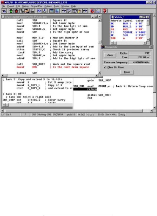
222 The Quintessential PIC Microcontroller
Fig. 8.7 MPLAB screen shot showing the programs selected in Fig. 8.6 being simulated.
 icon next left can be used to pause a run at any time. The
  icon is used to single step one instruction at a time.
Simulation will not catch all problems, especially those involving complex hardware/software interaction. However, over 95% of problems are caused by purely software design faults and simulation is good technique for testing and debugging such code.
For example, our code will fail if the total NUM_12 + NUM_22 > 65, 535, as SUM is only double-byte – see SAQ 8.5. Debugging should always at a first iteration try largest and smallest values of variables. However, correct operation is by no means guaranteed by this test for all possible combinations and sequences of input.
Finally, we review some general information specific to Microchip-compat- ible assemblers as an aid to reading programs in the rest of the book:
•Number representation.
–Hexadecimal: Denoted by a following h, eg. 41h, or a leading h with the number delineated by quotes, eg. h’41’ or a 0x prefix, eg. 0x41.

8. Assembly language 223
The latter is the prefix used in the C language to denote this number base.
The assembler normally defaults to this base so some programs show no hexadecimal indicators. However, it is better not to rely on the default behavior.
– Binary: Denoted by a leading b with a quote delimited number; eg. b’01000001’.
– Decimal: Denoted by a leading d with a quote delineated number; eg. d’65’ or a leading period prefix; eg. .65.
– ASCII: Denoted by a quote delimited character; eg. ’A’.
• Label arithmetic.
– Current position: $; eg. goto $+2.
– Addition: +; eg. goto LOOP+6.
– Subtraction: -; eg. goto LOOP-8.
– Multiplication: *; eg. subwf LAST*2.
– Division: /; eg. subwf LAST/2.
– Current position: $; eg. goto $+2.
• Directives.
– org: Places the following code in Program memory starting from the specified address; eg. org 0100h. Defaults to 000h. Can only be used for absolute assembly.
– code: Counterpart to org for relocatable assembly. The actual address of the code stream is defined in the linker’s command file. More than one code stream may be defined in the command file and in this case its name appears in the label field; eg. SUBROUTINES code.
– equ: Associates a value with a symbol; eg. PORTB equ 06. The
|
#define directive may be used instead; #define PORTB 06. |
|||
– |
cblock - endc: Used in absolute assembly to allocate program vari- |
|||
|
ables in Data memory; eg. |
|
|
|
|
|
|
|
|
|
cblock 20h |
|
|
|
|
FRED |
; One byte at 020h for FRED |
|
|
|
JIM:2 |
; Two bytes at 021:2h for JIM |
|
|
|
ARRAY:10 |
; Ten bytes for ARRAY at 023h - 02Ch |
|
|
|
endc |
|
|
|
|
|
|
||
|
The address is optional after the first cblock use. |
|
||
– |
udata: Counterpart to cblock for relocatable assembler. The start |
|||
|
address for this Data memory stream is in the linker’s script file. |
|||
|
There may be more than one Data stream defined in this script file |
|||
|
in which case its name is published in the label field; eg. |
|
||
|
SCRATCHPAD udata |
|
; Uninitialized data stream |
|
|
FRED |
res 1 ; Reserve one byte for FRED |
||
|
JIM |
res 2 |
; Reserve two bytes for JIM |
|
|
ARRAY |
res 10 |
; Reserve ten bytes for ARRAY |
|
–udata _ovr: OVeRlay Uninitialized DATA is similar to udata but the linker tries to reuse File registers for the specified named variables.
–res: Used with udata to REServe one or more bytes for a variable in the Data stream.

224 The Quintessential PIC Microcontroller
–extern: Publishes the named variables as defined outside the file, to be subsequently resolved by the linker.
–global: Publishes the named variables that have been defined (that is space reserved) in the file and that are to be made visible to the linker.
–macro - endm: Used to allow the specified enclosed sequence of instructions to be replaced by a new macro instruction; eg.
Addf macro N,file movf file,w addlw N movwf file endm
adds the literal N to the specified register file file. For example, to add five to File 20h the programmer can use the invocation
Addf 5,20h
–include: Used to include the specified file at this point; for example include "myfile.asm".
–end: Normally the last line of an assembly-level source file. Tells the assembler to ignore anything following.
Examples
Example 8.1
The following routine e ectively exchanges the byte contents of W and a file register F without needing an additional intermediate file register.
xorwf |
F,f |
; [file] |
<- |
WˆF |
|
xorwf |
F,w |
; |
W <- Wˆ(WˆF) = 0ˆF = F |
||
xorwf |
F,f |
; |
[file] |
<- |
FˆWˆF = 0ˆW = W |
|
|
|
|
|
|
where ˆ denotes eXclusive-OR.
Wrap the given code within a macro to generate a new instruction Exgwf F where F is the designated file register.
Solution
Exgwf macro |
file |
xorwf |
file,w |
xorwf |
file,f |
xorwf |
file,w |
endm |
|
|
|


|
|
|
8. Assembly language 227 |
|
|
|
|
movlw |
1 |
; |
The first literal |
banksel |
var_0 ; |
Change to the appropriate bank |
|
movwf |
var_0 ; |
Do it |
|
movlw |
10 |
; |
Literal ten |
banksel |
var_1 ; |
Change to the appropriate bank |
|
movwf |
var_1 ; |
Do it |
|
movlw |
100 |
; |
Literal hundred |
banksel |
var_2 ; |
Change to the appropriate bank |
|
movwf |
var_2 ; |
Do it |
|
|
|
|
|
Where Indirect addressing is used for 4-bank PICs the IRP bit in STATUS must be 0 for Banks 0:1 and 0 for Banks 2:3 – see page 113. This can be implemented using the bankisel directive in a similar manner to banksel.
Self-assessment questions
8.1Design macros to simulate the PIC18XXX family relative conditional Branch instructions bc (Branch on Carry) and bz (Branch if Zero).
8.2Design a macro of the form Mul XPLIER,XCAND,PRODUCT that will implement the function PRODUCT:2 = VAR1 × VAR2. Hint: Check Program 6.5 on page 152. What do you think are the advantages and disadvantages of using a macro instead of a subroutine in a long implementation like this?
8.3The goto and call instruction op-codes use an 11-bit address suitable to transfer anywhere within a 2 Kbyte Program store; as illustrated in Fig. 5.4 on page 114. As shown in this diagram, the 13-bit Program Counter is overwritten by the instruction’s 11-bit address together with PCLATH[4:3] (PCLATch High byte) File 0Ah to give a 13bit destination address.
Some mid-range PICs have a 4 or 8 Kbyte Program store, such as the PIC16C74 and PIC16F876 respectively. These require 12or 13bit destination addresses for goto and call instructions making use of the PCLATH[4:3] bits (see page 115) and e ectively partitioning up the Program store into corresponding two or four pages. The programmer needs to manipulate these bits before the goto or call instructions to specify the page. For instance, for the PIC16C74 to call a subroutine beginning at FRED which is at address 0B00h (i.e. in Page 1) we have:
228 The Quintessential PIC Microcontroller
bsf |
PCLATH,3 |
; |
Change to Page1 |
call |
FRED |
; |
Go to it |
|
|
|
|
In a relocatable program the location of a label, such as FRED is uncertain and in a multi-page PIC may be placed by the linker in any page. To allow the assembler to alter the PCLATH[4:3] bits as appropriate, Microchip compatible assemblers have a directive pagesel which must precede any goto or call instruction; rather in the manner of the banksel directive of Example 8.4. Show how you could use this to support a series of calls to subroutines named SUB_0, SUB_1 and SUB_2.
8.4The banksel approach to selecting a bank is ine cient in that an extra instruction is issued even if the PIC is already in the correct bank. Consider how in a timeor space-critical subroutine this ine ciency can be avoided.
8.5To be safe, determine a maximum value that NUM_1 and NUM_2 should not exceed to guarantee correct working for our program to calculate the root mean square of the two variables.
8.6Rewrite the routine main.asm of Program 8.2 and the subroutine root2.asm of Program 8.4 to allow for all values of NUM_1 and NUM_2. This will require a 3-byte sum and square root function.
8.7The following routine based on the macro instruction Movlf of Example 8.3 does not work as intended. COUNT is altered seemingly at random and not consistently with the desired literal 32. Why is this?
movf |
COUNT,f |
; Test COUNT for zero |
btfsc |
STATUS,Z |
; IF not Zero THEN skip |
Movlf |
d’32’,COUNT |
; ELSE re-initialize it to 32 |
|
|
|
8.8 A programmer with expertise in the Motorola 68HC05 MCU has been converted to the PIC family and wishes to design macros to simulate, amongst others, the following 68HC05 instructions. Note that the Accumulator register in the 68HC05 family is the equivalent to the Working register of the PIC.
lda memory
LoaD Accumulator with data from memory.
lda #data
LoaD Accumulator with literal data. sta memory
STore Accumulator data into memory.
8. Assembly language 229
tst memory
TeST memory for zero
tsta
TeST Accumulator for zero
Code suitable macros. Why do you think this approach might not be such a good idea?