

- •1.1 TODO LIST
- •2. PROGRAMMABLE LOGIC CONTROLLERS
- •2.1 INTRODUCTION
- •2.1.1 Ladder Logic
- •2.1.2 Programming
- •2.1.3 PLC Connections
- •2.1.4 Ladder Logic Inputs
- •2.1.5 Ladder Logic Outputs
- •2.2 A CASE STUDY
- •2.3 SUMMARY
- •2.4 PRACTICE PROBLEMS
- •2.5 PRACTICE PROBLEM SOLUTIONS
- •2.6 ASSIGNMENT PROBLEMS
- •3. PLC HARDWARE
- •3.1 INTRODUCTION
- •3.2 INPUTS AND OUTPUTS
- •3.2.1 Inputs
- •3.2.2 Output Modules
- •3.3 RELAYS
- •3.4 A CASE STUDY
- •3.5 ELECTRICAL WIRING DIAGRAMS
- •3.5.1 JIC Wiring Symbols
- •3.6 SUMMARY
- •3.7 PRACTICE PROBLEMS
- •3.8 PRACTICE PROBLEM SOLUTIONS
- •3.9 ASSIGNMENT PROBLEMS
- •4. LOGICAL SENSORS
- •4.1 INTRODUCTION
- •4.2 SENSOR WIRING
- •4.2.1 Switches
- •4.2.2 Transistor Transistor Logic (TTL)
- •4.2.3 Sinking/Sourcing
- •4.2.4 Solid State Relays
- •4.3 PRESENCE DETECTION
- •4.3.1 Contact Switches
- •4.3.2 Reed Switches
- •4.3.3 Optical (Photoelectric) Sensors
- •4.3.4 Capacitive Sensors
- •4.3.5 Inductive Sensors
- •4.3.6 Ultrasonic
- •4.3.7 Hall Effect
- •4.3.8 Fluid Flow
- •4.4 SUMMARY
- •4.5 PRACTICE PROBLEMS
- •4.6 PRACTICE PROBLEM SOLUTIONS
- •4.7 ASSIGNMENT PROBLEMS
- •5. LOGICAL ACTUATORS
- •5.1 INTRODUCTION
- •5.2 SOLENOIDS
- •5.3 VALVES
- •5.4 CYLINDERS
- •5.5 HYDRAULICS
- •5.6 PNEUMATICS
- •5.7 MOTORS
- •5.8 COMPUTERS
- •5.9 OTHERS
- •5.10 SUMMARY
- •5.11 PRACTICE PROBLEMS
- •5.12 PRACTICE PROBLEM SOLUTIONS
- •5.13 ASSIGNMENT PROBLEMS
- •6. BOOLEAN LOGIC DESIGN
- •6.1 INTRODUCTION
- •6.2 BOOLEAN ALGEBRA
- •6.3 LOGIC DESIGN
- •6.3.1 Boolean Algebra Techniques
- •6.4 COMMON LOGIC FORMS
- •6.4.1 Complex Gate Forms
- •6.4.2 Multiplexers
- •6.5 SIMPLE DESIGN CASES
- •6.5.1 Basic Logic Functions
- •6.5.2 Car Safety System
- •6.5.3 Motor Forward/Reverse
- •6.5.4 A Burglar Alarm
- •6.6 SUMMARY
- •6.7 PRACTICE PROBLEMS
- •6.8 PRACTICE PROBLEM SOLUTIONS
- •6.9 ASSIGNMENT PROBLEMS
- •7. KARNAUGH MAPS
- •7.1 INTRODUCTION
- •7.2 SUMMARY
- •7.3 PRACTICE PROBLEMS
- •7.4 PRACTICE PROBLEM SOLUTIONS
- •7.5 ASSIGNMENT PROBLEMS
- •8. PLC OPERATION
- •8.1 INTRODUCTION
- •8.2 OPERATION SEQUENCE
- •8.2.1 The Input and Output Scans
- •8.2.2 The Logic Scan
- •8.3 PLC STATUS
- •8.4 MEMORY TYPES
- •8.5 SOFTWARE BASED PLCS
- •8.6 SUMMARY
- •8.7 PRACTICE PROBLEMS
- •8.8 PRACTICE PROBLEM SOLUTIONS
- •8.9 ASSIGNMENT PROBLEMS
- •9. LATCHES, TIMERS, COUNTERS AND MORE
- •9.1 INTRODUCTION
- •9.2 LATCHES
- •9.3 TIMERS
- •9.4 COUNTERS
- •9.5 MASTER CONTROL RELAYS (MCRs)
- •9.6 INTERNAL RELAYS
- •9.7 DESIGN CASES
- •9.7.1 Basic Counters And Timers
- •9.7.2 More Timers And Counters
- •9.7.3 Deadman Switch
- •9.7.4 Conveyor
- •9.7.5 Accept/Reject Sorting
- •9.7.6 Shear Press
- •9.8 SUMMARY
- •9.9 PRACTICE PROBLEMS
- •9.10 PRACTICE PROBLEM SOLUTIONS
- •9.11 ASSIGNMENT PROBLEMS
- •10. STRUCTURED LOGIC DESIGN
- •10.1 INTRODUCTION
- •10.2 PROCESS SEQUENCE BITS
- •10.3 TIMING DIAGRAMS
- •10.4 DESIGN CASES
- •10.5 SUMMARY
- •10.6 PRACTICE PROBLEMS
- •10.7 PRACTICE PROBLEM SOLUTIONS
- •10.8 ASSIGNMENT PROBLEMS
- •11. FLOWCHART BASED DESIGN
- •11.1 INTRODUCTION
- •11.2 BLOCK LOGIC
- •11.3 SEQUENCE BITS
- •11.4 SUMMARY
- •11.5 PRACTICE PROBLEMS
- •11.6 PRACTICE PROBLEM SOLUTIONS
- •11.7 ASSIGNMENT PROBLEMS
- •12. STATE BASED DESIGN
- •12.1 INTRODUCTION
- •12.1.1 State Diagram Example
- •12.1.2 Conversion to Ladder Logic
- •12.1.2.1 - Block Logic Conversion
- •12.1.2.2 - State Equations
- •12.1.2.3 - State-Transition Equations
- •12.2 SUMMARY
- •12.3 PRACTICE PROBLEMS
- •12.4 PRACTICE PROBLEM SOLUTIONS
- •12.5 ASSIGNMENT PROBLEMS
- •13. NUMBERS AND DATA
- •13.1 INTRODUCTION
- •13.2 NUMERICAL VALUES
- •13.2.1 Binary
- •13.2.1.1 - Boolean Operations
- •13.2.1.2 - Binary Mathematics
- •13.2.2 Other Base Number Systems
- •13.2.3 BCD (Binary Coded Decimal)
- •13.3 DATA CHARACTERIZATION
- •13.3.1 ASCII (American Standard Code for Information Interchange)
- •13.3.2 Parity
- •13.3.3 Checksums
- •13.3.4 Gray Code
- •13.4 SUMMARY
- •13.5 PRACTICE PROBLEMS
- •13.6 PRACTICE PROBLEM SOLUTIONS
- •13.7 ASSIGNMENT PROBLEMS
- •14. PLC MEMORY
- •14.1 INTRODUCTION
- •14.2 MEMORY ADDRESSES
- •14.3 PROGRAM FILES
- •14.4 DATA FILES
- •14.4.1 User Bit Memory
- •14.4.2 Timer Counter Memory
- •14.4.3 PLC Status Bits (for PLC-5s and Micrologix)
- •14.4.4 User Function Control Memory
- •14.4.5 Integer Memory
- •14.4.6 Floating Point Memory
- •14.5 SUMMARY
- •14.6 PRACTICE PROBLEMS
- •14.7 PRACTICE PROBLEM SOLUTIONS
- •14.8 ASSIGNMENT PROBLEMS
- •15. LADDER LOGIC FUNCTIONS
- •15.1 INTRODUCTION
- •15.2 DATA HANDLING
- •15.2.1 Move Functions
- •15.2.2 Mathematical Functions
- •15.2.3 Conversions
- •15.2.4 Array Data Functions
- •15.2.4.1 - Statistics
- •15.2.4.2 - Block Operations
- •15.3 LOGICAL FUNCTIONS
- •15.3.1 Comparison of Values
- •15.3.2 Boolean Functions
- •15.4 DESIGN CASES
- •15.4.1 Simple Calculation
- •15.4.2 For-Next
- •15.4.3 Series Calculation
- •15.4.4 Flashing Lights
- •15.5 SUMMARY
- •15.6 PRACTICE PROBLEMS
- •15.7 PRACTICE PROBLEM SOLUTIONS
- •15.8 ASSIGNMENT PROBLEMS
- •16. ADVANCED LADDER LOGIC FUNCTIONS
- •16.1 INTRODUCTION
- •16.2 LIST FUNCTIONS
- •16.2.1 Shift Registers
- •16.2.2 Stacks
- •16.2.3 Sequencers
- •16.3 PROGRAM CONTROL
- •16.3.1 Branching and Looping
- •16.3.2 Fault Detection and Interrupts
- •16.4 INPUT AND OUTPUT FUNCTIONS
- •16.4.1 Immediate I/O Instructions
- •16.4.2 Block Transfer Functions
- •16.5 DESIGN TECHNIQUES
- •16.5.1 State Diagrams
- •16.6 DESIGN CASES
- •16.6.1 If-Then
- •16.6.2 Traffic Light
- •16.7 SUMMARY
- •16.8 PRACTICE PROBLEMS
- •16.9 PRACTICE PROBLEM SOLUTIONS
- •16.10 ASSIGNMENT PROBLEMS
- •17. OPEN CONTROLLERS
- •17.1 INTRODUCTION
- •17.3 OPEN ARCHITECTURE CONTROLLERS
- •17.4 SUMMARY
- •17.5 PRACTICE PROBLEMS
- •17.6 PRACTICE PROBLEM SOLUTIONS
- •17.7 ASSIGNMENT PROBLEMS
- •18. INSTRUCTION LIST PROGRAMMING
- •18.1 INTRODUCTION
- •18.2 THE IEC 61131 VERSION
- •18.3 THE ALLEN-BRADLEY VERSION
- •18.4 SUMMARY
- •18.5 PRACTICE PROBLEMS
- •18.6 PRACTICE PROBLEM SOLUTIONS
- •18.7 ASSIGNMENT PROBLEMS
- •19. STRUCTURED TEXT PROGRAMMING
- •19.1 INTRODUCTION
- •19.2 THE LANGUAGE
- •19.3 SUMMARY
- •19.4 PRACTICE PROBLEMS
- •19.5 PRACTICE PROBLEM SOLUTIONS
- •19.6 ASSIGNMENT PROBLEMS
- •20. SEQUENTIAL FUNCTION CHARTS
- •20.1 INTRODUCTION
- •20.2 A COMPARISON OF METHODS
- •20.3 SUMMARY
- •20.4 PRACTICE PROBLEMS
- •20.5 PRACTICE PROBLEM SOLUTIONS
- •20.6 ASSIGNMENT PROBLEMS
- •21. FUNCTION BLOCK PROGRAMMING
- •21.1 INTRODUCTION
- •21.2 CREATING FUNCTION BLOCKS
- •21.3 DESIGN CASE
- •21.4 SUMMARY
- •21.5 PRACTICE PROBLEMS
- •21.6 PRACTICE PROBLEM SOLUTIONS
- •21.7 ASSIGNMENT PROBLEMS
- •22. ANALOG INPUTS AND OUTPUTS
- •22.1 INTRODUCTION
- •22.2 ANALOG INPUTS
- •22.2.1 Analog Inputs With a PLC
- •22.3 ANALOG OUTPUTS
- •22.3.1 Analog Outputs With A PLC
- •22.3.2 Pulse Width Modulation (PWM) Outputs
- •22.3.3 Shielding
- •22.4 DESIGN CASES
- •22.4.1 Process Monitor
- •22.5 SUMMARY
- •22.6 PRACTICE PROBLEMS
- •22.7 PRACTICE PROBLEM SOLUTIONS
- •22.8 ASSIGNMENT PROBLEMS
- •23. CONTINUOUS SENSORS
- •23.1 INTRODUCTION
- •23.2 INDUSTRIAL SENSORS
- •23.2.1 Angular Displacement
- •23.2.1.1 - Potentiometers
- •23.2.2 Encoders
- •23.2.2.1 - Tachometers
- •23.2.3 Linear Position
- •23.2.3.1 - Potentiometers
- •23.2.3.2 - Linear Variable Differential Transformers (LVDT)
- •23.2.3.3 - Moire Fringes
- •23.2.3.4 - Accelerometers
- •23.2.4 Forces and Moments
- •23.2.4.1 - Strain Gages
- •23.2.4.2 - Piezoelectric
- •23.2.5 Liquids and Gases
- •23.2.5.1 - Pressure
- •23.2.5.2 - Venturi Valves
- •23.2.5.3 - Coriolis Flow Meter
- •23.2.5.4 - Magnetic Flow Meter
- •23.2.5.5 - Ultrasonic Flow Meter
- •23.2.5.6 - Vortex Flow Meter
- •23.2.5.7 - Positive Displacement Meters
- •23.2.5.8 - Pitot Tubes
- •23.2.6 Temperature
- •23.2.6.1 - Resistive Temperature Detectors (RTDs)
- •23.2.6.2 - Thermocouples
- •23.2.6.3 - Thermistors
- •23.2.6.4 - Other Sensors
- •23.2.7 Light
- •23.2.7.1 - Light Dependant Resistors (LDR)
- •23.2.8 Chemical
- •23.2.8.2 - Conductivity
- •23.2.9 Others
- •23.3 INPUT ISSUES
- •23.4 SENSOR GLOSSARY
- •23.5 SUMMARY
- •23.6 REFERENCES
- •23.7 PRACTICE PROBLEMS
- •23.8 PRACTICE PROBLEM SOLUTIONS
- •23.9 ASSIGNMENT PROBLEMS
- •24. CONTINUOUS ACTUATORS
- •24.1 INTRODUCTION
- •24.2 ELECTRIC MOTORS
- •24.2.1 Basic Brushed DC Motors
- •24.2.2 AC Motors
- •24.2.3 Brushless DC Motors
- •24.2.4 Stepper Motors
- •24.2.5 Wound Field Motors
- •24.3 HYDRAULICS
- •24.4 OTHER SYSTEMS
- •24.5 SUMMARY
- •24.6 PRACTICE PROBLEMS
- •24.7 PRACTICE PROBLEM SOLUTIONS
- •24.8 ASSIGNMENT PROBLEMS
- •25. CONTINUOUS CONTROL
- •25.1 INTRODUCTION
- •25.2 CONTROL OF LOGICAL ACTUATOR SYSTEMS
- •25.3 CONTROL OF CONTINUOUS ACTUATOR SYSTEMS
- •25.3.1 Block Diagrams
- •25.3.2 Feedback Control Systems
- •25.3.3 Proportional Controllers
- •25.3.4 PID Control Systems
- •25.4 DESIGN CASES
- •25.4.1 Oven Temperature Control
- •25.4.2 Water Tank Level Control
- •25.5 SUMMARY
- •25.6 PRACTICE PROBLEMS
- •25.7 PRACTICE PROBLEM SOLUTIONS
- •25.8 ASSIGNMENT PROBLEMS
- •26. FUZZY LOGIC
- •26.1 INTRODUCTION
- •26.2 COMMERCIAL CONTROLLERS
- •26.3 REFERENCES
- •26.4 SUMMARY
- •26.5 PRACTICE PROBLEMS
- •26.6 PRACTICE PROBLEM SOLUTIONS
- •26.7 ASSIGNMENT PROBLEMS
- •27. SERIAL COMMUNICATION
- •27.1 INTRODUCTION
- •27.2 SERIAL COMMUNICATIONS
- •27.2.1.1 - ASCII Functions
- •27.3 PARALLEL COMMUNICATIONS
- •27.4 DESIGN CASES
- •27.4.1 PLC Interface To a Robot
- •27.5 SUMMARY
- •27.6 PRACTICE PROBLEMS
- •27.7 PRACTICE PROBLEM SOLUTIONS
- •27.8 ASSIGNMENT PROBLEMS
- •28. NETWORKING
- •28.1 INTRODUCTION
- •28.1.1 Topology
- •28.1.2 OSI Network Model
- •28.1.3 Networking Hardware
- •28.1.4 Control Network Issues
- •28.2 NETWORK STANDARDS
- •28.2.1 Devicenet
- •28.2.2 CANbus
- •28.2.3 Controlnet
- •28.2.4 Ethernet
- •28.2.5 Profibus
- •28.2.6 Sercos
- •28.3 PROPRIETARY NETWORKS
- •28.3.1 Data Highway
- •28.4 NETWORK COMPARISONS
- •28.5 DESIGN CASES
- •28.5.1 Devicenet
- •28.6 SUMMARY
- •28.7 PRACTICE PROBLEMS
- •28.8 PRACTICE PROBLEM SOLUTIONS
- •28.9 ASSIGNMENT PROBLEMS
- •29. INTERNET
- •29.1 INTRODUCTION
- •29.1.1 Computer Addresses
- •29.1.2 Phone Lines
- •29.1.3 Mail Transfer Protocols
- •29.1.4 FTP - File Transfer Protocol
- •29.1.5 HTTP - Hypertext Transfer Protocol
- •29.1.6 Novell
- •29.1.7 Security
- •29.1.7.1 - Firewall
- •29.1.7.2 - IP Masquerading
- •29.1.8 HTML - Hyper Text Markup Language
- •29.1.9 URLs
- •29.1.10 Encryption
- •29.1.11 Compression
- •29.1.12 Clients and Servers
- •29.1.13 Java
- •29.1.14 Javascript
- •29.1.16 ActiveX
- •29.1.17 Graphics
- •29.2 DESIGN CASES
- •29.2.1 Remote Monitoring System
- •29.3 SUMMARY
- •29.4 PRACTICE PROBLEMS
- •29.5 PRACTICE PROBLEM SOLUTIONS
- •29.6 ASSIGNMENT PROBLEMS
- •30. HUMAN MACHINE INTERFACES (HMI)
- •30.1 INTRODUCTION
- •30.2 HMI/MMI DESIGN
- •30.3 DESIGN CASES
- •30.4 SUMMARY
- •30.5 PRACTICE PROBLEMS
- •30.6 PRACTICE PROBLEM SOLUTIONS
- •30.7 ASSIGNMENT PROBLEMS
- •31. ELECTRICAL DESIGN AND CONSTRUCTION
- •31.1 INTRODUCTION
- •31.2 ELECTRICAL WIRING DIAGRAMS
- •31.2.1 Selecting Voltages
- •31.2.2 Grounding
- •31.2.3 Wiring
- •31.2.4 Suppressors
- •31.2.5 PLC Enclosures
- •31.2.6 Wire and Cable Grouping
- •31.3 FAIL-SAFE DESIGN
- •31.4 SAFETY RULES SUMMARY
- •31.5 REFERENCES
- •31.6 SUMMARY
- •31.7 PRACTICE PROBLEMS
- •31.8 PRACTICE PROBLEM SOLUTIONS
- •31.9 ASSIGNMENT PROBLEMS
- •32. SOFTWARE ENGINEERING
- •32.1 INTRODUCTION
- •32.1.1 Fail Safe Design
- •32.2 DEBUGGING
- •32.2.1 Troubleshooting
- •32.2.2 Forcing
- •32.3 PROCESS MODELLING
- •32.4 PROGRAMMING FOR LARGE SYSTEMS
- •32.4.1 Developing a Program Structure
- •32.4.2 Program Verification and Simulation
- •32.5 DOCUMENTATION
- •32.6 COMMISIONING
- •32.7 REFERENCES
- •32.8 SUMMARY
- •32.9 PRACTICE PROBLEMS
- •32.10 PRACTICE PROBLEM SOLUTIONS
- •32.11 ASSIGNMENT PROBLEMS
- •33. SELECTING A PLC
- •33.1 INTRODUCTION
- •33.2 SPECIAL I/O MODULES
- •33.3 SUMMARY
- •33.4 PRACTICE PROBLEMS
- •33.5 PRACTICE PROBLEM SOLUTIONS
- •33.6 ASSIGNMENT PROBLEMS
- •34. FUNCTION REFERENCE
- •34.1 FUNCTION DESCRIPTIONS
- •34.1.1 General Functions
- •34.1.2 Program Control
- •34.1.3 Timers and Counters
- •34.1.4 Compare
- •34.1.5 Calculation and Conversion
- •34.1.6 Logical
- •34.1.7 Move
- •34.1.8 File
- •34.1.10 Program Control
- •34.1.11 Advanced Input/Output
- •34.1.12 String
- •34.2 DATA TYPES
- •35. COMBINED GLOSSARY OF TERMS
- •36. PLC REFERENCES
- •36.1 SUPPLIERS
- •36.2 PROFESSIONAL INTEREST GROUPS
- •36.3 PLC/DISCRETE CONTROL REFERENCES
- •37. GNU Free Documentation License
- •37.1 PREAMBLE
- •37.2 APPLICABILITY AND DEFINITIONS
- •37.3 VERBATIM COPYING
- •37.4 COPYING IN QUANTITY
- •37.5 MODIFICATIONS
- •37.6 COMBINING DOCUMENTS
- •37.7 COLLECTIONS OF DOCUMENTS
- •37.8 AGGREGATION WITH INDEPENDENT WORKS
- •37.9 TRANSLATION
- •37.10 TERMINATION
- •37.11 FUTURE REVISIONS OF THIS LICENSE
- •37.12 How to use this License for your documents
plc pid - 25.1
25. CONTINUOUS CONTROL
Topics:
•Feedback control of continuous systems
•Control of systems with logical actuators
•PID control with continuous actuators
•Analysis of PID controlled systems
•PID control with a PLC
•Design examples
Objectives:
•To understand the concepts behind continuous control
•Be able to control a system with logical actuators
•Be able to analyze and control system with a PID controller
25.1INTRODUCTION
Continuous processes require continuous sensors and/or actuators. For example, an oven temperature can be measured with a thermocouple. Simple decision-based control schemes can use continuous sensor values to control logical outputs, such as a heating element. Linear control equations can be used to examine continuous sensor values and set outputs for continuous actuators, such as a variable position gas valve.
Two continuous control systems are shown in Figure 25.1. The water tank can be controlled valves. In a simple control scheme, one of the valves is set by the process, but we control the other to maximize some control object. If the water tank was actually a city water tank, the outlet valve would be the domestic and industrial water users. The inlet valve would be set to keep the tank level at maximum. If the level drops there will be a reduced water pressure at the outlet, and if the tank becomes too full it could overflow. The conveyor will move boxes between stations. Two common choices are to have it move continuously, or to move the boxes between positions, and then stop. When starting and stopping the boxes should be accelerated quickly, but not so quickly that they slip. And, the conveyor should stop at precise positions. In both of these systems, a good control system design will result in better performance.

plc pid - 25.2
valve
q1
a) Water Tank
valve
q2 |
|
|
h |
|
|
|
|||
|
|
|||
|
|
|
|
|
|
|
|
|
|
motor
controller  Vin
Vin
b) Motor Driven Conveyor
Figure 25.1 Continuous Systems
A mechanical control system is pictured in Figure 25.2 that could be used for the water tank in Figure 25.1. This controller will adjust the valve position, therefore controlling the flow rate into the tank. The height of the fluid in the tank will change the hydrostatic pressure at the bottom of the tank. A pressure line is connected to a pressure cell. As the pressure inside the cell changes, the cell will expand and contract, opening and closing the valve. As the tank fills the pressure becomes higher, the cell expands, and the valve closes, reducing the flow in. The desired height of the tank can be adjusted by sliding the pressure cell up/down a distance x. In this example the height x is called the setpoint. The control variable is the position of the valve, and, the feedback variable is the water pressure from the tank. The controller is the pressure cell.

plc pid - 25.3
q1
Main water supply
q2
 x
x
 1. Feedback of hydrostatic pressure through a rubber tube.

 2. This input slider adjusts the position of the bellows (can
be adjusted with a screwdriver).


 3. Bellows expand/contract as pressure increases/decreases,
and move the rod that closes/opens the valve

 4. The valve changes the flow into the tank, thus changing the water height.
For control add,
feedback 1. Some means of measuring the water height (system state) setpoint
  2. Some input for desired control height
system error 
 3. Some error compensation
4. An actuator to change the system input
Figure 25.2 A Feedback Controller
Continuous control systems typically need a target value, this is called a setpoint. The controller should be designed with some objective in mind. Typical objectives are listed below.
fastest response - reach the setpoint as fast as possible (e.g., hard drive speed) smooth response - reduce acceleration and jerks (e.g., elevators)
energy efficient - minimize energy usage (e.g., industrial oven)
noise immunity - ignores disturbances in the system (e.g., variable wind gusts)
An engineer can design a controller mathematically when performance and stability are important issues. A common industrial practice is to purchase a PID unit, connect it
plc pid - 25.4
to a process, and tune it through trial and error. This is suitable for simpler systems, but these systems are less efficient and prone to instability. In other words it is quick and easy, but these systems can go out-of-control.
25.2 CONTROL OF LOGICAL ACTUATOR SYSTEMS
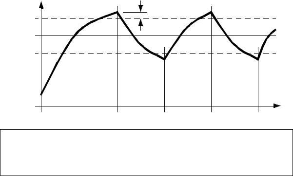
Many continuous systems will be controlled with logical actuators. Common examples include building HVAC (Heating, Ventilation and Air Conditioning) systems. The system setpoint is entered on a thermostat. The controller will then attempt to keep the temperature within a few degrees as shown in Figure 25.3. If the temperature is below the bottom limit the heater is turned on. When it passes the upper limit it is turned off, and it will stay off until if passes the lower limit. If the gap between the upper and lower the boundaries is larger, the heater will turn on less often, but be on for longer, and the temperature will vary more. This technique is not exact, and time lags will often lead to overshoot above and below the temperature limits.
upper |
room |
|
overshoot |
|
|
temp. |
|
|
|
||
temp. |
|
|
|
|
|
|
|
|
|
|
|
limit |
|
|
|
|
|
set temp. |
|
|
|
|
|
(nominal) |
|
|
|
|
|
lower |
|
|
|
|
|
temp. |
|
|
|
|
|
limit |
|
|
|
|
|
|
|
|
|
|
time |
heater on |
heater off |
heater on |
heater off |
heater on |
|
Note: This system turns on/off continuously. This behavior is known hunting. If the limits are set too close to the nominal value, the system will hunt at a faster rate. Therefore, to prevent wear and improve efficiency we normally try to set the limits as far away from nominal as possible.
Figure 25.3 Continuous Control with a Logical Actuator
Figure 25.4 shows a controller that will keep the temperature between 72 and 74