

plc wiring - 3.21
3.6SUMMARY
•PLC inputs condition AC or DC inputs to be detected by the logic of the PLC.
•Outputs are transistors (DC), triacs (AC) or relays (AC and DC).
•Input and output addresses are a function of the card location and input bit number.
•Electrical system schematics are documented with diagrams that look like ladder logic.
3.7PRACTICE PROBLEMS
1.Can a PLC input switch a relay coil to control a motor?
2.How do input and output cards act as an interface between the PLC and external devices?
3.What is the difference between wiring a sourcing and sinking output?
4.What is the difference between a motor starter and a contactor?
5.Is AC or DC easier to interrupt?
6.What can happen if the rated voltage on a device is exceeded?
7.What are the benefits of input/output modules?
8.(for electrical engineers) Explain the operation of AC input and output conditioning circuits.
9.What will happen if a DC output is switched by an AC output.
10.Explain why a stop button must be normally closed and a start button must be normally open.
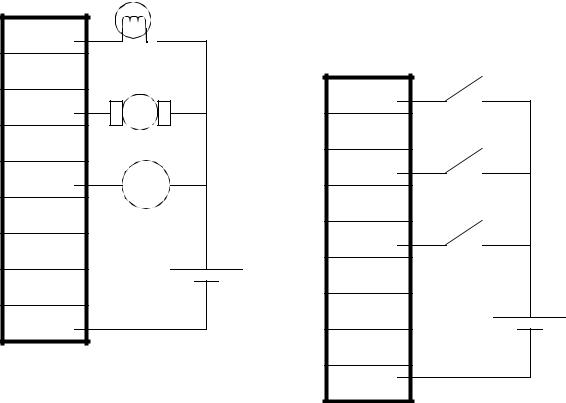
11.For the circuit shown in the figure below, list the input and output addresses for the PLC. If switch A controls the light, switch B the motor, and C the solenoid, write a simple ladder logic
plc wiring - 3.22
program.
200 |
|
|
201 |
|
|
202 |
|
|
203 |
|
|
204 |
solenoid |
|
valve |
||
|
||
205 |
|
|
206 |
+ |
|
|
||
207 |
24VDC |
|
|
||
com |
|
|
A |
100 |
|
101 |
|
102 |
B |
|
|
103 |
|
104 |
C |
|
|
105 |
|
106 |
+ |
107 |
12VDC |
com |
|
12.We have a PLC rack with a 24 VDC input card in slot 3, and a 120VAC output card in slot 2. The inputs are to be connected to 4 push buttons. The outputs are to drive a 120VAC lightbulb, a 240VAC motor, and a 24VDC operated hydraulic valve. Draw the electrical connections for the inputs and outputs. Show all other power supplies and other equipment/components required.
13.You are planning a project that will be controlled by a PLC. Before ordering parts you decide to plan the basic wiring and select appropriate input and output cards. The devices that we will use for inputs are 2 limit switches, a push button and a thermal switch. The output will be for a 24Vdc solenoid valve, a 110Vac light bulb, and a 220Vac 50HP motor. Sketch the basic wiring below including PLC cards.
14.Add three pushbuttons as inputs to the figure below. You must also select a power supply, and

plc wiring - 3.23
show all necessary wiring.
1
com
2
com
3
com
4
com
5
com
15. Three 120Vac outputs are to be connected to the output card below. Show the 120Vac source, and all wiring.
V
00
01
02
03
04
05
06
07
16.Sketch the wiring for PLC outputs that are listed below.
-a double acting hydraulic solenoid valve (with two coils)
-a 24Vdc lamp
-a 120 Vac high current lamp
-a low current 12Vdc motor

plc wiring - 3.24
3.8 PRACTICE PROBLEM SOLUTIONS
1.no - a plc OUTPUT can switch a relay
2.input cards are connected to sensors to determine the state of the system. Output cards are connected to actuators that can drive the process.
3.sourcing outputs supply current that will pass through an electrical load to ground. Sinking inputs allow current to flow from the electrical load, to the common.
4.a motor starter typically has three phases
5.AC is easier, it has a zero crossing
6.it will lead to premature failure
7.by using separate modules, a PLC can be customized for different applications. If a single module fails, it can be replaced quickly, without having to replace the entire controller.
8.AC input conditioning circuits will rectify an AC input to a DC waveform with a ripple. This will be smoothed, and reduced to a reasonable voltage level to drive an optocoupler. An AC output circuit will switch an AC output with a triac, or a relay.
9.an AC output is a triac. When a triac output is turned off, it will not actually turn off until the AC voltage goes to 0V. Because DC voltages don’t go to 0V, it will never turn off.
10.If a NC stop button is damaged, the machine will act as if the stop button was pushed and shut down safely. If a NO start button is damaged the machine will not be able to start.
11.
outputs: |
|
|
|
|
100 |
200 |
|
200 |
- light |
|
|
|
|
||
|
|
|
|
|
|||
202 |
- motor |
|
|
|
|
|
|
|
|
|
|
|
|
||
204 |
- solenoid |
|
|
|
|
|
|
|
|
|
|
|
|
||
inputs: |
|
|
|
|
102 |
202 |
|
|
|
||||||
100 |
- switch A |
|
|
|
|
|
|
|
|
|
|
|
|
||
102 |
- switch B |
|
|
|
|
|
|
104 |
- switch C |
|
|
|
|
|
|
|
|
|
|
|
|
104 |
210 |
|
|
|
|
||||
|
|
|
|
|
|
|
|
|
|
|
|
|
|
|
|

12.
13.
|
0 |
|
1 |
|
2 |
|
3 |
|
4 |
|
5 |
|
6 |
+ |
7 |
24VDC |
|
- |
com |
plc wiring - 3.25
0 |
|
0 |
1 |
|
1 |
2 |
|
2 |
3 |
|
3 |
4 |
|
4 |
5 |
|
5 |
6 |
|
6 |
7 |
+ |
7 |
|
24VDC |
|
com |
- |
com |
0 |
+ |
|
24Vdc |
||
|
||
1 |
- |
|
|
||
2 |
|
|
3 |
hot |
|
220Vac |
||
|
||
4 |
neut. |
|
|
||
5 |
|
|
6 |
hot |
|
120Vac |
||
7 |
neut. |
|
|
Note: relays are used to reduce the total number of output cards
|
plc wiring - 3.26 |
|
14. |
|
|
|
+ |
1 |
|
|
|
24Vdc |
|
com |
|
- |
2 |
|
|
com |
|
|
3 |
|
|
com |
|
|
4 |
|
|
com |
|
|
5 |
|
|
com |
15. |
|
|
V |
|
hot |
00 |
Load 1 |
120Vac |
01 |
Load 2 |
neut. |
|
|
02

 Load 3 03
04
05
06
07