

114 |
Aircraft Classification, Statistics, and Choices for Configuration |
passenger loading so that the longest in an aircraft family does not exceed the fineness ratio on the order of 13. The appropriate front and aft-end closure choices are then made. When the fuselage shell is established, the next task is to configure the interior for passenger and crew requirements. The flightcrew space in the forward closure (i.e., cockpit) and the pilot vision polar are then established. Inside the cabin, the crew and passenger requirements are approached simultaneously as integral requirements (e.g., seating, toilets, and galleys).
2.Wing Group. This is the most important component of the aircraft. The planform shape must be established and then sized for operational-field and flightperformance requirements. Options for high-lift devices are described in Section 3.12. Other smaller components (e.g., winglets) also are considered (see Section 3.21) but not all aircraft incorporate winglets.
3.Empennage Group. Choice, size, and placement result from the aircraft’s CG position and wing size. This book adheres to the conventional H-tail and V-tail configuration.
4.Nacelle Group. This topic is addressed in Chapter 10; only an outline for the shaping choice is provided herein.
These four groups of aircraft components provide the preliminary shaping of candidate aircraft configurations. After the wing-sizing and engine-matching exercises, the choice must be narrowed to one final configuration that offers the best compromise for the family variants to cover a wide market. The undercarriage is addressed separately in Chapter 7.
Iterations are required to position the empennage and undercarriage with respect to the wing because the CG position initially is not known. Weights are estimated from a provisional positioning and then the positions are fine tuned through iterations. (In a classroom exercise, one iteration is sufficient.)
4.7 Fuselage Group
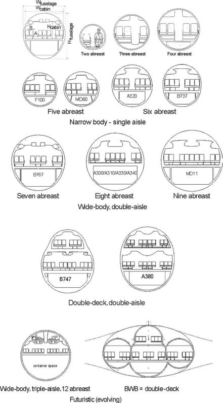
Fuselage geometry is determined from the designed passenger capacity (see Chapter 6). There are two parameters to size (i.e., fuselage width [W] and fuselage length [Lf]), which determine the constant-section fuselage-barrel length. In turn, this depends on the seat pitch and width for the desired passenger comfort level. Table 4.2 lists the statistics for existing designs – a new design would be similar. The width and length of the fuselage must be determined simultaneously, bearing in mind that the maximum growth potential in the family of variants cannot be too long or too short and keeping the fineness ratio from 7 to 14 (a good value is around 10). Boeing 757–300 records the highest fineness ratio of 14.7. A seating arrangement with two aisles results in more than six abreast (average diameter, Dave = [H + W]/2; see Figure 4.14).
4.7.1 Fuselage Width
The first parameter to determine for the fuselage average diameter is the number of abreast seating for passenger capacity. There is an overlap on choice for

4.7 Fuselage Group |
|
|
|
|
|
|
115 |
||
Table 4.2. Number of passengers versus number of abreast seating and fineness ratio |
|||||||||
|
|
|
|
|
|
|
|
||
|
|
|
|
|
|
|
|
||
Baseline |
Passenger |
Abreast |
Fuselage |
Length |
Fineness |
|
|
||
aircraft |
capacity |
seating |
Diaave -m |
m |
ratio |
Cross-section |
|||
|
|
|
|
|
|
|
|
|
|
Learjet45 |
6 (4 to 8) |
2 |
|
1.75 |
17.20 |
≈10.00 |
circular |
||
Dornier 228 |
18 |
2 |
|
|
|
≈ |
|
rectangular |
|
Dornier 328 |
24 |
3 |
|
2.20 |
20.92 |
≈ |
|
circular |
|
ERJ135 |
37 |
3 |
|
2.28 |
24.39 |
≈10.70 |
circular |
||
ERJ145 |
50 |
3 |
|
2.28 |
27.93 |
≈12.25 |
stretched version |
||
Canadair CL600 |
19 |
4 |
|
2.69 |
18.77 |
≈7.00 |
short fuselage |
||
Canadair RJ200 |
50 |
4 |
|
2.69 |
24.38 |
≈9.06 |
circular |
||
Canadair RJ900 |
86 |
4 |
|
2.69 |
36.16 |
≈13.44 |
stretched version |
||
Boeing 717–200 |
117 |
5 |
|
3.34 |
34.34 |
≈10.28 |
noncircular |
||
BAe145 (RJ100) |
100 |
5 |
|
3.56 |
30.00 |
≈8.43 |
|
|
|
Airbus 318 |
107 |
6 |
|
3.96 |
30.50 |
≈7.70 |
circular |
||
Airbus 321 |
185 |
6 |
|
3.96 |
44.00 |
≈11.10 |
circular |
||
Boeing 737–100 |
200 |
6 |
|
3.66 |
28.00 |
≈7.65 |
noncircular |
||
Boeing 737–900 |
200 |
6 |
|
3.66 |
42.11 |
≈11.50 |
family variant |
||
Boeing 757–300 |
230 |
6 |
|
3.66 |
54.00 |
≈14.70 |
highest ratio |
||
Boeing 767–300 |
260 |
7 |
|
5.03 |
53.67 |
≈10.70 |
circular |
||
Airbus 330–300 |
250 |
8 |
|
5.64 |
63.00 |
≈11.20 |
circular |
||
Airbus 340–600 |
380 |
8 |
|
5.64 |
75.30 |
≈13.35 |
circular |
||
Boeing 777–300 |
400 |
9 |
≈ |
6.20 |
73.86 |
≈11.90 |
circular |
||
Boeing 747–400 |
500 |
10 |
6.50 |
68.63 |
≈ |
10.55 |
partial double deck |
||
Airbus 380 |
600 |
10 |
≈ |
6.70 |
72.75 |
≈ |
10.80 |
full double deck |
|
|
|
||||||||
More than 450-passenger capacity, the fuselage cross-section becomes a double-deck arrangement due to current restrictions of fuselage length to 80 m (262.5 ft). In the future, this restriction could be relaxed.
the midrange capacity in the family of design; for example, an A330 with 240 to 280 passengers has seven-abreast seating whereas the same passenger capacity in a B767 has eight-abreast seating. When seating number is increased to more than six abreast, the number of aisles is increased to two to alleviate congestion in passenger movement. Because of the current fuselage-length limitation of 80 m, largercapacity aircraft have a double-deck arrangement (e.g., the B747 and the A380). It would be interesting to try a two-aisle arrangement with six-abreast seating that would eliminate a middle seat. A three-aisle arrangement with ten-abreast seating would eliminate the cluster of four seats together. A BWB would have more than two aisles; there is no reason to not consider a triple-deck arrangement.
Although a circular cross-section is the most desirable relative to stress (minimize weight) and manufacture (minimize cost), the market requirements for the below-cabin floorspace arrangement could result in a cross-section elongated to an oval or elliptical shape. The Boeing 747 with a more narrow upper-deck width is a unique oval shape in the partial length that it extends. This partial length of the upper deck helps cross-sectional area distribution (see Section 3.23) and area ruling.
Figures 4.12 and 4.13 show various options for aircraft fuselage cross-sections to accommodate different seating arrangements. All fuselage cross-sections are symmetrical to the vertical plane. In general, aircraft with four-abreast seating and more have space below the cabin floor for baggage and cargo.
116 |
Aircraft Classification, Statistics, and Choices for Configuration |
Figure 4.12. Typical commercial transport aircraft fuselage cross-section (not to scale)
4.7 Fuselage Group |
117 |
Figure 4.13. Typical choices for the wing–fuselage position
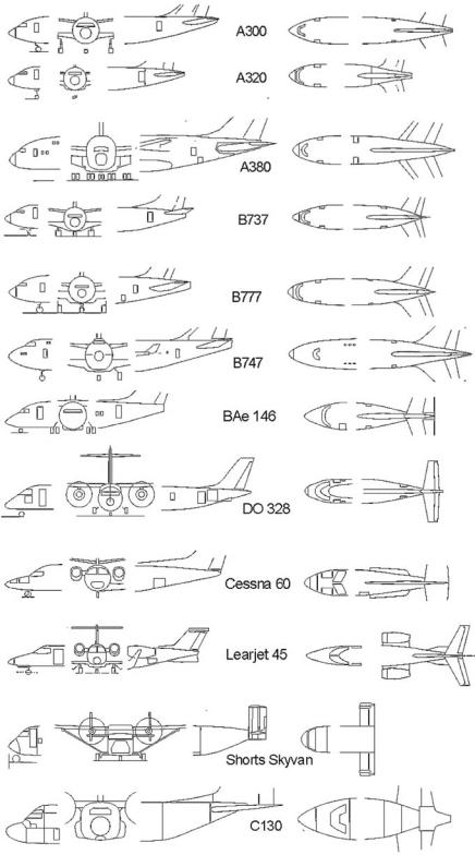
Unpressurized propeller-driven aircraft operating at lower altitudes can have rectangular cross-sections to reduce manufacturing costs, as well as offer more space (e.g., Shorts 360 aircraft). A pressurized fuselage cross-section would invariably be circular or nearly circular to minimize weight from the point of hoop-stress considerations. A two-abreast circular cross-section would have cramped legroom; a better option is a slightly widened lower lobe (e.g., Learjet 45) to accommodate legroom. In general, with a three-passenger capacity and more, the midsection fuselage has a constant cross-section with front and aft ends tailored to suit the requirements. The wing box arrangement for smaller aircraft should pass over (e.g., high-wing DO328) (Figure 4.13) or under (e.g., Learjet 45) the fuselage.
4.7.2 Fuselage Length
The overall fuselage length, L (see Figure 3.49) consists of the (1) nose cone, (2) constant cross-section midsection barrel, and (3) aft-end closure. The constant crosssection mid-fuselage length is established from the passenger seating arrangement and combined with the class arrangement (i.e., first class, business class, and economy/tourist class). Section 4.7.6 provides seat dimensions for the two main classes (i.e., business and economy).
Aircraft length may not be equal to fuselage length if any other part of the aircraft extends beyond the fuselage extremities (e.g., the tail sweep may go beyond the tail cone of the fuselage; see Figure 6.8). Figure 4.14 shows the fuselage geometry relationship to the number of passengers. The fuselage width increases in increments with the number of passenger-abreast seating, one seat width at a time. Because of passenger comfort, a designer selects options from the sensitivity study (i.e., drag and cost variations); the continuous line in Figure 4.14 represents a typical average value. The actual width is determined in Chapter 6.
4.7.3 Front (Nose Cone) and Aft-End Closure
The tear-drop-shaped streamlined closure of the fuselage at both ends of the constant midsection keeps the nose cone blunter than the gradually tapered aft cone, as shown in Figure 4.15.

118 |
Aircraft Classification, Statistics, and Choices for Configuration |
Figure 4.14. Passenger number versus fuselage length (courtesy of MacMasters)
Figure 4.15 illustrates the front fuselage closure (i.e., nose cone) length, Lf, enclosing the flight deck (i.e., pilot cockpit), followed by the constant-section payload (passengers, in this case) shell. Being in a favorable pressure gradient of the flow, it is blunter than the aft closure. The aft-fuselage closure (tail cone) length, La, encloses the rear pressure bulkhead with a gradual closure in an adverse pressure gradient and has some degree of upsweep. In the center, the rotated cross-sectional view of the fuselage is shown.
average diameter, Dave = (H + W)/2 |
|
front-fuselage closure ratio, Fcf = Lf/Dave (also known as the |
(4.2) |
nose fineness ratio) |
|
aft-fuselage closure ratio, Fca = La/Dave |
|
Figure 4.16 shows several examples of current types of commercial transport aircraft designs. Statistical values for the frontand aft-fuselage closure are summarized in Table 4.3.
The front-end closure of bigger aircraft appears to be blunter than on smaller aircraft because the nose cone is sufficiently spacious to accommodate pilot positioning and instrumentation. A kink appears in the windscreen mould lines of the
Figure 4.15. Front (nose cone) and aft-end closure
4.7 Fuselage Group |
119 |
Figure 4.16. Examples of several front and aft-end closure options (scale differs for each aircraft)

120 |
Aircraft Classification, Statistics, and Choices for Configuration |
|||||||||
Table 4.3. Fuselage closure parameters |
|
|
|
|
|
|
|
|
||
|
|
|
|
|
|
|
|
|
|
|
|
|
|
|
|
|
|
|
|
|
|
Aircraft |
L (m) |
D (m) |
H – (m) |
W – (m) |
H/W |
Lf/D |
La/D |
UA |
CA |
|
|
|
|
|
|
|
|
|
|
|
|
A300–600 (TA, TF, LW) |
53.62 |
5.64 |
5.64 |
5.64 |
1 |
2.60 |
3.103 |
5 |
9 |
|
A310–300 (TA, TF, LW) |
46.66 |
5.64 |
5.64 |
5.64 |
1 |
1.60 |
3.40 |
5 |
11 |
|
A320–200 (TA, TF, LW) |
37.57 |
3.96 |
3.96 |
3.96 |
1 |
1.50 |
3.40 |
4 |
8 |
|
A330–300 (TA, TF, LW) |
59.00 |
5.64 |
5.64 |
5.64 |
1 |
1.82 |
3.64 |
8 |
11 |
|
A340–600 (TA, TF, LW) |
59.39 |
5.64 |
5.64 |
5.64 |
1 |
1.60 |
3.32 |
8 |
9 |
|
A380 (TA, TF, LW) |
70.40 |
7.78 |
8.41 |
7.14 |
|
1.50 |
3.91 |
5 |
11 |
|
Boeing 737 (TA, TF, LW) |
31.28 |
3.95 |
4.11 |
3.79 |
|
1.10 |
2.80 |
7 |
15 |
|
Boeing 747 (TA, TF, LW) |
68.63 |
7.30 |
8.10 |
6.50 |
|
1.31 |
3.31 |
5 |
11 |
|
Boeing 757 (TA, TF, LW) |
46.96 |
4.05 |
4.00 |
4.10 |
|
1.64 |
2.91 |
6 |
13 |
|
Boeing 767 (TA, TF, LW) |
47.24 |
5.03 |
5.03 |
5.03 |
1 |
1.17 |
2.67 |
7 |
15 |
|
Boeing 777 (TA, TF, LW) |
63.73 |
6.20 |
6.20 |
6.20 |
1 |
1.23 |
2.85 |
7 |
13 |
|
MD11 (TA, TF, LW) |
58.65 |
6.02 |
6.02 |
6.02 |
1 |
1.45 |
2.82 |
5 |
13 |
|
Tupolev 204 (TA, TF, LW) |
46.10 |
3.95 |
3.80 |
4.10 |
|
1.46 |
2.96 |
5 |
9 |
|
Fokker 100 (TA, TF, LW) |
32.50 |
3.30 |
3.05 |
3.49 |
|
1.42 |
3.42 |
2 |
10 |
|
Dornier 728 (TA, TF, LW) |
27.03 |
2.56 |
2.05 |
3.25 |
|
1.34 |
2.60 |
5 |
13 |
|
Dornier 328 (RA, TF, LW) |
20.92 |
2.42 |
2.425 |
2.415 |
|
1.27 |
2.64 |
5 |
10 |
|
Dash8 Q400 (RA, TP, HW) |
25.68 |
2.07 |
2.03 |
2.11 |
|
1.71 |
3.22 |
4 |
9 |
|
Bae RJ85 (RA, TP, HW) |
28.55 |
3.56 |
3.56 |
3.56 |
1 |
1.46 |
2.62 |
4 |
12 |
|
Skyvan (RA, TP, HW) |
12.22 |
square |
2.20 |
2.20 |
|
0.95 |
2.00 |
9 |
0 |
|
Cessna 560 (BJ, TF, LW) |
15.79 |
5.64 |
5.64 |
5.64 |
1 |
2.05 |
2.91 |
2 |
8 |
|
Learjet 31A (BJ, TF, LW) |
x |
5.64 |
1.63 |
1.63 |
|
2.17 |
3.64 |
2 |
5 |
|
Cessna 750 (BJ, TF, LW) |
21.00 |
1.80 |
1.80 |
1.80 |
1 |
2.00 |
3.00 |
7 |
15 |
|
Cessna 525 (BJ, TF, LW) |
14.00 |
1.60 |
1.60 |
1.60 |
1 |
2.00 |
2.56 |
7 |
13 |
|
Learjet 45 (BJ, TF, LW) |
|
5.64 |
1.75 |
1.72 |
|
1.91 |
2.86 |
8 |
4 |
|
Learjet 60 (BJ, TF, LW) |
17.02 |
3.96 |
1.96 |
1.96 |
1 |
1.91 |
2.82 |
2 |
5 |
|
CRJ 700 (RA, TF, LW) |
|
2.69 |
2.69 |
2.69 |
1 |
1.60 |
3.15 |
5 |
12 |
|
ERJ 140 (RA, TF, LW) |
26.58 |
|
|
|
|
2.00 |
2.89 |
3 |
14 |
|
ERJ 170 (RA, TF, LW) |
29.90 |
3.15 |
3.35 |
2.95 |
|
1.56 |
2.67 |
3 |
13 |
|
C17 (MT, TF, HW) |
49.50 |
6.85 |
6.85 |
6.85 |
1 |
0.85 |
3.41 |
10 |
12 |
|
C130 (MT, TF, HW) |
34.37 |
4.33 |
4.34 |
4.32 |
|
0.95 |
2.56 |
9 |
12 |
|
Notes: |
|
|
TA – Transport aircraft |
LW – Low wing |
H – Fuselage height |
RA – Regional aircraft |
HW – High wing |
W – Fuselage width |
BJ – Business jet |
L – Fuselage length |
Lf – Front-closure length |
MT – Military transport |
D – Fuselage diameter |
Lf – Aft-closure length |
TF – Turbofan |
|
UA – Upsweep angle, deg |
TP – Turboprop |
|
CA – Closure angle, deg |
fuselage to fit flat glasses on a curved fuselage body; flat surfaces permit wiper installation and are less costly to manufacture. Some small aircraft have curved windscreens that permit smooth fuselage mould lines.
The aft-end closure is shallower to minimize airflow separation when the boundary layer becomes thicker. All fuselages have some upsweep for aircraft rotational clearances at takeoff. The difference in shaping is minor and is a result of the designer’s choice. Designers must configure a satisfactory geometry with attention to all operation and structural requirements (e.g., pilot vision polar [see Section 4.7.4], pressure bulkhead positions, and various doors). Table 4.4 lists typical guidelines for the fuselage frontand aft-end closure ratios; the range represents current statistical values.