


9.8 Semi-empirical Relations to Estimate Aircraft Component Parasite Drag |
273 |
which can be converted to CDpmin in terms of the aircraft wing area; that is:
[CDpmin]w = fw /SW |
(9.21) |
(Note: Omit the term CFwrough in Equation 9.20 if it is accounted for after computing fs for all components, as shown in Equation 9.27).
The same procedure is used to compute the parasite drag of the empennage, pylons, and so forth, which are considered to be wing-like lifting surfaces.
flifting surface = [(CF + CF supervel + CF press + CF inter |
|
+ CF other + CF rough), × Aw ]lift sur |
(9.22) |
which can be converted to: |
|
[CDpmin]lifting surface = flifting surface/Sw |
(9.23) |
9.8.3 Nacelle Drag
The nacelle requires different treatment, with the special consideration of throttledependent air flowing through as well as over it, like the fuselage. This section provides the definitions and other considerations needed to estimate nacelle parasite drag (see [2], [9], and [21]). The nacelle is described in Section 10.8.
The throttle-dependent variable of the internal flow passing through the turbofan engine affects the external flow over the nacelle. The dominant changes in the flow field due to throttle dependency are around the nacelle at the lip and aft end. When the flow field around the nacelle is known, the parasite drag estimation method for the nacelle is the same as for the other components but must also consider the throttle-dependent effects.
Civil aircraft nacelles are typically pod-mounted. In this book, only the long duct is considered. Military aircraft engines are generally buried in the aircraft shell (i.e., fuselage). A podded nacelle may be thought of as a wrapped-around wing in an axi-symmetric shape like that of a fuselage. The nacelle section shows aerofoillike sections in Figure 9.5; the important sources of nacelle drag are listed here (a short duct nacelle [see Figure 10.16] is similar except for the fan exhaust coming out at high speed over the exposed outer surface of the core nozzle, for which its skin friction must be considered):
Throttle-independent drag (external surface)
skin friction
wrapping effects of axi-symmetric body
excrescence effects (includes nonmanufacturing types such as cooling ducts)
Throttle-dependent drag
inlet drag (front end of the diffuser)
nacelle base drag (zero for an engine operating at cruise settings and higher)
boat-tail drag (curvature of the nozzle at the aft end of the nacelle)
Definitions and typical considerations for drag estimation associated with the flow field around an isolated long-duct podded nacelle (approximated to circular
274 |
Aircraft Drag |
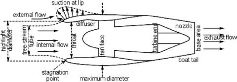
Figure 9.5. Aerodynamic considerations for an isolated long-duct nacelle drag
cross-section) are shown in Figure 9.5. Although there is internal flow through the nacelle, the external geometry of the nacelle may be treated as a fuselage, except that there is a lip section similar to the LE of an aerofoil. The prevailing enginethrottle setting is maintained at a rating for LRC or HSC for the mission profile. The intake drag and the base drag/boat-tail drag are explained next.
Intake Drag
The intake stream tube at cruise operates in a subcritical condition (see Section 10.8), which is complex and makes the intake-drag estimation difficult. There is spillage during the subcritical operation due to the stream tube being smaller than the cross-sectional area at the nacelle highlight diameter, where external flow turns around the lip creating suction (i.e., thrust). This can be considered precompression, ahead of the intake, when the intake velocity is slower compared to the free-stream velocity expressed in the fraction (Vintake/V∞). At (Vintake/V∞) < 0.8, the excess air flow spills over the nacelle lip. The intake lip acts as the LE of a circular aerofoil. The subcritical air-flow diffusion ahead of the inlet results in preentry drag called additive drag. The net effect results in spillage drag, as described herein. The spillage drag added to the friction drag at the lip results in the intake drag, which is a form of parasite drag. (For the military aircraft intake, see Section 9.17 and Chapter 10.)
spillage drag = additive drag + lip suction (thrust sign changes to -ve)
intake drag = spillage drag + friction drag at the lip (supervelocity effect)
Figure 9.6 shows intake-drag variations with the mass flow rate for both subsonic and supersonic (i.e., sharp LE) intake.
Base Drag
The design criteria for the nozzle-exit area sizing is such that at LRC, the exit-plane static pressure Pe equals the ambient pressure P∞ (a perfectly expanded nozzle, Pe, = P∞) to eliminate any base drag. At higher throttle settings, when Pe > P∞, there still is no base drag. At lower settings – for example, idle rating – there is some base drag as a result of the nozzle-exit area being larger than required.
Boat-Tail Drag
The long-duct contour for closure (i.e., “boat-tail” shape) at the aft end is shallow enough to avoid separation, especially with the assistance of entrainment effects of

9.8 Semi-empirical Relations to Estimate Aircraft Component Parasite Drag |
275 |
Figure 9.6. Throttle-dependent spillage drag
the exhaust plume. Hence, the boat-tail drag is kept low. At the idle throttle setting, considerable flow separation can occur and the magnitude of boat-tail drag would be higher, but it is still small compared to the nacelle drag.
For bookkeeping purposes and to avoid conflict with aircraft manufacturers, engine manufacturers generally include internal drag (e.g., ram, diffuser, and exhaust-pipe drag) in computing the net thrust of an engine. Therefore, this book only needs to estimate the parasite drag (i.e., external drag) of the nacelle. Intakeduct loss is considered engine-installation losses expressed as intake-recovery loss. Intakeand exhaust-duct losses are approximately 1 to 3% in engine thrust at LRC (throttleand altitude-dependent). The net thrust of the turbofan, incorporating installation losses, is computed using the engine-manufacturer–supplied program and data. These manufacturers work in close liaison to develop the internal contour of the nacelle and intake. External nacelle-contour design and airframe integration remain the responsibility of the aircraft manufacturer.
The long-duct nacelle characteristic length, Lnac, is the length measured from the intake-highlight plane to the exit-area plane. The wetted area AWn, Ren, and basic CFn are estimated as for other components. The incremental parasite drag formulae for the nacelle are provided herein. The supervelocity effect around the nacelle-lip section is included in the intake-drag estimation; hence, it is not computed separately. Similarly, the pressure effect is included in the base/boat-tail drag estimation. These two items are addressed this way because of the special consideration of throttle dependency. Following are the relationships used to compute the nacelle drag coefficient CDn:
1.CDn effects (same as the fuselage being axi-symmetric). Wrapping:
CFn = 0.025 × (diameter/length)−1 × Re−0.2 |
(9.24) |

276 |
|
|
|
Aircraft Drag |
|
|
Table 9.3. Nacelle interference drag (per nacelle) |
|
|
|
|
|
|
|
|
|
|
|
|
|
|
|
|
|
Wing-mounted |
|
Fuselage-mounted |
|
|
|
(Figure 9.7) |
Interference drag |
(Figure 9.7) |
Interference drag |
|
|
|
|
|
|
|
|
High (long) overhang |
0 |
Raised |
5% of CFn |
|
|
Medium overhang |
4% of CFn |
Medium |
5% of CFn |
|
|
Low (short) overhang |
7% of CFn |
Low |
5% of CFn |
|
|
|
|
S-duct |
6.5% of CFn |
|
|
|
|
Straight duct (center) |
5.8% of CFn |
|
|
|
|
|
|
|
2. Other incremental effects. Drag contributions made by the following effects are given in percentage of CFn. These are typical of the generic nacelle design:
(a) |
Intake drag at LRC – includes supervelocity effects ≈ 40 to 60% |
|
(higher BPR with higher percentage) |
(b) |
Boat-tail/base drag (throttle-dependent) – includes pressure effects ≈ 10 |
|
to 12% (higher value for smaller aircraft) |
(c) |
Excrescence (nonmanufacturing type such as cooling-air intakes) ≈ 20 to |
|
25% (higher value for smaller aircraft) |
3.Interference drag. A podded nacelle near the wing or body would have interference drag as follows (per nacelle). For a wing-mounted nacelle, the higher the overhang forward of the wing, the less would be the interference drag. Typical values of the interference drag by each pylon interacting with the wing or the body) are listed in Table 9.3.
4.Surface roughness (add later, ≈ 3%.) A long overhang in front of the wing keeps the nacelle free from any interference effects. A short overhang has the highest interference. However, there is little variation of interference drag of a nacelle mounted on a different position at the aft fuselage. Much depends on the proximity of other bodies, such as the wing and empennage. If the nacelle is within one diameter, then interference drag may be increased by another 0.5%. The center engine is close to the fuselage and with the V-tail, they have increased interference.
By totaling all the components, the flat-plate equivalent of the nacelle drag contribution is given by the following equation (omit the term CFn rough in Equation 9.25 if it is accounted for at the end, as shown in Equation 9.27):
fn = (CFn + CFn wrap + CFn intake + Cfn boat tail |
|
+ CFn excres + CFn rough) × Awn |
(9.25) |
Converting the nacelle contribution to CDpmin in terms of the aircraft wing area, it becomes:
[CDpmin]n = fn/SW |
(9.26) |
In the last three decades, the nacelle drag has been reduced by approximately twice as much as what has been achieved in other aircraft components. This demonstrates the complexity of and unknowns associated with the flow field around nacelles. CFD is important in nacelle design and its integration with aircraft.