

Thereʼs another physical reality to take into consideration in this situation that makes a real-world implementation of 802.11 perhaps not as immediately susceptible to poor performance in some locations as might be calculated. Weʼll discuss in detail later the fact that the RF wavefront doesnʼt conform to the free-space 3-dimensional shape and power distribution that would be calculated in theoretical terms. The environment is distorting the actual wavefront so that itʼs probable that the user will be in a zone that actually has more power than that contributed solely by the theoretical field pattern. Itʼs also possible that the user could have less power available to them than calculated. Reflection, refraction, and diffraction of the RF signal is taking place due to the various metal objects, walls, furniture, and other objects in the environment. Weʼll discuss in detail how metal objects influence wave propagation. A typical 802.11 office environment may contain metal file cabinets, metal window blinds, and perhaps metal shelving units. Even the metal in desk or floor lamps influences electromagnetic wave propagation, and, of course, donʼt forget all of the metal in the computers in the environment too. Nonetheless, using the polar coordinate signal strength graph is a fundamental starting point in antenna positioning and RF coverage planning.
RF Modeling and Simulation
Advanced computer modeling and simulation software is available that applies the formulas associated with electromagnetic wave propagation to the floor plan of a building or to an outdoor area. Using simulation tools allows prediction of antenna coverage to within +/- 2 dB, a very accurate measurement!
Any time an 802.11 network is being designed it can be very valuable to perform a predictive RF simulation of the space and see what the electromagnetic wave propagation patterns would really look like.
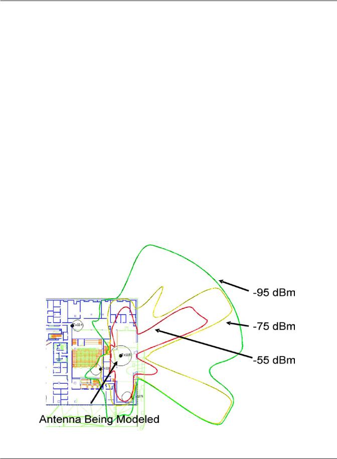
Figure 4.24 Results of an RF Simulation
Math and Physics for the 802.11 Wireless LAN Engineer |
49 |
Copyright 2003 - Joseph Bardwell

The wavefront coming from the antenna being modeled is shown at the -55, -75, and -95 dBm propagation boundaries. You can see how the signal extends out from the exterior of the building with the strong -55 and -75 dBm lobes passing through the glass doors and windows. To the left of the antenna there is a wide metal stairway that is effectively blocking the signal.
Unlike an antennaʼs polar coordinate graph, the pattern drawn by modeling and simulation software actually represents an RF propagation boundary and shows us what the field would really look like if we could see it with our eyes.
Math and Physics for the 802.11 Wireless LAN Engineer |
50 |
Copyright 2003 - Joseph Bardwell