


Figure 4.16 Antenna Field Pattern and Half Power Beam Width Measurement
Half-Power Beamwidth on a Polar Coordinate Graph
The Half-Power Beamwidth (HPBW) can be measured on a polar coordinate graph. There is a vertical HPBW (typically simply called the “vertical beamwidth”) measured on the Elevation Cut and a horizontal HPBW (typically simply called the “horizontal beamwidth”) measured on the Azimuth Cut. Since most indoor 802.11 applications confine their anticipated transmission areas to a single floor of a building the vertical beamwidth specification is sometimes ignored (although it should not be!). The horizontal beamwidth, taken from the Azimuth Cut, represents the field strength, relative to isotropic, as seen from a top view, which is just like looking at a floor plan.
Consider the Azimuth Cut shown below. Remember that this is a view-from-the-top. You first locate the point where the power is the greatest. In the example shown in Figure 4.17 (below), this is the point where the polar coordinate graph shows the maximum gain of 7 dB. Remember that a 3 dB reduction results in a 50% reduction in power. Studying the concentric circles on the graph you can see the 0 dB and 5 dB grids. Half-power is at 4 dB (because 7 dB minus 3 dB equals 4 dB). The points at which the field has decreased by 3 dB (hence, gone to half-power) define the Half-Power Beamwidth.
Figure 4.17 Identifying Half-Power Beamwidth (HPBW) Points
Math and Physics for the 802.11 Wireless LAN Engineer |
43 |
Copyright 2003 - Joseph Bardwell
Every directional antenna will include a “beamwidth” specification, which is actually the HalfPower Beam Width (HPBW) angle. When talking in terms of beamwidth, itʼs common to describe a horizontal beamwidth and a vertical beamwidth. The horizontal beamwidth comes from the Azimuth Cut and the vertical beamwidth comes from the Elevation Cut. When a directional antenna is mounted on a wall or pole itʼs common to point it slightly down. This can be accomplished by physically positioning the antenna in its mounting bracket or the manufacturer can build in a down angle. The down angle is provided so an antenna can be mounted flat against a surface but still aim its beam slightly downward. The figure below (4.18) shows how the polar coordinate representation of the signal strength and the beamwidth would appear.
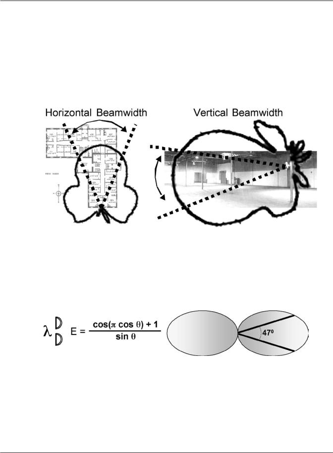
Figure 4.18 Horizontal and Vertical Beamwidth for a Directional Antenna
Fulland Half-Wavelength Antennae Beamwidth
Figure 4.19 (below) represents the field pattern for a 1-wavelength (λ) antenna. A 2.4 GHz 802.11 λ antenna would have a 12.5 cm radiating element, divided into two sub-elements making up the dipole structure. The signal would build up a pair of waves on the two dipole elements (as represented in the figure) giving rise to the “flattened” field pattern with a 47O HPBW.
Figure 4.19 The Field Pattern for a Full Wavelength Dipole Antenna
Figure 4.20 (below) shows the situation for a 1⁄2 λ antenna. This would be the 6.5 cm “shortie” antenna sometimes seen on 802.11 PCMCIA NICs. Notice how the beam width has spread out to 78O as a result of the way the wave is released from the two far ends of the dipole.
Math and Physics for the 802.11 Wireless LAN Engineer |
44 |
Copyright 2003 - Joseph Bardwell