

page 587
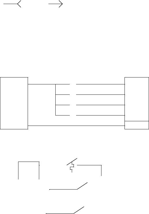
Female connector |
Male connector |
34.1.2 Wiring
• Discrete inputs - If a group of input voltages are the same, they can be grouped together. An example of this is shown below.
PLC Input
+ |
I0 |
|
I1 |
24VDC |
I2 |
|
|
|
I3 |
- |
COM. |
|
• If the input voltages are different and/or come from different sources, the user might use isolated inputs.
PLC Input Card
24VAC
|
|
COM |
|
|
|
|
|
|
|
|
|
|
|
I0 |
||
|
|
|
|
|
|
|
|
|
|
|
|
|
||||
|
|
|
|
|
|
|
|
|
|
|
|
|
|
|
|
N0 |
|
|
+ |
|
|
|
|||||||||||
|
|
|
|
|
|
|
|
|
|
|
|
I1 |
||||
|
|
|
|
|
|
|
|
|
|
|
|
|||||
|
|
24VDC |
|
|
|
|
|
|
|
|
|
|
||||
|
|
|
|
|
|
|
|
|
|
|
|
|
||||
|
|
- |
|
|
|
|
|
|
|
|
|
|
N1 |
|||
|
|
|
|
|
|
|
|
|
|
|
|
|
|
|
|
|
|
|
|
|
|
|
|
|
|
|
|
|
|
|
|
|
|
|
|
|
|
|
|
|
|
|
|
|
|
|
|
|
|
I2 |
|
+ |
|
|
|
||||||||||||
|
|
|
|
|
|
|
|
|
|
|
|
N2 |
||||
|
|
|
|
|
|
|
|
|
|
|
|
|||||
|
|
|
|
|
|
|
|
|
|
|
|
|||||
|
|
12VDC |
|
|
|
|
|
|
|
|
|
|
|
|
||
|
|
|
|
|
|
|
|
|
|
|
|
|
|
|||
|
- |
|
|
|
|
|
|
|
|
|
|
|
|
|||
|
|
|
|
|
|
|
|
|
|
|
|
|
||||
|
|
|
|
|
|
|
|
|
|
|
|
|
|
|
|
|
page 588
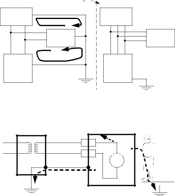
34.1.3 Shielding and Grounding
•There are two problems that occur in these systems,
1.Different power sources in the same system can cause different power supply voltages at opposite ends of a wire. As a result a current will flow, and an unwanted voltage appears. This can destroy components and create false signal levels.
2.Magnetic fields crossing the long conductors or in conductor loops can induce currents, and destroy equipment, give false readings, or add unwanted noise to analog data signals.
•Typical sources of grounding and shielding problems are,
-electrostatic
-magnetic
-electromagnetic
-resistance coupled circuits
-ground loops
•General shielding design points,
-choose a metal cabinet that will shield the control electronics
-avoid “noisy” equipment when possible
-separate voltage levels, and AC/DC wires from each other when possible.
-use shielded cables and twisted pair wires
•Grounding problems include,
-Resistance coupled devices can have interference through a common power source, such as power spikes or brownouts caused by other devices in a factory.
-Ground loops are caused when too many separate connections to ground are made creating loops of wire that become excellent receivers for magnetic interference that induces differences in voltage between grounds on different machines. The common solution is to use a common ground bar.
page 589
|
|
Preferred |
|
|
device A |
device A |
|||
|
ground loop #1 |
|
|
|
|
device B |
|
|
device B |
|
ground loop #2 |
+V |
gnd |
-V |
+V |
-V |
|||
power |
gnd |
power |
|
|
|
|
|||
supply |
|
supply |
|
|
- The case of an object should be tied to ground to give current a path to follow in the case of a fault that energizes the case. (Note: fuses or breakers will cut off the power, but the fault will be on for long enough to be fatal.)
e.g., wire break off |
and touches case |
Current can flow two ways, but most will follow the path of least resistance, good grounding will keep the worker relatively safe in the case of faults.
•Good grounding rules include,
-each PLC component should be grounded back to the main PLC chassis
-the ground wire should be separated from power wiring in enclosures
-use star washers to ensure good electrical connection
page 590
-mount ground wires on bare metal, remove paint if needed
-use 12AWG stranded copper for PLC equipment grounds and 8AWG stranded copper for enclosure backplate grounds
-connect the enclosure to the ground bus
-connect the machine ground to the enclosure ground
-the ground connection should have little resistance (<0.1 homs is good)
•Electrocution potential must be observed.
-Safe current levels are listed below. But be aware that in certain circumstances very low currents can kill, when in doubt, take no chances.
current in body (mA) |
effect |
0-1 |
negligible (5VDC) |
1-5 |
uncomfortable (24VDC) |
10-20 |
possibility for harm (120VAC) |
20-50 |
muscles contract (220VAC) |
50-100 |
pain, fainting, physical injuries |
100-300 |
heart fibrillates |
300+ |
burns, breathing stops, etc. |
-Step potential is another problem. Electron waves from a fault travel out in a radial direction through the ground. If a worker has two feet on the ground at different radial distances, there will be a potential difference between the feet that will cause a current to flow through the legs. The gist of this is - if there is a fault, don’t run/walk away/towards.
-Always ground systems first before applying power. (The first time a system is activated it will have a higher chance of failure.)
•Fail-safe wiring should be used so that if wires are cut or connections fail, the equipment should turn off. e.g., if a normally closed stop button is used, and the connector is broken off, it will cause the machine to stop, as if the stop button has been pressed, and brake the connection.
NO (Normally open) - When wiring switches or sensors that start actions, use normally open switches so that if there is a problem the process will not start.
NC (Normally Closed) - When wiring switches that stop processes use normally closed so that if they fail the process will stop. E-Stops must always be NC, and they must cut off the master power, not just be another input to the PLC.
•Other wiring notes,
-always use a master power relay that will shut down the process, and connect it to the E- stop system.
-use electrical wiring to handle all safety functions
-shutdown buttons must be easily accessible from all points around the machine