- •1. TABLE OF CONTENTS
- •2. BASIC MANUFACTURING
- •2.1 INTRODUCTION
- •2.2 PRACTICE PROBLEMS
- •3. MANUFACTURING COST ESTIMATING
- •3.1 COSTS ESTIMATES
- •3.2 COGS (COST OF GOODS SOLD)
- •3.3 VALUE ENGINEERING
- •3.4 REFERENCES
- •4. BASIC CUTTING TOOLS
- •4.1 CUTTING SPEEDS, FEEDS, TOOLS AND TIMES
- •4.2 HIGH SPEED MACHINING
- •4.3 REFERENCES
- •5. CUTTING THEORY
- •5.1 CHIP FORMATION
- •5.2 THE MECHANISM OF CUTTING
- •5.2.1 Force Calculations
- •5.2.1.1 - Force Calculations
- •5.2.1.2 - Merchant’s Force Circle With Drafting (Optional)
- •5.3 POWER CONSUMED IN CUTTING
- •5.4 PRACTICE QUESTIONS
- •5.5 TEMPERATURES IN CUTTING
- •5.6 TOOL WEAR
- •5.7 CUTTING TOOL MATERIALS
- •5.7.1 A Short List of Tool Materials
- •5.8 TOOL LIFE
- •5.8.1 The Economics of Metal Cutting
- •5.9 REFERENCES
- •5.10 PRACTICE PROBLEMS
- •6. SAWS
- •6.1 SPEEDS AND FEEDS
- •6.2 PRACTICE PROBLEMS
- •7. DRILLING
- •7.1 TYPES OF DRILL PRESSES
- •7.2 TYPICAL DRILL PRESS OPERATIONS
- •7.3 TYPICAL DRILL BITS
- •7.3.1 Reamers
- •7.3.2 Boring
- •7.3.3 Taps
- •7.4 DRILLING PROCESS PARAMETERS
- •7.4.1 The mrr For Drilling
- •7.5 PRACTICE PROBLEMS
- •8. LATHES
- •8.1 INTRODUCTION
- •8.2 OPERATIONS ON A LATHE
- •8.2.1 Machine tools
- •8.2.1.1 - Production Machines
- •8.3 LATHE TOOLBITS
- •8.3.1 Thread Cutting On A Lathe
- •8.3.2 Cutting Tapers
- •8.3.3 Turning Tapers on Lathes
- •8.4 FEEDS AND SPEEDS
- •8.4.1 The mrr for Turning
- •8.4.2 Process Planning for Turning
- •8.5 PRACTICE PROBLEMS
- •9. MILLING
- •9.1 INTRODUCTION
- •9.1.1 Types of Milling Operations
- •9.1.1.1 - Arbor Milling
- •9.1.2 Milling Cutters
- •9.1.3 Milling Cutting Mechanism
- •9.1.3.1 - Up-Cut Milling
- •9.1.3.2 - Down-Cut Milling
- •9.2 FEEDS AND SPEEDS
- •9.2.1 The mrr for Milling
- •9.2.2 Process Planning for Prismatic Parts
- •9.2.3 Indexing
- •9.3 PRACTICE PROBLEMS
- •10. GRINDING
- •10.1 OPERATIONS
- •10.2 MACHINE TYPES
- •10.2.1 Surface
- •10.2.2 Center
- •10.2.3 Centerless
- •10.2.4 Internal
- •10.3 GRINDING WHEELS
- •10.3.1 Operation Parameters
- •10.4 PRACTICE PROBLEMS
- •11. SURFACES
- •11.1 MEASURES OF ROUGHNESS
- •11.2 METHODS OF MEASURING SURFACE ROUGHNESS
- •11.2.1 Observation Methods
- •11.2.2 Stylus Equipment
- •11.2.3 Specifications on Drawings
- •11.3 OTHER SYSTEMS
- •11.4 PRACTICE PROBLEMS
- •11.4.0.1 - Roundness Testing
- •11.4.0.1.1 - Intrinsic Roundness Testing
- •11.4.0.1.2 - Extrinsic Roundness Testing
- •11.4.0.1.3 - Practice Problems
- •11.5 PRACTICE PROBLEMS
- •35. METROLOGY
- •35.1 INTRODUCTION
- •35.1.1 The Role of Metrology
- •35.2 DEFINITIONS
- •35.3 STANDARDS
- •35.3.1 Scales
- •35.3.2 Calipers
- •35.3.3 Transfer Gauges
- •35.4 INSTRUMENTS
- •35.4.1 Vernier Scales
- •35.4.2 Micrometer Scales
- •35.4.2.1 - The Principle of Magnification
- •35.4.2.2 - The Principle of Alignment
- •35.4.3 Dial Indicators
- •35.4.4 The Tool Makers Microscope
- •35.4.5 Metrology Summary
- •35.5 PRACTICE PROBLEMS
- •35.5.0.1 - Interferometry (REWORK)
- •35.5.0.1.1 - Light Waves and Interference
- •35.5.0.1.2 - Optical Flats
- •35.5.0.1.3 - Interpreting Interference Patterns
- •35.5.0.1.4 - Types of Interferometers
- •35.5.0.2 - Laser Measurements of Relative Distance
- •35.5.0.2.1 - Practice Problems
- •35.6 GAUGE BLOCKS
- •35.6.1 Manufacturing Gauge Blocks
- •35.6.2 Compensating for Temperature Variations
- •35.6.2.1 - References
- •35.6.3 Testing For Known Dimensions With Standards
- •35.6.3.1 - References
- •35.6.4 Odd Topics
- •35.6.5 Practice Problems
- •35.6.6 Limit (GO & NO GO) Gauges
- •35.6.6.1 - Basic Concepts
- •35.6.6.2 - GO & NO GO Gauges Using Gauge Blocks
- •35.6.6.3 - Taylor’s Theory for Limit Gauge Design
- •35.6.6.4.1 - Sample Problems
- •35.6.7 Sine Bars
- •35.6.7.1 - Sine Bar Limitations
- •35.6.7.1.1 - Practice Problems
- •35.6.8 Comparators
- •35.6.8.1 - Mechanical Comparators
- •35.6.8.2 - Mechanical and Optical Comparators
- •35.6.8.3 - Optical Comparators
- •35.6.8.4 - Pneumatic Comparators
- •35.6.9 Autocollimators
- •35.6.10 Level Gauges
- •35.6.10.1 - Clinometer
- •35.6.10.2 - The Brookes Level Comparator
- •35.6.11 The Angle Dekkor
- •35.7 MEASURING APARATUS
- •35.7.1 Reference Planes
- •35.7.1.1 - Granite Surface Plates
- •35.7.1.2 - Cast Iron Surface Plates
- •35.7.2 Squares
- •35.7.2.1 - Coordinate Measureing Machines
- •35.7.2.2 - Practice Problems
- •AM:35.7.3 Coordinate Measuring Machines (CMM)
- •36. ASSEMBLY
- •36.1 THE BASICS OF FITS
- •36.1.1 Clearance Fits
- •36.1.2 Transitional Fits
- •36.1.3 Interference Fits
- •36.2 C.S.A. B97-1 1963 LIMITS AND FITS(REWORK)
- •36.3 CSA MODIFIED FITS
- •36.4 CSA LIMITS AND FITS
- •36.5 THE I.S.O. SYSTEM
- •36.6 PRACTICE PROBLEMS
- •42. WELDING/SOLDERING/BRAZING
- •42.1 ADHESIVE BONDING
- •42.2 ARC WELDING
- •42.3 GAS WELDING
- •42.4 SOLDERING AND BRAZING
- •42.5 TITANIUM WELDING
- •42.5.1 Practice Problems
- •42.6 PLASTIC WELDING
- •42.7 EXPLOSIVE WELDING
- •42.7.1 Practice Problems
- •43. AESTHETIC FINISHING
- •43.1 CLEANING AND DEGREASING
- •43.2 PAINTING
- •43.2.1 Powder Coating
- •43.3 COATINGS
- •43.4 MARKING
- •43.4.1 Laser Marking
- •43.5 PRACTICE PROBLEMS
- •44. METALLURGICAL TREATMENTS
- •44.1 HEAT TREATING
- •44.2 ION NITRIDING
- •44.3 PRACTICE PROBLEMS
- •45. CASTING
- •45.1 SAND CASTING
- •45.1.1 Molds
- •45.1.2 Sands
- •45.2 SINGLE USE MOLD TECHNIQUES
- •45.2.1 Shell Mold Casting
- •45.2.2 Lost Foam Casting (Expandable Pattern)
- •45.2.3 Plaster Mold Casting
- •45.2.4 Ceramic Mold Casting
- •45.2.5 Investment Casting
- •45.3 MULTIPLE USE MOLD TECHNIQUES
- •45.3.1 Vacuum Casting
- •45.3.2 Permanent Mold Casting
- •45.3.2.1 - Slush Casting
- •45.3.2.2 - Pressure Casting
- •45.3.2.3 - Die Casting
- •45.3.3 Centrifugal Casting
- •45.3.4 Casting/Forming Combinations
- •45.3.4.1 - Squeeze Casting
- •45.3.4.2 - Semisolid Metal Forming
- •45.3.5 Single Crystal Casting
- •45.4 OTHER TOPICS
- •45.4.1 Furnaces
- •45.4.2 Inspection of Casting
- •45.5 Design of Castings
- •45.6 REFERENECES
- •45.7 PRACTICE PROBLEMS
- •46. MOLDING
- •46.1 REACTION INJECTION MOLDING (RIM)
- •46.1.1 References
- •46.2 INJECTION MOLDING
- •46.2.1 Hydraulic Pumps/Systems
- •46.2.2 Molds
- •46.2.3 Materials
- •46.2.4 Glossary
- •46.3 EXTRUSION
- •46.4 PRACTICE PROBLEMS
- •47. ROLLING AND BENDING
- •47.1 BASIC THEORY
- •47.2 SHEET ROLLING
- •47.3 SHAPE ROLLING
- •47.4 BENDING
- •48. SHEET METAL FABRICATION
- •48.1 SHEET METAL PROPERTIES
- •48.2 SHEARING
- •48.2.1 Progressive and Transfer Dies
- •48.2.2 DRAWING
- •48.3 DEEP DRAWING
- •48.4 SPINNING
- •48.5 MAGNETIC PULSE FORMING
- •48.6 HYDROFORMING
- •48.7 SUPERPLASTIC FORMING
- •48.7.1 Diffusion Bonding
- •48.8 PRACTICE PROBLEMS
- •49. FORGING (to be expanded)
- •49.1 PROCESSES
- •49.1.1 Open-Die
- •49.1.2 Impression/Closed Die
- •49.1.3 Heading
- •49.1.4 Rotary Swaging
- •50. EXTRUSION AND DRAWING
- •50.1 DIE EXTRUSION
- •50.1.1 Hot Extrusion
- •50.1.2 Cold Extrusion
- •50.2 HYDROSTATIC EXTRUSION
- •50.3 DRAWING
- •50.4 EQUIPMENT
- •50.5 PRACTICE PROBLEMS
- •51. ELECTROFORMING
- •51.1 PRACTICE PROBLEMS
- •52. COMPOSITE MANUFACTURING
- •52.1 FIBER REINFORCED PLASTICS (FRP)
- •52.2 COMPOSITE MANUFACTURING
- •52.2.1 Manual Layup
- •52.2.2 Automated Tape Lamination
- •52.2.3 Cutting of Composites
- •52.2.4 Vacuum Bags
- •52.2.5 Autoclaves
- •52.2.6 Filament Winding
- •52.2.7 Pultrusion
- •52.2.8 Resin-Transfer Molding (RTM)
- •52.2.9 GENERAL INFORMATION
- •52.2.10 REFERENCES
- •52.2.11 PRACTICE PROBLEMS
- •53. POWDERED METALLURGY
- •53.1 PRACTICE PROBLEMS
- •54. ABRASIVE JET MACHINING (AJM)
- •54.1 REFERENCES
- •54.2 PRACTICE PROBLEMS
- •55. HIGH PRESSURE JET CUTTING
- •56. ABRASIVE WATERJET CUTTING (AWJ)
- •57. ULTRA SONIC MACHINING (USM)
- •57.1 REFERENCES
- •57.1.1 General Questions
- •58. ELECTRIC DISCHARGE MACHINING (EDM)
- •58.1 WIRE EDM
- •58.2 PRACTICE PROBLEMS
- •58.3 REFERENCES
- •59. ELECTROCHEMICAL MACHINING (ECM)
- •59.1 REFERENCES
- •59.2 PRACTICE PROBLEMS
- •60. ELECTRON BEAM MACHINING
- •60.1 REFERENCES
- •60.2 PRACTICE PROBLEMS
- •61. ION IMPLANTATION
- •61.1 THIN LAYER DEPOSITION
- •61.2 PRACTICE PROBLEMS
- •62. ELECTROSTATIC SPRAYING
- •62.1 ELECTROSTATIC ATOMIZATION METHOD
- •62.2 PRACTICE PROBLEMS
- •63. AIR-PLASMA CUTTING
- •63.1 REFERENCES
- •63.2 PRACTICE PROBLEMS
- •64. LASER CUTTING
- •64.1 LASERS
- •64.1.1 References
- •64.2 LASER CUTTING
- •64.2.1 References
- •64.3 PRACTICE PROBLEMS
- •65. RAPID PROTOTYPING
- •65.1 STL FILE FORMAT
- •65.2 STEREOLITHOGRAPHY
- •65.2.1 Supports
- •65.2.2 Processing
- •65.2.3 References
- •65.3 BONDED POWDERS
- •65.4 SELECTIVE LASER SINTERING (SLS)
- •65.5 SOLID GROUND CURING (SGC)
- •65.6 FUSED DEPOSITION MODELLING (FDM)
- •65.7 LAMINATE OBJECT MODELING (LOM)
- •65.8 DIRECT SHELL PRODUCTION CASTING (DSPC)
- •65.9 BALLISTIC PARTICLE MANUFACTURING (BPM)
- •65.9.1 Sanders Prototype
- •65.9.2 Design Controlled Automated Fabrication (DESCAF)
- •65.10 COMPARISONS
- •65.10.1 References
- •65.11 AKNOWLEDGEMENTS
- •65.12 REFERENCES
- •65.13 PRACTICE PROBLEMS
- •66. PROCESS PLANNING
- •66.1 TECHNOLOGY DRIVEN FEATURES
- •66.2 MOST SIGNIFICANT FEATURE FIRST
- •66.3 DATABASE METHODS
- •66.4 MANUFACTURING VOLUMES
- •66.5 STANDARD PARTS
- •66.6 PRACTICE PROBLEMS
- •66.6.1 Case Study Problems
- •66.6.1.1 - Case 1
- •66.7 REFERENCES
page 171
35.6 GAUGE BLOCKS
•The purpose of gauge blocks are to provide linear dimensions known to within a given tolerance.
•The requirements of gauge blocks are,
-the actual size must be known
-the faces must be parallel
-the surface must have a smooth finish
-the surfaces must be flat
•most gauge blocks are made by normal techniques, but the high accuracy is obtained by a process called lapping (discussed later)
•The materials gauge blocks are made from are selected for,
-hardness
-temperature stability
-corrosion resistance
-high quality finish
•type of gauge blocks
-rectangular
-hoke (square)
•there are four grades of blocks,
-reference (AAA) - high tolerance (± 0.00005mm or 0.000002”)
-calibration (AA) (tolerance +0.00010mm to -0.00005mm)
-inspection (A) (tolerance +0.00015mm to -0.0005mm)
-workshop (B) - low tolerance (tolerance +0.00025mm to -0.00015mm)
•Original gauge block sets had lower tolerances and had a total of 91 pieces with values, 0.010” to 0.100” in 0.001” steps
•An 81 piece set of gauge block was developed by Johansson(s??) and is capable of covering wider ranges of dimensions.
0.1001” to 0.1009” in 0.0001” steps 0.1010” to 0.1490” in 0.0010” steps 0.0500” to 0.9500” in 0.0500” steps 1.0000”, 2.0000”, 3.0000”, 4.0000” blocks (2 wear blocks at 0.0500”)
•An 83 piece set has also been developed and it has the values (in inches),
page 172
<0.001” divisions |
|
|
|
|
|
|
|
|
|
0.1001 |
0.1002 |
0.1003 |
0.1004 |
0.1005 |
0.1006 |
0.1007 |
0.1008 |
0.1009 |
|
|
|
|
|
|
|
|
|
|
|
|
|
|
|
|
|
|
|
|
|
0.001” divisions |
|
|
|
|
|
|
|
|
|
0.101 |
0.102 |
0.103 |
0.104 |
0.105 |
0.106 |
0.107 |
0.108 |
0.109 |
0.110 |
0.111 |
0.112 |
0.113 |
0.114 |
0.115 |
0.116 |
0.117 |
0.118 |
0.119 |
0.120 |
0.121 |
0.122 |
0.123 |
0.124 |
0.125 |
0.126 |
0.127 |
0.128 |
0.129 |
0.130 |
0.131 |
0.132 |
0.133 |
0.134 |
0.135 |
0.136 |
0.137 |
0.138 |
0.139 |
0.140 |
0.141 |
0.142 |
0.143 |
0.144 |
0.145 |
0.146 |
0.147 |
0.148 |
0.149 |
|
|
|
|
|
|
|
|
|
|
|
|
|
|
|
|
|
|
|
|
|
0.05” divisions |
|
|
|
|
|
|
|
|
|
0.050 |
0.100 |
0.150 |
0.200 |
0.250 |
0.300 |
0.350 |
0.400 |
0.450 |
0.500 |
0.550 |
0.600 |
0.650 |
0.700 |
0.750 |
0.800 |
0.850 |
0.900 |
0.950 |
|
|
|
|
|
|
|
|
|
|
|
1” divisions |
|
|
|
|
|
|
|
|
|
1.000 |
2.000 |
3.000 |
4.000 |
|
|
|
|
|
|
|
|
|
|
|
|
|
|
||
|
|
|
|
|
|
|
|
||
two 0.050” wear blocks |
|
|
|
|
|
|
|
||
|
|
|
|
|
|
|
|
|
|
• The metric set has 88 gauge blocks (in mm),
page 173
<0.01mm divisions |
|
|
|
|
|
|
|
|
|
1.001 |
1.002 |
1.003 |
1.004 |
1.005 |
1.006 |
1.007 |
1.008 |
1.009 |
|
|
|
|
|
|
|
|
|
|
|
|
|
|
|
|
|
|
|
|
|
0.01mm divisions |
|
|
|
|
|
|
|
|
|
1.01 |
1.02 |
1.03 |
1.04 |
1.05 |
1.06 |
1.07 |
1.08 |
1.09 |
1.10 |
1.11 |
1.12 |
1.13 |
1.14 |
1.15 |
1.16 |
1.17 |
1.18 |
1.19 |
1.20 |
1.21 |
1.22 |
1.23 |
1.24 |
1.25 |
1.26 |
1.27 |
1.28 |
1.29 |
1.30 |
1.31 |
1.32 |
1.33 |
1.34 |
1.35 |
1.36 |
1.37 |
1.38 |
1.39 |
1.40 |
1.41 |
1.42 |
1.43 |
1.44 |
1.45 |
1.46 |
1.47 |
1.48 |
1.49 |
|
|
|
|
|
|
|
|
|
|
|
|
|
|
|
|
|
|
|
|
|
0.5mm divisions |
|
|
|
|
|
|
|
|
|
0.5 |
1.0 |
1.5 |
2.0 |
2.5 |
3.0 |
3.5 |
4.0 |
4.5 |
5.0 |
5.5 |
6.0 |
6.5 |
7.0 |
7.5 |
8.0 |
8.5 |
9.0 |
9.5 |
|
|
|
|
|
|
|
|
|
|
|
1cm divisions |
|
|
|
|
|
|
|
|
|
10 |
20 |
30 |
40 |
50 |
60 |
70 |
80 |
90 |
|
|
|
|
|
|
|
|
|
|
|
two 2mm wear blocks
•Most gauge block sets include thin wear blocks that should be included at the ends of a gauge block stack to protect the other gauge blocks.
•How to select gauge blocks for an application
page 174
from the 81 piece set above, build a stack that is 2.5744”
2.5744” |
|
||
-0.1004” |
|
||
|
|
|
|
2.4740” |
|
||
-0.1000” |
|
||
|
|
|
|
2.3740” |
therefore the gauge blocks are, |
||
-0.1240” |
0.1004” |
||
|
|
||
2.2500” |
2 wear blocks @ 0.0500” |
||
0.1240” |
|||
-0.2500” |
|||
0.2500” |
|||
|
|
||
|
|
||
2.0000” |
2.0000” |
||
-2.0000” |
|
||
|
|
|
|
0” |
|
•To assemble a gauge block stack,
1.remove the gauge blocks required from the protective case
2.clean of the oil that they have been coated in using a special cleaner. It is acceptable to handle the blocks, in fact the oil from your hands will help them stick together.
3.one at a time, hold the blocks so that the faces just overlap, push the blocks together, and slide them until the faces overlap together. This will create a vacuum between the blocks that makes them stick together (this process is known as wringing).
4.Make required measurements with the gauge blocks, being careful not to damage the faces
5.take the blocks apart, and apply the protective coating oil, and return them to their box.
•When using gauge blocks, minimze the number used. Each block will have tolerance errors, and as the stack of blocks becomes larger, so does the error.
•Do not leave gauge blocks wrung together for long periods of time.
35.6.1 Manufacturing Gauge Blocks
•The basic sequence of operations is,
1.machine to basic size
2.harden blocks and stress relieve
3.grind to size
4.lap (8 blocks at a time) to obtain tight tolerance
•Johansson’s procedure to make the first set (????)
page 175
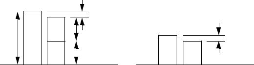
1.make a block with a 100mm length
2.Make two 50mm blocks
3.Determine the actual size of the 50mm blocks by comparing the difference in height
0.0004mm
100mm |
B |
50mm |
0.0002mm
A |
50mm |
B |
A |
A + B = 100 - 0.0004 = 99.9996mm
A - B = -0.0002mm
2A + B - B = 99.9996 - 0.0002 = 99.9994mm
A = 49.9947mm
B = 49.9949mm
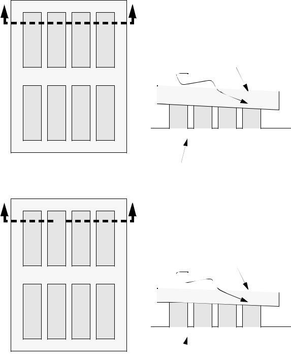
•Lapping is basically,
1.a porous pad is charged with a find grit powder. the excess powder is removed.
2.the parts to be lapped are secured to a surface plate magnetically (The positions are as shown below.
3.the lapping plate is placed on the block, and moved about, wearing down the blocks.
4.the lapping plate is removed, and the blocks are repositioned on the surface plate (as shown below) and the process is repeated.
5.The blocks are removed from the surface plate, and now are generally the same height.
page 176
A |
|
|
|
A |
|
|
|
1 |
3 |
5 |
7 |
In the first lap, there are 8 blocks magnetically |
|||
attached to the surface plate. The result is that |
|||||||
|
|
|
|
the blocks take on a slight angle as shown below |
|||
|
|
|
|
for a few of the blocks. |
|
|
|
2 |
4 |
6 |
8 |
|
|
|
lapping plate |
|
|
|
|
misaligned by alpha |
|
|
|
9 |
11 |
13 |
15 |
|
|
|
|
|
|
|
|
1 |
3 |
5 |
7 |
10 |
12 |
14 |
16 |
|
|
|
|
|
|
|
|
|
|
|
section A-A |
|
|
|
|
lower magnetic plate |
B |
|
|
|
B |
|
|
|
1 |
16 |
9 |
8 |
The blocks are rearranged, and the lapping |
|||
process begins again. The figure below shows |
|||||||
|
|
|
|
how rearranging the blocks in the manner |
|||
|
|
|
|
shown will wear down the peaks. |
|||
2 |
15 |
10 |
7 |
misaligned by θ |
|
|
lapping plate |
|
|
|
|
|
|
|
|
5 |
12 |
13 |
4 |
|
|
|
|
|
|
|
|
1 |
16 |
9 |
8 |
6 |
11 |
14 |
3 |
|
|
|
|
|
|
|
|
|
|
|
section B-B |
|
|
|
|
lower magnetic plate |
• As each stage of lapping is done, the blocks become more even in size, and the lapping plate become more parallel with the lower plate.