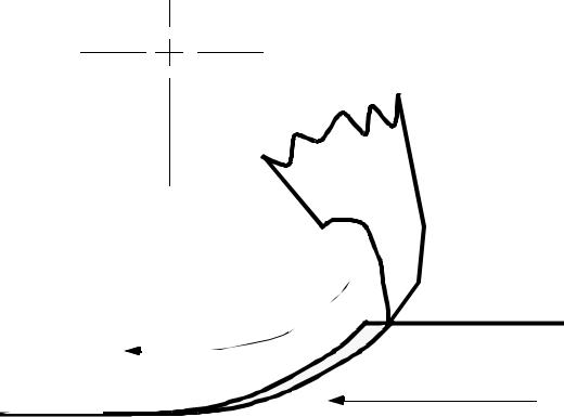
- •1. TABLE OF CONTENTS
- •2. BASIC MANUFACTURING
- •2.1 INTRODUCTION
- •2.2 PRACTICE PROBLEMS
- •3. MANUFACTURING COST ESTIMATING
- •3.1 COSTS ESTIMATES
- •3.2 COGS (COST OF GOODS SOLD)
- •3.3 VALUE ENGINEERING
- •3.4 REFERENCES
- •4. BASIC CUTTING TOOLS
- •4.1 CUTTING SPEEDS, FEEDS, TOOLS AND TIMES
- •4.2 HIGH SPEED MACHINING
- •4.3 REFERENCES
- •5. CUTTING THEORY
- •5.1 CHIP FORMATION
- •5.2 THE MECHANISM OF CUTTING
- •5.2.1 Force Calculations
- •5.2.1.1 - Force Calculations
- •5.2.1.2 - Merchant’s Force Circle With Drafting (Optional)
- •5.3 POWER CONSUMED IN CUTTING
- •5.4 PRACTICE QUESTIONS
- •5.5 TEMPERATURES IN CUTTING
- •5.6 TOOL WEAR
- •5.7 CUTTING TOOL MATERIALS
- •5.7.1 A Short List of Tool Materials
- •5.8 TOOL LIFE
- •5.8.1 The Economics of Metal Cutting
- •5.9 REFERENCES
- •5.10 PRACTICE PROBLEMS
- •6. SAWS
- •6.1 SPEEDS AND FEEDS
- •6.2 PRACTICE PROBLEMS
- •7. DRILLING
- •7.1 TYPES OF DRILL PRESSES
- •7.2 TYPICAL DRILL PRESS OPERATIONS
- •7.3 TYPICAL DRILL BITS
- •7.3.1 Reamers
- •7.3.2 Boring
- •7.3.3 Taps
- •7.4 DRILLING PROCESS PARAMETERS
- •7.4.1 The mrr For Drilling
- •7.5 PRACTICE PROBLEMS
- •8. LATHES
- •8.1 INTRODUCTION
- •8.2 OPERATIONS ON A LATHE
- •8.2.1 Machine tools
- •8.2.1.1 - Production Machines
- •8.3 LATHE TOOLBITS
- •8.3.1 Thread Cutting On A Lathe
- •8.3.2 Cutting Tapers
- •8.3.3 Turning Tapers on Lathes
- •8.4 FEEDS AND SPEEDS
- •8.4.1 The mrr for Turning
- •8.4.2 Process Planning for Turning
- •8.5 PRACTICE PROBLEMS
- •9. MILLING
- •9.1 INTRODUCTION
- •9.1.1 Types of Milling Operations
- •9.1.1.1 - Arbor Milling
- •9.1.2 Milling Cutters
- •9.1.3 Milling Cutting Mechanism
- •9.1.3.1 - Up-Cut Milling
- •9.1.3.2 - Down-Cut Milling
- •9.2 FEEDS AND SPEEDS
- •9.2.1 The mrr for Milling
- •9.2.2 Process Planning for Prismatic Parts
- •9.2.3 Indexing
- •9.3 PRACTICE PROBLEMS
- •10. GRINDING
- •10.1 OPERATIONS
- •10.2 MACHINE TYPES
- •10.2.1 Surface
- •10.2.2 Center
- •10.2.3 Centerless
- •10.2.4 Internal
- •10.3 GRINDING WHEELS
- •10.3.1 Operation Parameters
- •10.4 PRACTICE PROBLEMS
- •11. SURFACES
- •11.1 MEASURES OF ROUGHNESS
- •11.2 METHODS OF MEASURING SURFACE ROUGHNESS
- •11.2.1 Observation Methods
- •11.2.2 Stylus Equipment
- •11.2.3 Specifications on Drawings
- •11.3 OTHER SYSTEMS
- •11.4 PRACTICE PROBLEMS
- •11.4.0.1 - Roundness Testing
- •11.4.0.1.1 - Intrinsic Roundness Testing
- •11.4.0.1.2 - Extrinsic Roundness Testing
- •11.4.0.1.3 - Practice Problems
- •11.5 PRACTICE PROBLEMS
- •35. METROLOGY
- •35.1 INTRODUCTION
- •35.1.1 The Role of Metrology
- •35.2 DEFINITIONS
- •35.3 STANDARDS
- •35.3.1 Scales
- •35.3.2 Calipers
- •35.3.3 Transfer Gauges
- •35.4 INSTRUMENTS
- •35.4.1 Vernier Scales
- •35.4.2 Micrometer Scales
- •35.4.2.1 - The Principle of Magnification
- •35.4.2.2 - The Principle of Alignment
- •35.4.3 Dial Indicators
- •35.4.4 The Tool Makers Microscope
- •35.4.5 Metrology Summary
- •35.5 PRACTICE PROBLEMS
- •35.5.0.1 - Interferometry (REWORK)
- •35.5.0.1.1 - Light Waves and Interference
- •35.5.0.1.2 - Optical Flats
- •35.5.0.1.3 - Interpreting Interference Patterns
- •35.5.0.1.4 - Types of Interferometers
- •35.5.0.2 - Laser Measurements of Relative Distance
- •35.5.0.2.1 - Practice Problems
- •35.6 GAUGE BLOCKS
- •35.6.1 Manufacturing Gauge Blocks
- •35.6.2 Compensating for Temperature Variations
- •35.6.2.1 - References
- •35.6.3 Testing For Known Dimensions With Standards
- •35.6.3.1 - References
- •35.6.4 Odd Topics
- •35.6.5 Practice Problems
- •35.6.6 Limit (GO & NO GO) Gauges
- •35.6.6.1 - Basic Concepts
- •35.6.6.2 - GO & NO GO Gauges Using Gauge Blocks
- •35.6.6.3 - Taylor’s Theory for Limit Gauge Design
- •35.6.6.4.1 - Sample Problems
- •35.6.7 Sine Bars
- •35.6.7.1 - Sine Bar Limitations
- •35.6.7.1.1 - Practice Problems
- •35.6.8 Comparators
- •35.6.8.1 - Mechanical Comparators
- •35.6.8.2 - Mechanical and Optical Comparators
- •35.6.8.3 - Optical Comparators
- •35.6.8.4 - Pneumatic Comparators
- •35.6.9 Autocollimators
- •35.6.10 Level Gauges
- •35.6.10.1 - Clinometer
- •35.6.10.2 - The Brookes Level Comparator
- •35.6.11 The Angle Dekkor
- •35.7 MEASURING APARATUS
- •35.7.1 Reference Planes
- •35.7.1.1 - Granite Surface Plates
- •35.7.1.2 - Cast Iron Surface Plates
- •35.7.2 Squares
- •35.7.2.1 - Coordinate Measureing Machines
- •35.7.2.2 - Practice Problems
- •AM:35.7.3 Coordinate Measuring Machines (CMM)
- •36. ASSEMBLY
- •36.1 THE BASICS OF FITS
- •36.1.1 Clearance Fits
- •36.1.2 Transitional Fits
- •36.1.3 Interference Fits
- •36.2 C.S.A. B97-1 1963 LIMITS AND FITS(REWORK)
- •36.3 CSA MODIFIED FITS
- •36.4 CSA LIMITS AND FITS
- •36.5 THE I.S.O. SYSTEM
- •36.6 PRACTICE PROBLEMS
- •42. WELDING/SOLDERING/BRAZING
- •42.1 ADHESIVE BONDING
- •42.2 ARC WELDING
- •42.3 GAS WELDING
- •42.4 SOLDERING AND BRAZING
- •42.5 TITANIUM WELDING
- •42.5.1 Practice Problems
- •42.6 PLASTIC WELDING
- •42.7 EXPLOSIVE WELDING
- •42.7.1 Practice Problems
- •43. AESTHETIC FINISHING
- •43.1 CLEANING AND DEGREASING
- •43.2 PAINTING
- •43.2.1 Powder Coating
- •43.3 COATINGS
- •43.4 MARKING
- •43.4.1 Laser Marking
- •43.5 PRACTICE PROBLEMS
- •44. METALLURGICAL TREATMENTS
- •44.1 HEAT TREATING
- •44.2 ION NITRIDING
- •44.3 PRACTICE PROBLEMS
- •45. CASTING
- •45.1 SAND CASTING
- •45.1.1 Molds
- •45.1.2 Sands
- •45.2 SINGLE USE MOLD TECHNIQUES
- •45.2.1 Shell Mold Casting
- •45.2.2 Lost Foam Casting (Expandable Pattern)
- •45.2.3 Plaster Mold Casting
- •45.2.4 Ceramic Mold Casting
- •45.2.5 Investment Casting
- •45.3 MULTIPLE USE MOLD TECHNIQUES
- •45.3.1 Vacuum Casting
- •45.3.2 Permanent Mold Casting
- •45.3.2.1 - Slush Casting
- •45.3.2.2 - Pressure Casting
- •45.3.2.3 - Die Casting
- •45.3.3 Centrifugal Casting
- •45.3.4 Casting/Forming Combinations
- •45.3.4.1 - Squeeze Casting
- •45.3.4.2 - Semisolid Metal Forming
- •45.3.5 Single Crystal Casting
- •45.4 OTHER TOPICS
- •45.4.1 Furnaces
- •45.4.2 Inspection of Casting
- •45.5 Design of Castings
- •45.6 REFERENECES
- •45.7 PRACTICE PROBLEMS
- •46. MOLDING
- •46.1 REACTION INJECTION MOLDING (RIM)
- •46.1.1 References
- •46.2 INJECTION MOLDING
- •46.2.1 Hydraulic Pumps/Systems
- •46.2.2 Molds
- •46.2.3 Materials
- •46.2.4 Glossary
- •46.3 EXTRUSION
- •46.4 PRACTICE PROBLEMS
- •47. ROLLING AND BENDING
- •47.1 BASIC THEORY
- •47.2 SHEET ROLLING
- •47.3 SHAPE ROLLING
- •47.4 BENDING
- •48. SHEET METAL FABRICATION
- •48.1 SHEET METAL PROPERTIES
- •48.2 SHEARING
- •48.2.1 Progressive and Transfer Dies
- •48.2.2 DRAWING
- •48.3 DEEP DRAWING
- •48.4 SPINNING
- •48.5 MAGNETIC PULSE FORMING
- •48.6 HYDROFORMING
- •48.7 SUPERPLASTIC FORMING
- •48.7.1 Diffusion Bonding
- •48.8 PRACTICE PROBLEMS
- •49. FORGING (to be expanded)
- •49.1 PROCESSES
- •49.1.1 Open-Die
- •49.1.2 Impression/Closed Die
- •49.1.3 Heading
- •49.1.4 Rotary Swaging
- •50. EXTRUSION AND DRAWING
- •50.1 DIE EXTRUSION
- •50.1.1 Hot Extrusion
- •50.1.2 Cold Extrusion
- •50.2 HYDROSTATIC EXTRUSION
- •50.3 DRAWING
- •50.4 EQUIPMENT
- •50.5 PRACTICE PROBLEMS
- •51. ELECTROFORMING
- •51.1 PRACTICE PROBLEMS
- •52. COMPOSITE MANUFACTURING
- •52.1 FIBER REINFORCED PLASTICS (FRP)
- •52.2 COMPOSITE MANUFACTURING
- •52.2.1 Manual Layup
- •52.2.2 Automated Tape Lamination
- •52.2.3 Cutting of Composites
- •52.2.4 Vacuum Bags
- •52.2.5 Autoclaves
- •52.2.6 Filament Winding
- •52.2.7 Pultrusion
- •52.2.8 Resin-Transfer Molding (RTM)
- •52.2.9 GENERAL INFORMATION
- •52.2.10 REFERENCES
- •52.2.11 PRACTICE PROBLEMS
- •53. POWDERED METALLURGY
- •53.1 PRACTICE PROBLEMS
- •54. ABRASIVE JET MACHINING (AJM)
- •54.1 REFERENCES
- •54.2 PRACTICE PROBLEMS
- •55. HIGH PRESSURE JET CUTTING
- •56. ABRASIVE WATERJET CUTTING (AWJ)
- •57. ULTRA SONIC MACHINING (USM)
- •57.1 REFERENCES
- •57.1.1 General Questions
- •58. ELECTRIC DISCHARGE MACHINING (EDM)
- •58.1 WIRE EDM
- •58.2 PRACTICE PROBLEMS
- •58.3 REFERENCES
- •59. ELECTROCHEMICAL MACHINING (ECM)
- •59.1 REFERENCES
- •59.2 PRACTICE PROBLEMS
- •60. ELECTRON BEAM MACHINING
- •60.1 REFERENCES
- •60.2 PRACTICE PROBLEMS
- •61. ION IMPLANTATION
- •61.1 THIN LAYER DEPOSITION
- •61.2 PRACTICE PROBLEMS
- •62. ELECTROSTATIC SPRAYING
- •62.1 ELECTROSTATIC ATOMIZATION METHOD
- •62.2 PRACTICE PROBLEMS
- •63. AIR-PLASMA CUTTING
- •63.1 REFERENCES
- •63.2 PRACTICE PROBLEMS
- •64. LASER CUTTING
- •64.1 LASERS
- •64.1.1 References
- •64.2 LASER CUTTING
- •64.2.1 References
- •64.3 PRACTICE PROBLEMS
- •65. RAPID PROTOTYPING
- •65.1 STL FILE FORMAT
- •65.2 STEREOLITHOGRAPHY
- •65.2.1 Supports
- •65.2.2 Processing
- •65.2.3 References
- •65.3 BONDED POWDERS
- •65.4 SELECTIVE LASER SINTERING (SLS)
- •65.5 SOLID GROUND CURING (SGC)
- •65.6 FUSED DEPOSITION MODELLING (FDM)
- •65.7 LAMINATE OBJECT MODELING (LOM)
- •65.8 DIRECT SHELL PRODUCTION CASTING (DSPC)
- •65.9 BALLISTIC PARTICLE MANUFACTURING (BPM)
- •65.9.1 Sanders Prototype
- •65.9.2 Design Controlled Automated Fabrication (DESCAF)
- •65.10 COMPARISONS
- •65.10.1 References
- •65.11 AKNOWLEDGEMENTS
- •65.12 REFERENCES
- •65.13 PRACTICE PROBLEMS
- •66. PROCESS PLANNING
- •66.1 TECHNOLOGY DRIVEN FEATURES
- •66.2 MOST SIGNIFICANT FEATURE FIRST
- •66.3 DATABASE METHODS
- •66.4 MANUFACTURING VOLUMES
- •66.5 STANDARD PARTS
- •66.6 PRACTICE PROBLEMS
- •66.6.1 Case Study Problems
- •66.6.1.1 - Case 1
- •66.7 REFERENCES
page 97
centre of cutter
rotation of cutter
table/work feed at constant rate
•When this cutter makes contact with the work, it must begin cutting at the maximum torque. As a result, a back-lash eliminator must be used to take play out of the system.
•This method has advantages,
-The cutter forces are directed into the table, which reduces fixture forces, and allows thinner workpieces
-There is less radial pressure on the arbor
-Better surface finishes obtained because there is no “dig-in”
9.2 FEEDS AND SPEEDS
• Milling is somewhat different than drilling and turning,
page 98
CS = rpm × |
C |
|
|
|
|
|
C = π-------D |
= |
-----------π D |
|
|
|
|
12 |
|
1000 |
|
|
|
|
rpm = 12------------------× |
CS |
= |
1000------------------------- |
× |
CS |
|
|
π × |
D |
|
π × |
|
D |
|
imperial |
|
|
|
metric |
|
where, |
|
|
|
|
|
|
CS = cutting speed (fpm or m/s) - can be selected from tables rpm = revolutions per minute of the machine spindle
C = circumference of the cutter (ft. or m) D = diameter of the cutter (in. or mm)
F = fpt × #t × rpm
where,
F = feed rate (in./min.) - this is independent of the spindle rpm fpt = feed per tooth - found in tables
#t = number of teeth on a particular tool
L L
T = -- = -------------------
F rpm × F
C = T × R
where,
L = length of cut (in. or mm)
R= Machine cost ($/min.)
•Typical speeds are, [Krar]
page 99
Work Material |
HSS tool |
carbide tool |
|
(fpm) |
(fpm) |
|
|
|
machine steel |
70-100 |
150-250 |
tool steel |
60-70 |
125-200 |
cast iron |
50-80 |
125-200 |
bronze |
65-120 |
200-400 |
aluminum |
500-1000 |
1000-2000 |
|
|
|
• Typical feed per tooth values for HSS cutters, [Krar] |
|
|
|
|||||
|
Material |
|
face mill |
helical |
slot/side |
end mill |
form cut |
circular |
|
|
|||||||
|
|
|
(in.) |
mill |
mill |
(in.) |
(in.) |
saws |
|
|
|
|
(in.) |
(in.) |
|
|
(in.) |
|
|
|
|
|
|
|
|
|
|
aluminum |
|
0.022 |
0.018 |
0.013 |
0.011 |
0.007 |
0.005 |
|
brass/bronze (medium) |
|
0.014 |
0.011 |
0.008 |
0.007 |
0.004 |
0.003 |
|
cast iron (medium) |
|
0.013 |
0.010 |
0.007 |
0.007 |
0.004 |
0.003 |
|
machine steel |
|
0.012 |
0.010 |
0.007 |
0.006 |
0.004 |
0.003 |
|
tool steel (medium) |
|
0.010 |
0.008 |
0.006 |
0.005 |
0.003 |
0.003 |
|
stainless steel |
|
0.006 |
0.005 |
0.004 |
0.003 |
0.002 |
0.002 |
|
|
|
|
|
|
|
|
|
• Typical feed per tooth values for cemented carbide (tipped) cutters, [Krar]
Material |
face mill |
helical |
slot/side |
end mill |
form cut |
circular |
|
(in.) |
mill |
mill |
(in.) |
(in.) |
saws |
|
|
(in.) |
(in.) |
|
|
(in.) |
|
|
|
|
|
|
|
aluminum |
0.020 |
0.016 |
0.012 |
0.010 |
0.006 |
0.005 |
brass/bronze (medium) |
0.012 |
0.010 |
0.007 |
0.006 |
0.004 |
0.003 |
cast iron (medium) |
0.016 |
0.013 |
0.010 |
0.008 |
0.005 |
0.004 |
machine steel |
0.016 |
0.013 |
0.009 |
0.008 |
0.005 |
0.004 |
tool steel (medium) |
0.014 |
0.011 |
0.008 |
0.007 |
0.004 |
0.004 |
stainless steel |
0.010 |
0.008 |
0.006 |
0.005 |
0.003 |
0.003 |
|
|
|
|
|
|
|
page 100
9.2.1 The mrr for Milling
• considering the parameters defined in the discussion of speeds and feeds, etc, the mrr is given below,
d
w
work fed into cutter |
mrr = w × d × F
where,
w = width of cut d = depth of cut
9.2.2 Process Planning for Prismatic Parts
• The basic steps are,
1.Cut off the stock slightly larger than required.
2.Cut the basic outside diameter to size using a milling machine.
3.Lay out the basic features of the parts (in manual setups, this involves coating the surface with a blue stain, this is then cut and marked).
4.Use a bandsaw to rough cut the work.
5.On the mill, cut steps, radii, angles, grooves, etc.
6.Lay out the holes to be drilled, and then drill them.
7.Ream holes as required
8.Grind any surfaces that require it. Ground surfaces should generally have 0.010”
9.2.3 Indexing
• It may sometimes become necessary to rotate parts on a milling machine, beyond the rotation
page 101
offered in some beds (e.g. Universal Milling Machine).
•Some of the applications that require this capability are milling of,
-polygons,
-splines
-gears,
-cams
-spirals
•This method can be done with a dividing head. This is basically a worm gear unit. As the crank is turned, the cylindrical gear will drive the round gear. This will result in an apparatus that takes large motions in the crank, and results in small rotations of the work. When coupled with a scale of some description this becomes very accurate.
•If a worm wheel has 40 teeth, each rotation of the crank will result in a rotation of 40/360 degrees, or 1/40th of a rotation. This means the rotation is 40:1.
****************************** INCLUDE FIGURES OF INDEXING HEAD
•There are two methods of indexing,
-Direct Indexing - A notched plate is located so that the crank shaft can be fixed at set positions (notches).
-Simple Indexing - Work is rotated by turning a crank. The crank is finally positioned using a plate with holes, and a sector arm. (The sector arm is used to count off the divisions on the plates)
•An example of the calculations involved is,
page 102
Say that we want to mill a polygon on 11 sides (i.e., 1/11th of a circle).
First, we will assume that we have a worm ratio of 40:1, and that we are using a Brown and Sharp #2 plate.
Next, we will calculate the fraction of the indexed plate to be covered,
INDEX = |
40 1 |
= |
40 |
= 3 |
7 |
----- ----- |
----- |
----- |
|||
|
1 11 |
|
11 |
|
11 |
So, we must turn the crank handle 3 times, plus a bit more. Next we must determine which ring of index holes to use, and how many to count ahead by.
We can do this by looking at the remainder (7/11) and taking the denominator (11). Next we look at the counts available for the Brown and Sharp #2 plate
(i.e., 21, 23, 27, 29, 31, 33), and from this we will notice that 33 is a multiple of 11. Therefore we can compute the number of divisions required with,
7
holes = 33 ----- = 21 11
Therefore in total, we must advance the crank 3 full rotations, and 21 holes (in the ring of 33) to rotate 1/11th of a circle.
• Another example of indexing considers a rotation of 50 degrees,
First we will calculate the total indexing required,
INDEX = |
|
40 |
|
50 |
= |
2000 |
= |
50 |
= 5 |
5 |
|
----- |
|
-------- |
----------- |
----- |
-- |
||||
|
1 |
360 |
|
360 |
|
9 |
|
9 |
Therefore there are 5 full rotations of the indexing wheel required. Next we look at the list of indexing plates. Assume we are using the Cincinnati Standards Plates, we should look for the ring that has lowest number of index holes and is a multiple of 9. This would be 54 on the other side. Therefore we would advance the sector arm by,
5
holes = 54 --9 = 30