


16-32 ELECTRICAL SYSTEM
Charging System
•Apply a thin coat of molybdenum disulfide grease to the
•shaft [A], and install it and starter idle gear [B].
Install the alternator cover (see Alternator Cover Installation).
Alternator Inspection
There are three types of alternator failures: short, open (wire burned out), or loss in rotor magnetism. A short or open in one of the coil wires will result in either a low output, or no output at all. A loss in rotor magnetism, which may be caused by dropping or hitting the alternator, by leaving it near an electromagnetic field, or just by aging, will result in low• output.
To check the alternator output voltage, do the following procedures.
○Turn off the ignition switch.
○Remove the left frame cover (see Alternator Cover Removal).
○Disconnect the alternator lead connector [A]. ○Connect the hand tester as shown in the table 1. ○Start the engine.
○Run it at the rpm given in the table 1.
○Note the voltage readings (total 3 measurements).
Table 1 Alternator Output Voltage |
|
|||||||
|
|
|
|
|
|
|
|
|
|
|
Tester |
Connections |
|
Reading |
|||
|
|
Range |
Tester (+) to |
|
Tester (–) to |
|
@ 4,000 rpm |
|
|
|
250 V AC |
One Black |
|
Another Black |
|
42 V or more |
|
|
|
|
lead |
|
lead |
|
|
|
|
|
If the output voltage shows the value in the table, the al- |
||||||
|
|
|||||||
|
|
|||||||
|
|
ternator operates properly. |
|
|
|
|
||
|
|
If the output voltage shows a much higher than the value |
||||||
|
|
|||||||
|
|
|||||||
|
|
in the table, the regulator/rectifier is damaged. A much |
||||||
|
|
lower reading than that given in the table indicates that |
||||||
|
|
the alternator is defective. |
|
|
|
|
||
•Check the stator coil resistance as follows. |
|
|||||||
|
|
Stop the engine. |
|
|
|
|
||
○Connect the hand tester as shown in the table 2. |
||||||||
○Note the readings (total 3 measurement). |
|
|||||||
○ |
|
|
|
|
|
|
||
Table 2 Stator Coil Resistance |
|
|
|
|
||||
|
|
|
|
|
|
|||
|
|
Tester |
Connections |
|
Reading |
|||
|
|
Range |
Tester (+) to |
|
Tester (–) to |
|
|
|
|
|
|
|
|
||||
|
|
× 1 Ω |
One Black |
|
Another Black |
|
|
0.3 0.4 Ω |
|
|
lead |
|
lead |
|
|
||
|
|
|
|
|
|
|||
ELECTRICAL SYSTEM 16-33
Charging System
If there is more resistance than shown in the table, or no hand tester reading (infinity) for any two leads, the stator has an open lead and must be replaced. Much less than this resistance means the stator is shorted, and must be
•replaced.
Using the highest resistance range of the hand tester, measure the resistance between each of the black leads and chassis ground.
Any hand tester reading less than infinity (∞) indicates a short, necessitating stator replacement.
If the stator coils have normal resistance, but the voltage check showed the alternator to be defective; then the rotor magnets have probably weakened, and the rotor must be replaced.
Special Tool - Hand Tester: 57001–1394
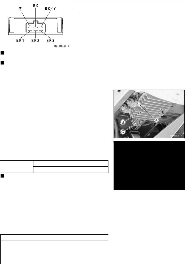
Regulator/Rectifier• Inspection
Remove:
Bolts [A]
Regulator/Rectifier [B]
Connector [C] (disconnect)
Rectifier• Circuit Check:
Check conductivity of the following pair of terminals.
Rectifier Circuit Inspection
Tester connection W-BK1, W–BK2, W–BK3 BK/Y-BK1, BK/Y-BK2, BK/Y-BK3
The resistance should be low in one direction and more than ten times as much in the other direction. If any two leads are low or high in both directions, the rectifier is defective and must be replaced.
NOTE
○The actual meter reading varies with the meter used and the individual rectifier, but, generally speaking the lower reading should be from zero to one half the scale.
Regulator Circuit Check:
To test the regulator out of circuit, use three 12 V batteries and a test light (12 V 3 6 W bulb in a socket with leads).
CAUTION
The test light works as an indicator and also a current limiter to protect the regulator/rectifier from excessive current. Do not use an ammeter instead of a test light.
•Checktinuing.to be sure the rectifier circuit is normal before con-

16-34 ELECTRICAL SYSTEM
Charging System
•Do the 1st step regulator circuit test:
○Connect the test light and the 12 V battery to the regulator/rectifier as shown.
○Check BK1, BK2, and BK3 terminal respectively.
If the test light turns on, the regulator/rectifier is defective. Replace it.
 If the test light does not turn on, continue the test.
•Do the 2nd step regulator circuit test:
○Connect the test light and the 12 V battery in the same manner as specified in the "Regulator Circuit Test–1st Step".
○Apply 12 V to the voltage BR terminal.
○Check BK1, BK2, and BK3 terminal respectively.
If the test light turns on, the regulator/rectifier is defective. Replace it.
 If the test light does not turn on, continue the test.
•Do the 3rd step regulator circuit test:
○Connect the test light and the 12 V battery in the same manner as specified in the "Regulator Circuit Test–1st Step".
○Momentarily apply 24 V to the voltage BR terminal by adding a 12 V battery.
○Check BK1, BK2, and BK3 terminals respectively.
CAUTION
Do not apply more than 24 volts. If more than 24 volts is applied, the regulator/rectifier may be damaged. Do not apply 24 V more than a few seconds. If 24 volts is applied for more than a few seconds, the regulator/rectifier may be damaged.
If the test light did not light when the 24 V was applied momentarily to the voltage monitoring terminal, the regulator/rectifier is defective. Replace it.
If the regulator/rectifier passes all of the tests described, it may still be defective. If the charging system still does not work properly after checking all of the components and the battery, test the regulator/rectifier by replacing it with a known good unit.

ELECTRICAL SYSTEM 16-35
Charging System
Charging• Voltage Inspection
•Check the battery condition (see Battery section). Warm up the engine to obtain actual alternator operating
•conditions.
•Remove the seats (see Frame chapter).
Check that the ignition switch is turned off, and connect the hand tester [A] to the battery terminals [B].
Special Tool - Hand Tester: 57001–1394 [A]
•Start the engine, and note the voltage readings at various engine speeds with the headlight turned on and then turned off. (To turn off the headlight, disconnect the headlight connector on the headlight unit.) The readings should show nearly battery voltage when the engine speed is low, and, as the engine speed rises, the readings should also rise. But they must be kept under the specified voltage.
Charging Voltage
|
|
|
|
|
|
|
|
Tester |
Connections |
Reading |
|
|
|
Range |
Tester (+) to |
Tester (–) to |
|
|
|
|
|||
|
|
25 V DC |
Battery (+) |
Battery (–) |
14.2 15.2 V |
•Turn off the |
ignition switch to stop the engine, and discon- |
||||
|
|
nect the hand tester. |
|
|
|
|
|
If the charging voltage is kept between the values given in |
|||
|
|
||||
|
|
the table, the charging system is considered to be working |
|||
|
|
normally. |
|
|
|
|
|
If the charging voltage is much higher than the values |
|||
|
|
||||
|
|
specified in the table, the regulator/rectifier is defective |
|||
or the regulator/rectifier leads are loose or open.
If the charging voltage does not rise as the engine speed increases, then the regulator/rectifier is defective or the alternator output is insufficient for the loads. Check the alternator and regulator/rectifier to determine which part is defective.