

Учебное пособие 2132
.pdfRussian Journal of Building Construction and Architecture
E,
MPa
V, l
Fig. 5. Graphs of the acquired material strength of the base and subgrade on the volume of therepairing solution for different viscosityvalues:
1 in the sand layer at a high viscositylevel; 2 in the sand layer at an optimal viscositylevel; 3 in the sand layer at a reduced viscositylevel; 4 in the subgrade at a high viscositylevel;
5 in the subgrade base at a medium viscositylevel; 6 in the subgrade base at an optimal viscositylevel
Conclusions. The mathematical analysis that we performed showed that the use of the method of injecting liquid solutions into the base course layer for reinforcement purposes is advantageous. A smaller mechanical impact on the road structure layers, formation of the areas with smaller water permeability to that enable the processes associated with water and subbase mineral particle migration to stop. In order to achieve a standard strength of a structure in the reinforcement, it is necessary to use solutions with optimal viscosity levels, each for its layer. A 15 % decrease in the viscosity of the solution leads to a two-fold increase in the consumption. By controlling the viscosity properties of the solution, the permeability area in the layer can be controlled as well.
Operation of a road structure is closely associated with monitoring it and subsequent repairs and maintenance. Mathematical modeling showed that the more bendings caused by changes in the physical and mechanical properties due to moisturizing there are in a defect area, the greater viscosity is required for injection of liquid solutions in the subbase layers. This reinforces each of the subbase layers with solutions with the characteristics similar to those of a layer restoring them to their original state. Possible additives binding moisture in the subbase accelerate the restoration of the load-carrying properties. The methods of alternating solutions forming layers with different physical and mechanical properties might be suggested to be used for further rehabilitation of a pavement.
60
Issue № 2 (42), 2019 |
ISSN 2542-0526 |
References
1.Babaskin Yu. G. Ukreplenie gruntov in"ektirovaniem pri remonte avtomobil'nykh dorog [Strengthening the soil byinjection in the repair of roads]. Minsk, UP “Tekhnoprint” Publ., 2002. 176 p.
2.Bezruk V. M. Ukreplenie gruntov [Strengthening of soil]. Moscow, Transport Publ., 1982. 231 p.
3.Golovanov A. M., Pashkov V. I., Revo G. A. [Experience of consolidation of subsidence and bulk soils of the bases of the bases of the bases of buildings and constructions by cementation]. Sbornik nauchnykh trudov [Collection of proceedings]. Rostov-on-don, 2004, pp. 68—71.
4.Kambefor A. In"ektsiya gruntov: printsipy i metody [Soil injection: principles and methods]. Moscow, Energiya Publ., 1971. 333 p.
5.Lanis A. L. Sposobyusileniya zemlyanogo polotna in"ektirovaniem [Ways to strengthen the roadbed byinjection]. Izvestiya Transsiba, 2016, no. 3 (27), pp. 117—124.
6.Rudenskii A. V. Dorozhnye asfal'tobetonnye pokrytiya [Road asphalt concrete pavement]. Moscow, Transport Publ., 1992. 253 p.
7.Erlingsson S., Rahman M. S. Evaluation of Permanent Deformation Characteristics of Unbound Granular Materials from Multi-Stage Repeated Load Triaxial Test. Transportation Research Record, 2013, no. 2369, pp. 11—12.
8.Fontes L. P. T. L., Trichês G., Pais J. C., Pereira P. A. A. Evaluating permanent deformation in asphalt rubber mixtures. J. Constr. Build. Mater, 2010, vol. 24, pp. 1193—1200.
9.Francken L., Clauwaert C. Characterization and structural assessment of bound materials for flexible road structures. Proc. of the 6th International Conference on Asphalt Pavements. Ann Arbor, Michigan, 1987, pp. 130—144.
10.Jaritngam S. Method of reducing soil movements for deep excavations in soft clay: M. Thesis. Nanyang Technological University, Singapore, 1996.
11.Nakamura Ts. Limit Analysis of Non-symmetric Sandwich Shells. IASS Symposium on Non-Classical Shell Problems, Sept. 2—5, 1963. Warszawa, 1964, pp. 768—784.
12.Pérez I., Medina L., Romana M. G. Permanent deformation models for a granular material used in road pavements. Constr. Build. Mater, 2006, no. 20, pp. 790—800.
13.Sweere G. T. H. Unbound granular bases for roads: PhD Thesis. Universityof Delft, Holland, 1990. 429 р.
14.Theyse H. L. Mechanistic-empirical modelling of thepermanent deformation of unbound pavement layers. Proceedings of the Eighth International Conference on the Structural Design of Asphalt Pavements. Seattle, Universityof Washington, 1997, pp. 1579—1594.
15.Słowikowski D., Kacprzak G. Implementation of low pressure injection for soil reinforcement and sealing — selected application. Technical transactions environment engineering, 2013, no. 1—S, pp. 111—119.
16.Xu Q., Chen H., Prozzi J. A. Performance of fiber reinforced asphalt concreteunder environmental temperature and water effects. J. Constr Build Mater, 2010, vol. 24, no. 10, pp. 2003—2010.
17.Walubita L. F. Preliminary Fatigue Analysis of a common TxDOT Hot mix Asphalt Concrete Mixture. Report № FHWA/TX-05/0-4468-1. Texas Transportation Institute, 2004. 117 p.
18.Winterkorn H. F., Pamukcu S. Soil Stabilization and Grouting. Foundation Engineering Handbook. N.-Y., Van Nostrend Reindhold, 1991, pp. 317—378.
61

Russian Journal of Building Construction and Architecture
BUILDING MECHANICS
DOI 10.25987/VSTU.2019.42.2.007
UDC 624.04
M. N. Kirsanov1
CALCULATION OF G-SHAPED FARMING OF ROAD SIGNS AND EQUIPMENT
National Research University «Moscow Power Engineering University»
Russia, Moscow, tel.: (495)362-73-14, e-mail: c216@Ya.ru
1D. Sc. in Physics and Mathematics, Prof. of the Dept. of Robotics, Mechatronics,
Dynamics and Strength of Machinery
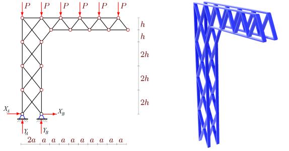
Statement of the problem. A possible scheme of a flat externally statically indeterminate hingebar construction with a console is considered. Rack and console trusses have a periodic structure. The analytical dependence of the truss deformations under various loads on the number of panels in the vertical rack and in the console is deduced.
Results. For the three types of loads, the analytical dependencies of the truss on the number of panels, sizes and loads were found using the Maxwell — Mohr formula. The solution has a polynomial form in the number of panels. When generalizing particular solutions to an arbitrary number of panels, the inductive method and the operators of the Maple computational mathematics system were applied. The distribution of forces in the truss bars and analytical expressions for support reactions are found. Asymptotic properties of the solutions are found.
Conclusions. The proposed scheme of a console with a cruciform lattice in the supporting part allows an exact solution of the problem of deflection with arbitraryproportions of the structure to be identified. The resulting formulas are compact and allow us to estimate the rigidity, strength and stabilityof the structure.
Keywords: console truss, deflection, double induction, external static indetermination, analytical solution.
Introduction. One ofthe optionsof installing road signing, marking and different types ofelectric (lighting) and electronics (information, control) uses L-mounts in road shoulders [7, 8, 13]. This solution is commonly used when road width does not allow for a support over all carriageways. A mount can be designed as a truss. Its possible deformations are crucial to calculate, even more so than strength particularly if reading or recording devices are being mounted.
© Kirsanov M. N., 2019
62
Issue № 2 (42), 2019 |
ISSN 2542-0526 |
The objective of the paper is to identify analytical dependencies of deformations of a structure (Fig. 1) on its size, loads and number of panels in the vertical part (tie) and the horizontal one (flange). Similar problems for beam [1, 9, 20], arch [5, 21] and grid [3, 15, 16] truss have beed addressed using a computational mathematics system and the induction method. Here it gets more complicated as there are two independent numerical parameters each of which is of importance in truss deformation and external static indeterminateness of a structure with two motionless hinge bearings.
Besides size and load, the major parameters of the task are the number m of panels in the tie and n panels in the flange. The solution of the problem requires a more complex double induction for generalizing particular solutions for a general case and identifying a quite universal formula suitable for high mounts with a small console lifting as well as large consoles with a low support. In practise these are dual truss s (Fig. 2) with horizontal bonds.
Fig. 1. Truss, n = 5, m = 4. |
Fig. 2. Truss as part of a space structure. |
Load distributed along the console and support reactions |
Horizontal bonds are not depicted n = 5, m = 4 |
1. Structure. The flat girdle model under discussion (Fig. 1) has 2(n + m) + 1 hinges and s = 4(n + m) + 2 bars. Obviously, the firder is statistically determined, the bars are assumed to be elastic and the hinges ideal. Two motionless hinge bearings make the structure appear to be statically indeterminate. For such tasks involving inequilibrium equations the entire truss does not suffice in order to identify four support reactions. Vertical components of support reactions can be identified using the equilibrium condition of the system but horizontal ones cannot be. In order to identify those, either a universal principle of possible shifts is needed ot the
63
Russian Journal of Building Construction and Architecture
equilibrium of all the truss nodes should be calculated while identifying the conditions in all the bars inclusing four supports. This is what we intend to do below. For that, it is more suitable to use a well-established computing software in the computational mathematics system called
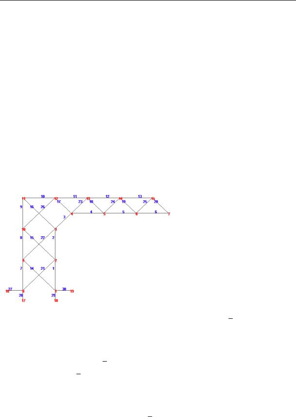
Maple [4]. This sytem produces analytical expressions of efforts necessary for using the Max- well-Mohr formula and obtaining formula solutions. The software employs the methods of sections. The bars and nodes are numbered (Fig. 3). In the cycle along the truss bars a matrix of equilibrium equations is filled that consists of force direction cosines. These values (in the analytical form as well) are determined using the coordinatesofthe nodes in the structure.
The start of the coordinates is chosen in the left hinge support. The coordinates are introduced into the cycles with the length specified by the parameters:
xi 2a, yi yi m n |
2h(i 1), xi m n, i 1,..,m, |
|
xi m a(2i 1), yi m h(2m 1), |
i 1,...,n, |
|
xi n 2m 2a(i 1), |
yi n 2m 2mh, |
1,...,n 1. |
Fig. 3. Numbers of the bars and nodes,
n = 4, m = 3
The structure of the truss grid is formed using the auxuliairy vectors Vi , i 1,...,s with the components, i.e. numbers of the ends of corresponding bars. The side bars of the tie and flange girth are specified by e.g., the vectors:
Vi [i,i 1], i 1,...,n m 1,
Vi n m 1 [i n m,i n m 1], i 1,...,n m.
2. Solution. The equilibrium equation system in the projections onto the coordinate axis is written into the matrix G along with the force direction cosines in the bars that are calculated using the node coordinates and suited to the vectors Vi , i 1,...,s . In odd lines the matrices there are force direction cosines with a horizontal axis x, those with the axis y in the even ones. For even loading of the flange nodes the right part of the equation system containing loads in the even
64

Issue № 2 (42), 2019 |
ISSN 2542-0526 |
lines takes the form of the vector B2i P, i 2m n 1,..,2(n m) 1. The remaining com-
ponentsofthe vector are zero.
A truss bend (a vertical shift of the hinge n + 1 of the lower girth) are given by the Maxwell Mohr formula:
s 4 |
N nl |
|
|
|
i i i |
, |
(1) |
EF |
|||
i 1 |
i |
|
|
where Ni are the forces in the i-th truss bar inflicted by the load; ni is the force in the same bar caused by a single vertical force; li is the length of the bar; EFi is the rigidity of the bars. The sum does not include four rigid support bars. The rigidity of all the bars except the vertical tie is assumed to be EF, the rigidity of the ties is EFγ where γ > 1.
The forces ni are determined using the equation system with the right-hand part B2i 1,
i m n.
Solving the bend task analytically for trusses with a varying number of panels we get that ultimately the bend expression is identical:
|
|
|
A |
a3 C |
n,m |
c3 |
H |
n,m |
h3 |
/ |
|
||
|
|
EF P |
n,m |
|
|
|
|
|
, |
(2) |
|||
|
|
|
EFh2 |
|
|
|
|||||||
|
|
|
|
|
|
|
|
|
|
|
|||
where c |
|
|
|
|
|
|
|
|
|||||
a2 h2 |
. The coefficients are as follows: |
|
|
|
|
|
|
|
|||||
|
|
A |
2n2(n2 3n 3), |
|
|
|
|
|
|
||||
|
|
n,1 |
|
|
|
|
|
|
|
|
|
|
|
|
|
C |
2n3 (13/2)n2 8n 1/2, |
(3) |
|||||||||
|
|
n,1 |
|
|
|
|
|
|
|
|
|
|
|
|
|
Hn,1 |
2n 2. |
|
|
|
|
|
|
|
|
||
The dependencies of the coefficients on the number of panels were obtained as those of recurrent equations using the operators rgf_findrecur and rsolve of the Maple system. In order to identify the coefficient An,1 using the calculation data of ten truss s the operator rgf_findrecur yields a fifth-order linear recurrent equation that is met by the members of the sequence of the coefficient at a3:
An,1 5An 1.1 10An 2.1 10An 3.1 5An 4.1 An 5.1.
The solution of the equation yields the dependence for An,1 (3) at m = 1. The equation for the coefficient Cn,1 is of a lower order:
Cn,1 4Cn 1.1 6Cn 2.1 4Cn 3.1 Cn 4.1. |
(4) |
The coefficient Hn,1 appeared to be too simple and the operators of the Maple did not have to be employed for obtaining it. In order to generalize the solution for the parameter m as well, the solution for m = 2, 3, 4…. should be replicated. At m = 2 we have
65

Russian Journal of Building Construction and Architecture
An,2 2n2(n2 3n 3),
Cn,2 4n3 (31/2)n2 17n 1/ 2,
Hn,2 4n3 12n2 14n 2.
Here for the coefficient Hn,2 a fourth-order recurrent equation as in (4) was obtained. At m = 3 from the solution of the same recurrent ratios but with other initial data we get
An,3 2n2(n2 3n 3),
Cn,3 6n3 (49/ 2)n2 26n 1/ 2,
Hn,3 8n3 18n2 18n.
In order to obtain sequences with a necessary length the output should be performed at m = 1, 2, 3, …, 10. The coefficient An,m does not seem to depend on m. In order to obtain the dependence Cn,m and Hn,m on m, their coefficients should be generalized at different degrees n.
The sequence of the coefficients c |
in Cn,m at n2 is c |
= 13/2, 31/2, 49/2, 67/2, 85/2, 103/2… . |
m |
m |
|
The recurrent equation for this |
sequence is yielded by the operator rgf_findrecur |
|
cm 2cm 1 cm 2 . The solution of the equation is cm (18m 5)/2.
The remaining coefficients are found identically. As a result, we get the following final original expressions:
An,m 2n2(n2 3n 3),
Cn,m 2mn3 (18m 5)n2 /2 (9m 1)n 1/2,
Hn,m 4(m 1)n3 3(( 1)m 6m 5)n2 /2 2n(( 1)m 4m 2) 3(( 1)m 1)/2 m.
Along with (2) the dependencies for even load along the upper girdle of the console yield the solution. Simultaneously with the solution for bending in the same cycles based on the number of panels using the induction method the expressions for support reactions can also be obtained (Fig. 1). As was previously rightfully assumed, the vertical reactions do not depend on the number of panels m:
YA P(n 1)(n 2)/2, YB Pn(n 1)/2.
The horizontal reactions are equal in the modulus and their direction depends on whether m is
even or not:
XA XB ( 1)m n(n 3)/ 2. |
(5) |
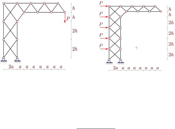
3. Other loads. The described algorithm of searching for an analytical solution has the same advantage as it is easily adjusted to another load [14]. All it takes is to make changes to the right-hand part Bj , j 1,...,s of the system of linear equations. When a console is loaded with
66
Issue № 2 (42), 2019 |
ISSN 2542-0526 |
a vertical force (Fig. 4), the formulas for the coefficients in (2) turn out more simple. Omitting the computation, we write
An,m 2n(8n2 18n 13)/3,
Cn,m 4mn2 4n(3m 1)n 9m 2,
Hn,m 8(m 1)n2 2n(( 1)m 5 6m) 5 10m 3( 1)m.
The side horizontal load (Fig. 5) also causes a vertical bend ofthe console.
Fig. 4. Truss, load at the end of the console, |
Fig. 5. Horizontal load |
n = 4, m = 3
The formula for the bend in this case takes a slightly different form also obtained ny means of the induction method
EF PCn,mc3 Hn,mh3 / , EFah
where
Cn,m (2(3 2m ( 1)m )n 1 6m 3( 1)m )/4,
Hn,m (n(4m3 6m2 3( 1)m 4m 3) 3 3( 1)m 6m)/6.
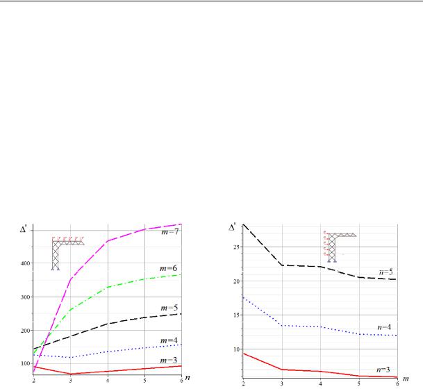
4. Analysis. Let us look at some examples of using the obtained formulas. Let the length of the console and height of the tie be fixed and the rigidity of all the bars be identical 1. The size of the panel is a L/(2n 2) and h h0 /(2m) depend on n and m. Let us also have a fixed load on the upper girdleP0 P(n 1) and introduce a dimensionless parameter of bending ' EF /(PL0 ). The character of changes in the bending on the number of the panels n largely depend on the number m (Fig. 6, L 10 m, h0 4 m).
67
Russian Journal of Building Construction and Architecture
The Maple operators allow us to evaluate the asymptomatics of the solution
lim '/n2 h0(3m 2)/(mL).
n
Fig. 7 reflects the dependence of a vertical bending of the console under a horizontal load depending on the number of panels along the vertical part of a structure. The same assumptions are made on the stability of the length of the console and the height of the tie. The only difference lies in the expression of the total load P0 = Pm. The sizes L = 5 m, h0 = 8 m are taken and the same rigidity of the bars γ = 1. Despite being mostly monotonous, the curved lines have slant asymptotes. The bending angle is negative:
lim '/m L(2n 3)/(4(n 1)2h0).
m
Fig. 6. Vertical load along the upper girdle Fig. 7. Horizontal load
Apart from the analytical solution, Maple graphic tools give insight into the force distribution in the truss bars. Fig. 8 shows the length of the bars that is proportionate to the relative force
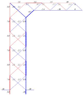
Si/P. The compressed bars are in yellow and the stretched ones in red. The figure illustrates loading in the console (see Fig. 1) at a/h 2/5, 1. It is worth noting that the most compressed and stretched bars are not in the foundation of the tie but in its second level. Further along the height forces alternate in their value and in the grid in their sign. This alternation is typical of cross-shaped grids and meets the sign alternation of reactions (5). This same truss indicates how there is nothing of the sort in the console with a regular triangular grid. A similar figure for loading the end of the flange (Fig. 4) displays no qualitative differences.
Reviews of some works employed the above method of induction as final dependencies of the bending of the truss on the number of panels are identified by means of the Maple system are
68
Issue № 2 (42), 2019 |
ISSN 2542-0526 |
presented in [5, 6]. General issues associated with analyzing regular trusses were first raised in [11, 12]. The formulas of the dependencies of the bending of regular trusses on the number of panels and their general research methods are introduced by V. A. Ignatiev [2]. The dynamics of the oscillations of mounts used for installing road signing and marking from wind gusts and transport flow considering damage inflicted by numerical methods was investigated in [7, 8, 13].
Conclusions. For L mounts a hinge statically determinate scheme was chosen for a structure with a cross-shaped grid of a tie. Despite an external statically indeterminate truss [2, 6], using the induction method for supporting the operators of the computational mathematics system Maple, a compact analytical dependence of a bending on the numbers of panels and truss sizes for three types of loads was obtained.
Fig. 8. Forces in the bars under a distributed load
on the flange, n = 4, m = 6
All the formulas have a polynomial in the number of panels and can be employhed by designing engineers as evaluation and testing tools for calculations obtained in the known software environments using a variety of numerical methods [10, 13, 19]. The most effective are the dependencies for a larger number of panels when numerical methods require a great deal of calculations and are likely to have some approximation errors.
The analysis of the solution found some features of the structure that would enable optimization of a designed structure.
69