

AVR204: BCD Arithmetics
Features
•Conversion 16 Bits ↔ 5 Digits, 8 Bits ↔ 2 Digits
•2-digit Addition and Subtraction
•Superb Speed and Code Density
•Runable Example Program
Introduction
This application note lists routines for BCD arithmetics. A listing of all implementations with key performance specifications is given in Table 1.
Table 1. Performance Figures Summary
|
Code Size |
Execution Time |
Application |
(Words) |
(Cycles) |
|
|
|
16-bit Binary to 5-digit BCD Conversion |
25 |
760 |
|
|
|
8-bit Binary to 2-digit BCD Conversion |
6 |
28 |
|
|
|
5-digit BCD to 16-bit Binary Conversion |
30 |
108 |
|
|
|
2-digit BCD to 8-bit Binary Conversion |
4 |
26 |
|
|
|
2-digit Packed BCD Addition |
19 |
19 |
|
|
|
2-digit Packed BCD Subtraction |
13 |
15 |
|
|
|
16-bit Binary to 5-digit BCD Conversion – “bin2BCD16”
This subroutine converts a 16-bit binary value to a 5-digit packed BCD number. The implementation is Code Size optimized. This implementation uses the Z-pointer's auto-decrement facility, and can not be used as is for the AT90Sxx0x series. To use this routine on an AT90Sxx0x, add an “INC ZL” instruction where indicated in the file listing.
8-bit |
Microcontroller |
Application |
Note |
Rev. 0938B–AVR–01/03 |
1 |

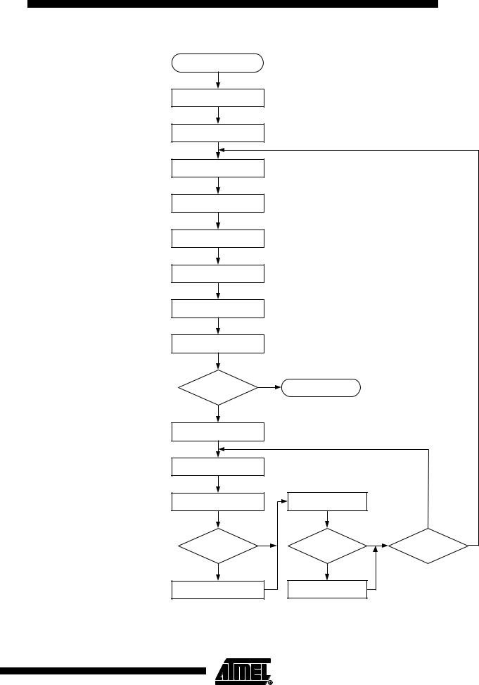
Algorithm Description
“bin2BCD16” implements the following algorithm:
1.Load Loop counter with 16.
2.Clear all three bytes of result.
3.Shift left input value Low byte.
4.Shift left carry into input value High byte.
5.Shift left carry into result byte 0 (two least significant digits).
6.Shift left carry into result byte 1.
7.Shift left carry into result byte 2 (most significant digit).
8.Decrement Loop counter
9.If Loop counter is zero, return from subroutine.
10.Add $03 to result byte 2.
11.If bit 3 is zero after addition, restore old value of byte 2.
12.Add $30 to result byte 2.
13.If bit 7 is zero after addition, restore old value of byte 2.
14.Add $03 to result byte 1.
15.If bit 3 is zero after addition, restore old value of byte 1.
16.Add $30 to result byte 1.
17.If bit 7 is zero after addition, restore old value of byte 1.
18.Add $03 to result byte 0.
19.If bit 3 is zero after addition, restore old value of byte 0.
20.Add $30 to result byte 0.
21.If bit 7 is zero after addition, restore old value of byte 0.
22.Goto Step 3.
In the implementation. Steps 10 - 21 are carried out inside a loop, where the Z-pointer is used for successive access of all three bytes of the result. This is shown in the flow chart shown in Figure 1.
2 AVR204
0938B–AVR–01/03
AVR204
Figure 1. “bin2BCD16” Flow Chart
BIN2BCD16
LOOP COUNTER ← 16
CLEAR RESULT (3 BYTES)
SHIFT LEFT INPUT LOW BYTE |
|
|
|
|
|
SHIFT LEFT INPUT HIGH |
|
|
|
|
|
BYTE WITH CARRY |
|
|
|
|
|
SHIFT LEFT RESULT |
|
|
|
|
|
BYTE 0 WITH CARRY |
|
|
|
|
|
SHIFT LEFT RESULT |
|
|
|
|
|
BYTE 1 WITH CARRY |
|
|
|
|
|
SHIFT LEFT RESULT |
|
|
|
|
|
BYTE 2 WITH CARRY |
|
|
|
|
|
DECREMENT |
|
|
|
|
|
LOOP COUNTER |
|
|
|
|
|
LOOP |
Y |
RETURN |
|
|
|
COUNTER = 0 |
|
|
|
|
|
|
|
|
|
|
|
N |
|
|
|
|
|
Z ← ADRESS OF |
|
|
|
|
|
RESULT BYTE 2 + 1 |
|
|
|
|
|
Z ← Z 1, |
|
|
|
|
|
TMP16A ← @Z |
|
|
|
|
|
TMP16A ← TMP16A + $03 |
|
TMP16A ← TMP16A + $30 |
|
|
|
|
|
|
|
N |
|
BIT 3 OF |
N |
BIT 7 OF |
N |
Z = ADDRESS |
Y |
TMP16A SET? |
|
TMP16A SET? |
|
OF RESULT |
|
|
|
BYTE 0? |
|
||
|
|
|
|
|
Y |
Y |
@Z ← TMP16A |
@Z ← TMP16A |
3
0938B–AVR–01/03

Usage
Performance
1.Load the 16-bit register variable “fbinH:fbinL” with the 16-bit number to be converted (High byte in “fbinH”).
2.Call “bin2BCD16”.
3.The result is found in the 3-byte register variable “fBCD2:fBCD1:fBCD0” with MSD in the lower nibble of “fBCD2”.
Table 2. “bin2BCD16” Register Usage
Register |
Input |
Internal |
Output |
|
|
|
|
R13 |
|
|
“fBCD0” – BCD Digits 1 |
|
|
|
and 0 |
|
|
|
|
R14 |
|
|
“fBCD1” – BCD Digits 2 |
|
|
|
and 3 |
|
|
|
|
R15 |
|
|
“fBCD2” – BCD Digit 4 |
|
|
|
|
R16 |
“fbinL” – Binary Value Low |
|
|
|
Byte |
|
|
|
|
|
|
R17 |
“fbinH” – Binary Value |
|
|
|
High Byte |
|
|
|
|
|
|
R18 |
|
“cnt16a” – Loop Counter |
|
|
|
|
|
R19 |
|
“tmp16a” – Temporary |
|
|
|
Storage |
|
|
|
|
|
R30 |
|
ZL |
|
|
|
|
|
R31 |
|
ZH |
|
|
|
|
|
Table 3. “bin2BCD16” Performance Figures
Parameter |
Value |
|
|
|
|
Code Size (Words) |
25 |
|
|
|
|
Average Execution Time (Cycles) |
760 |
|
|
|
|
Register Usage |
• Low Registers |
:3 |
|
• High Registers |
:4 |
|
• Pointers |
:Z |
|
|
|
Interrupts Usage |
None |
|
|
|
|
Peripherals Usage |
None |
|
|
|
|
4 AVR204
0938B–AVR–01/03