

Embedded system engineering magazine 2005.01,02
.pdfUK-based software engineering consultancy |
specialising in Device-PC interfacing and |
embedded software development |
Expertise in communications technologies: |
USB, CAN, Bluetooth and Firewire |
Working with a range of operating systems |
including Microsoft Windows, Wind River Vx |
Works, Nucleus RTOS and Linux |
Phone +44 (0)20 8341 7629 |
Email enquiries@redsoftsys.com |
Website www.redsoftsys.com |
Embedded system test solutions, with a business focus.
If you need a testing solution that’s fully tailored to your specific needs and which will deliver considerable savings on your product development and support costs, you need Seven Layer.
We offer an expert, holistic approach to embedded systems testing that will deliver real and quantifiable business benefits throughout your product development lifecycle.
For more information, call |
The benefits of choosing |
|
0131 331 7777 |
Seven Layer |
|
|
||
or visit our website at |
Reduced product costs |
|
www.slayer.com |
||
Reduced time to market |
||
|
||
To discover the true value of |
Improved product quality |
|
Reduced risk |
||
test automation, download |
||
|
||
our white paper today. |
Satisfied customers |
Maximising the business value of testing™
0ERFECT
.%
!UTOMATIC0RODUCTION#ODE'ENERATIONWITH
4ARGET,INK FRO KD30!#% n
&ROM THE 3IMULINK¤ -ODELDTO THE %#5
'RAPHICALHMODELING AND OFFLINE SIMULATION
%FFICIENTC!.3) # CODE!AT THE CLICK OFOADBUTTON
#ONSISTENCY BETWEEN MODEL AND # CODE
!VOIDS IMPLEMENTATIONLERRORS
&ASTER DEVELOPMENT TIMES
4ARGET,INK SETSKNEW STANDARDSEIN /3%+ 6$8 COMPATIBLECCODE GENERATION INCLUDINGUALLIOPERATINGLSYSTEM CALLS AND INTELLIGENTLTASK COMMUNICATION
4HIS MEANS SHORTER DEVELOPMENT TIMES QUALITYE ASSURANCERANDNMORE SEAMLESS INTEGRATION
D30!#% ,TDNDN&LOOR&7ESTMINSTER7(OUSE
%RMINE "USINESS"0ARK D30!#% (UNTINGDON 0% D 89
4EL
WWW DSPACE LTD UK
<In-Depth>
ESE Magazine January 05
<<processor or ECU as part of the production software build, without simulation.
Software-in-the-Loop Testing – Production code for the controller in executed in an instruction set simulator, debugger, or within the modelling environment itself for non-real-time execution with the plant model and interaction with the user.
Processor-in-the-Loop Testing – Like soft- ware-in-the-loop it executes the production code for the controller, but real I/O via CAN or serial devices passes data between the production code executing on the processor and a plant model executing in the modelling environment. As with SIL, PIL is non-real-time.
Hardware-in-the-Loop Testing – Code generated just for the plant mode runs on a highly deterministic, real-time computer. HIL serves as more of final lab test phase before road or track tests commence.
Rapid Prototyping Comparison
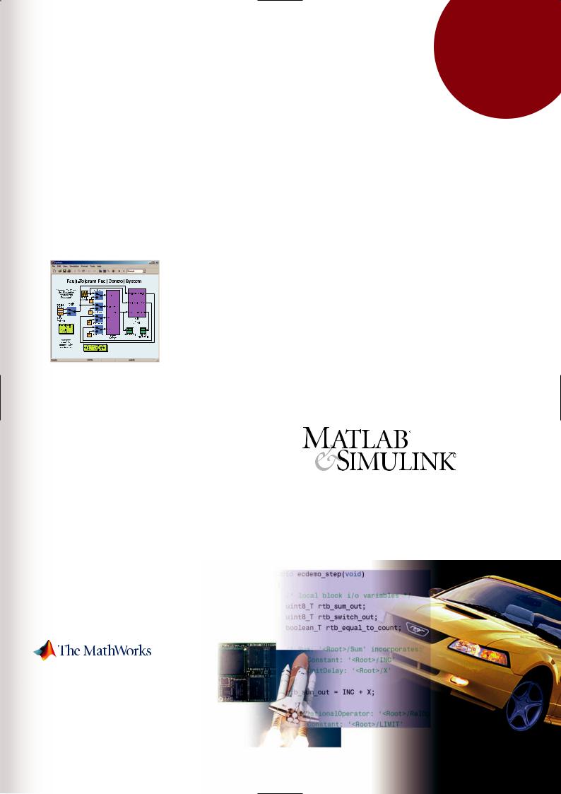
Figure 2 shows the conventional bypass and ontarget rapid prototyping approaches. Both solutions use the host machine (which runs in non- real-time), the ECU, and plant (in this case, an engine). The only major difference is that the bypass solution uses a real-time computer to run the new application and connect to the ECU (via a memory pod or network), whereas the on-tar- get solutions run directly inside the ECU.
The automotive industry has envisioned this on-target approach for years. It took code generation technology time to get there. Each approach fits a specific need.
On-target rapid prototyping blurs the distinction between conventional rapid-prototyping and production code generation and offers a refinement of the rapid prototyping code, allowing it to
Figure 2: Configurations for bypass (top) and on-target (bottom) rapid prototyping.
be easily taken into the final production build.
Getting on Target
An on-target rapid prototyping solution can be either built or one of the growing number of commercial offerings bought. The hardware is either the actual product ECU or an enhanced version of it. The software consists of target blocksets in Simulink, representing peripheral devices and operating systems tasks and resources.
Before building an embedded target, consider if it would be easier to just use the existing build environment and interface directly to the automatically generated code. This approach, sometimes termed algorithm export, is easy to do with code generators that allow a model, or subsystem within the model, to be specified as reusable. The code generated would then have the appropriate entry points and function-call signatures that interface with the existing scheduler and build process. However, if the application requires greater flexibility or is already modelled, it probably is worth the effort to develop an embedded target blockset.
Building a Baseline
Embedded Target
The fundamental requirement for an embedded target is to generate a real-time executable from a model or subsystem. Over time other capabilities can be included. A good first step might just build a baseline target, generating code and using an existing tool chain (compiler/linker/debugger) to automate the build and download.
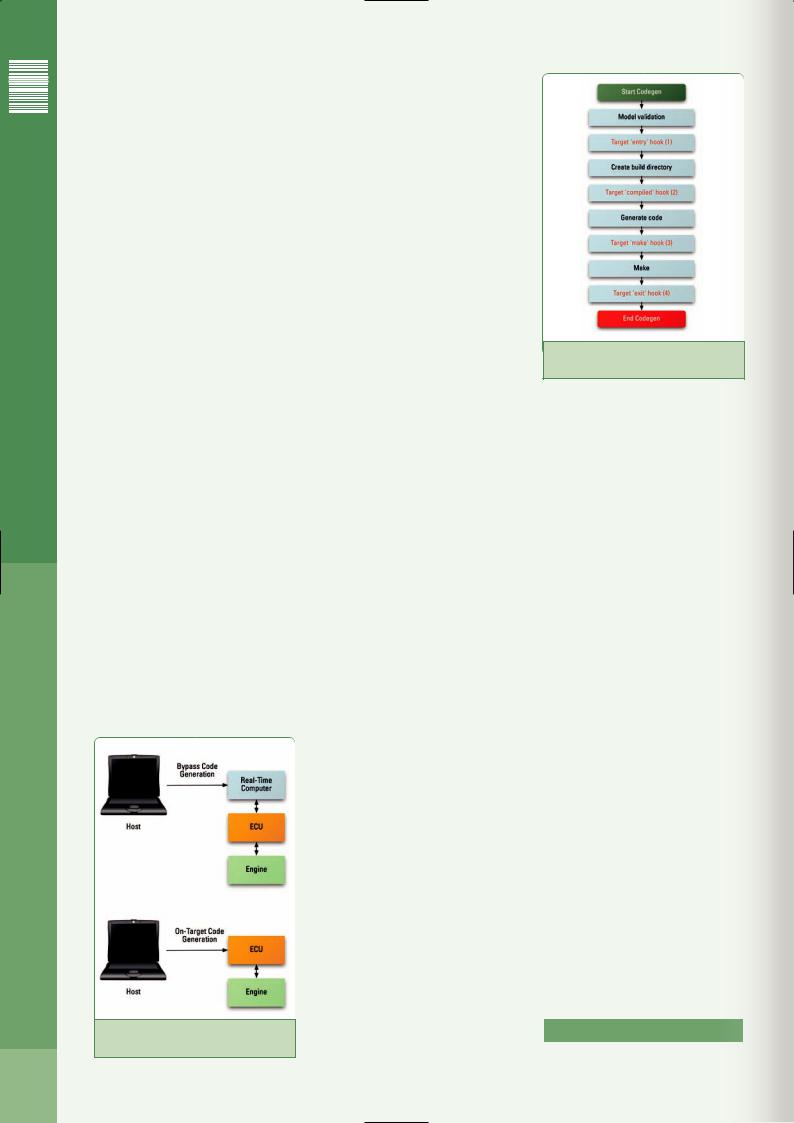
The approach for developing a baseline target depends on the modelling environment chosen. The MathWorks Real-Time Workshop Embedded Coder in Figure 3, shows the code generation process and the entry hooks into the process where the model developer is able to interact and control the target code environment.
One of the first steps is to compile the model into an in-memory representation. The target “entry” or target “compiled” hooks to add certain consistency checks, such as confirming that only integer code is used for fixed-point microcontrollers or DSPs and that only discrete time blocks are used, ensuring that the model is suitable for deployment on the target.
The next step is often the actual outputting of the C code. Here the target “make” hook can be used to ensure that data is placed into the proper memory segments and that an appropriate main program was created, with single or multitasking scheduling capabilities. Template-driven technology might be available for accomplishing these tasks. this is a good place to invoke source code analysis or lint tools to verify that the code satisfies in-house code standards.
Finally, after the code is generated and the make process concludes, the target “exit” hook
Figure 3: Entry hooks into an example code generation process.
can invoke an automatic download utility to deploy the executable onto the target. Typically, this is done with a debugger utility and if the debugger supports command script files, this can be straightforward. Another option is to invoke the instruction set simulator (ISS) and execute the code purely on the host. Executing the code in an ISS and comparing the results with the model that is simulating inside the modelling environment facilitates host/target verification efforts.
Building an Advanced Embedded Target
A more powerful embedded target would not only deploy code generated from a model onto a baseline production processor, but it also would ensure that the target executable can interact with the world outside the debugger.
Desirable features for a turnkey production target include:
●I/O driver and peripheral device support
●Code generation and targeting options for algorithm export, instruction set simulation, processor-in-the-loop simulation, or download to target
●User-controlled placement of individual variables in Flash, RAM, or other special memory sections
●Support for target interaction and parameter tuning
The effort required to build a full-featured target is considerable, so it is worth checking to see if documentation is available to serve as a guide or if a suitable target is already available off-the-shelf. <Ends>
www.mathworks.com
In-depth continues on page 48 >>
42
NEW
REAL-TIME
WORKSHOP
EMBEDDED
CODER 4
Visit www.mathworks.co.uk or call 01223 423200
Visit our web site for information on training courses online, on-site and at public locations around the world.
All trademarks are property of their respective owners.
© 2004 The MathWorks, Inc.
<Feature>
ESE Magazine January 05
Developing Effective, Reliable
Aerospace Equipment:
The Data Management Challenge
<Written by> Steven T. Graves, McObject LLC </W>
The torrent of data in aerospace applications presents a range of problems. How best can the data be managed?
MODERN COCKPITS bombard pilots with tremendous volumes of data, including tactical information, navigation data, system status, etc.
Computerized systems are used extensively to process, prioritize, and present critical data. Necessarily, on-board systems have evolved into substantial computing platforms that are tightly integrated and continuously share information, both internally and with ground-based sources. This torrent of data within aerospace embedded systems presents multifaceted data management requirements, including high performance, concurrent access, high availability, complex searching, and reliability.
One class of commercial, off-the-shelf (COTS) software plays a growing role in helping Military-Aerospace (MilAero) developers meet these challenges: real-time in-memory databases with high availability (HA) capability. While coding custom data management used to be—- and for many developers, still is—-the industry norm, many firms have found that the performance, reliability and time-to-market benefits of proven databases often justify their cost.
Technological advances have made the use of “real” databases an option in embedded MilAero systems. An in-memory embedded database operates near the speed of RAM access, and eliminates the unpredictable latency accompanying file I/O and inter-process communication. In addition, with "eager, 2-safe" replication implemented via a time-cognizant protocol, in-memory data management offers the unsurpassed reliability of a high availability system with complete redundancy and failover capability, which can be further enhanced by the use of non-volatile RAM (NVRAM).
Performance
The performance requirements and harsh operating environment of airborne systems dictate the use of embedded database systems that operate entirely in memory. The vibrations and high-gee conditions largely disqualify the use of
conventional disks due to likely mechanical dis- |
base system will outperform disk-based databas- |
ruption. Some might ask, “Why not deploy a tra- |
es in a RAM-disk by an order of magnitude or |
ditional disk-based database entirely in RAM, to |
more, and will require much less memory to store |
eliminate the hard disk’s role?” The answer is |
the same amount of data – 15% to 35% over- |
that while RAM-disk deployment speeds up tra- |
head is typical for an in-memory database versus |
ditional databases’ performance somewhat, |
100% to 1000% for a disk-based database. |
such databases’ fundamental reliance on a file |
Concurrent access |
system, as well as assumptions built into their |
|
optimization strategies, result in much lower |
Every successful data management solution |
performance and less efficient use of memory |
should be able to coordinate concurrent access |
than databases that are designed to operate in |
to the data. In other words, two or more process- |
main memory. |
es or threads should be able to read and/or write |
Consequently, an embedded in-memory data- |
to the database without concern for the actions >> |
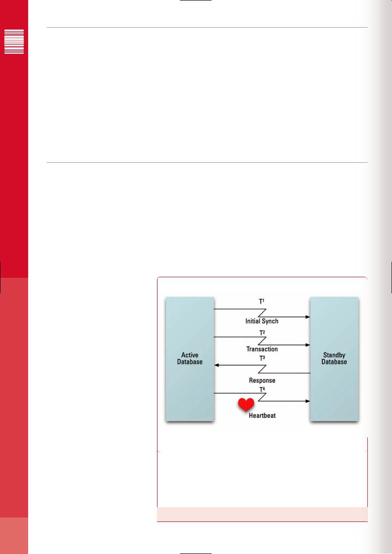
T1 |
Time within which initial synchronization must complete |
|
T2 |
Time within which Standby must receive entire transaction, once |
|
communication is initiated by Active |
||
|
||
|
|
|
T3 |
Time within which Standby must acknowledge receipt of the transac- |
|
tion |
||
|
||
|
|
|
T4 |
“Keep alive” signal to distinguish quiescent Active from failed Active |
|
database |
||
|
||
|
|
Figure 1: Time Cognizance in High Availability Inter-Process Communication
44
Put MORE throughput through.
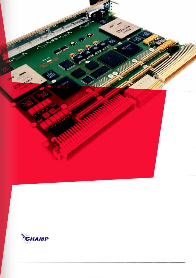
The CHAMP-FX puts the tremendous computing power of two Xilinx Virtex-II Pro™ FPGAs to work for you for digital signal processing applications where large data throughput is essential.
The CHAMP’s computing capacity is complemented by more than 10 GB/sec of I/O capability, high-speed differential serial RocketIO™, XMC/PMC sites and StarFabric interfaces. That’s a lot of power – so use it wisely.
The CHAMP-FX. Another example of the innovation and dedication that made us the leader in digital signal processing.
CHAMP-FX F E A T U R E S
•Two Xilinx Virtex-II Pro Platform FPGAs (XC2VP70 - XC2VP100)
•Two IBM 405 PowerPC™ processors per FPGA
•512 Mbytes DDR266 SDRAM
•16 Mbytes DDR II SRAM
•Two PMC/XMC mezzanine sites with Processor PMC compatibility
•Two independent, off-board StarFabric interfaces for system level connectivity
•Four 4-bit, bi-directional RocketIO ports for low latency, high bandwidth interconnect between CHAMP-FX boards or sensors
•64 Mbytes Flash for FPGA files and processor code
•Support for ChipScope Pro and JTAG processor debug interfaces
•CHAMPTools-FX developer’s kit offers VHDL libraries, development environment, reference designs, simulation test benches, BIT routines and software libraries
•Air-cooled and conduction-cooled versions
Dy 4 Systems | Peritek | Primagraphics | Synergy | Systran | VISTA Controls
www.cwcembedded.com

</Feature>
ESE Magazine January 05
<<of other processes/threads. The database management system must ensure this isolation.
Even better, the database management system should provide a means for prioritizing access to the database. In real-time systems, certain activities often have higher importance than others. For example, a navigation process would have higher priority than a background process that receives updates from groundbased systems. A database that uses a simple FIFO technique for granting access to database elements will be unaffected by prioritization of processes and threads applied at the operating system level. Developers of aerospace systems invest heavily in real-time operating systems (RTOSs) that support prioritization, but the wrong database can squander this advantage. In contrast, a database that is designed for embedded systems and is “aware” of priorities can complement prioritization at the RTOS level.
High availability
Airborne embedded hardware and software must be able to provide for redundant systems. The benefits of such redundancy range from preventing aborted missions and loss of costly equipment, to saving lives. For data management, redundancy means maintaining two or more database instances in synchronization in an active/standby configuration, with the standby database ready to take over instantly in the event the system hosting the primary database fails.
Ordinarily, the primary and standby database instances will be on separate systems connected only by a communication channel. This necessitates frequent inter-process communication to replicate changes from the primary database to the standby(s). A major challenge becomes ensuring that performance will not be unduly affected by the latency entailed by this inter-process communications. A solution is to introduce time-cognizance into the communication, so that if the active database instance does not receive acknowledgement of its communication by a pre-set deadline, it assumes the uncommunicative standby database has failed, decommissions it, and continues with normal processing. A watchdog process can then recognize the failure and optionally re-boot the system, giving the decommissioned standby database the chance to re-attach and re-synchronize. Time-cognizance in the inter-process communication channel implementation provides predictability in spite of inter-process communication latency.
Reliability
Airborne systems, like other systems on which human life depends, require the utmost reliability. When evaluating a database system’s potential contribution to reliability, consider three key attributes, for starters: Data typing, memory
allocation, and error handling.
C is the dominant programming language of embedded systems. It derives much of its power through the use of pointers. Pointers are a dou- ble-edged sword, though, allowing programs to self-destruct if used improperly. One type of pointer, the void pointer, is particularly widely used in database systems. It allows database vendors to create a common programming interface that can be used for any database design (e.g. WriteRecord( (void *) &data )).
A major drawback of void pointers, however, is that neither the C/C++ compiler nor the database runtime can validate them (that is, confirm they are used correctly). Instead, the “one size fits all” type of interface based on void pointers relies on the programmer to ensure that valid pointers are passed to the database run-time. Unfortunately, there is no guarantee a bug resulting from improperly used void pointers will emerge during testing. It could crop up after deployment, with results ranging from inconvenient to disastrous.
A safer approach – and one that we’ve implemented in McObject’s eXtremeDB – is to build a type-safe programming interface that is generated for each particular data design, when the database definition language (DDL) for that design is compiled. This eliminates the general function (like WriteRecord()) and replaces it with functions to write specific types of data, such as
Position_new( &PositionRecord ) or IFFIdentity_new( &IFFIdentityRecord ) and so on. With a type-safe programming interface, the C/C++ compiler can and will detect invalid arguments and refuse to compile the code until the error is fixed. An entire class of common database programming mistakes is eliminated. A welcome by-product of this approach is more readable and maintainable code: Position_new() conveys more information than the general WriteRecord().
Another C programming language feature used liberally by databases is dynamic memory allocation, or allocating system memory to processes on an as-needed basis at run-time. This, too, is powerful but potentially risky. Failure to diligently free (release) dynamically allocated memory when it is no longer needed or out of scope leads to memory leaks that will eventually exhaust available memory, resulting in system malfunction or failure.
Dynamic memory allocation can serve many data management purposes: database dictionaries, cache, transaction buffers, and more. While it seems logical that in-memory databases, in particular, would rely on dynamic memory (and some do), this isn’t a requirement. For greater safety, the in-memory database run-time can delegate memory assignment to the calling application, so that the application must assign a given amount of memory at a given starting address to be used for the database. This cre-
ates maximum flexibility. The application can still allocate the memory dynamically in non-crit- ical situations (entertainment systems in a commercial jet, for example), provided a memory leak will not affect more important systems.
For mission-critical systems, database memory can be treated like video memory in a flat memory model system (think old PC-DOS). A buffer is simply set aside that is dedicated to that particular task. The database run-time can use that memory to store data and all its run-time data structures (transaction buffers, connection handles, etc.) and never have to allocate memory dynamically itself. If the memory given to the database run-time is exhausted, the database run-time can inform the application and let it determine how to resolve the situation (prune the database, or find more memory to dedicate to the database).
Finally, database error handling also contributes to reliability. The database development kit should provide diagnostic capability to help ensure that the software is being used properly. Generally speaking, in a software library such as a database, errors are handled by returning the error to the application through the call stack, or by calling an error handler. For embedded systems, an error handler is the preferred technique. First, the error handler is certain to be invoked, whereas the program may not check function return codes. Second, the error handler can present a default action such as an infinite loop that would automatically cause a watchdog to restart the system.
In critical airborne systems, error handling becomes more than a development and testing concern. In a scenario where the errors are not addressed centrally by an error handler and the programmer has failed to check a return code, a program may ignore a database error code. It could continue operating with false data, with serious unwanted results when the data is relied upon for navigation, targeting or a host of other critical functions.
Conclusion
When considering data management for MilAero equipment, developers and engineering managers must inspect potential solutions at multiple levels. Database architecture must be streamlined and provide the performance needed for real-time systems. Maintaining data availability in the face of hardware or software failure must be addressed, usually with a redundant solution. Finally, developers must understand their database at the programmatic level. This is where details such as error and memory management present hidden challenges to developing and deploying highly effective aero-
space applications. |
<Ends> |
www.mcobject.com |
|
46

Embedded World - Stand 11-100

<In-Depth>
ESE Magazine January 05
UML Modeling, MDA & Real-
Time Software Development
<Written by> Michael Benkel Aonix GmbH </W>
UML and MDA are both derived from the IT sector. They do, however, have significant applications in the real-time environment.
IN THE “Unified Modelling Language Specification,” the OMG group outlines a standard notation to simplify the documentation, understanding, and maintenance
of complex software systems. Through Model Driven Architecture (MDA), the OMG provides a process to transform the higher abstraction level to application code following a series of efficient transformations. Both UML and MDA help to improve the project team’s communication and offers a clear interface to other stakeholders in the project.
But, they are primarily used in the IT space, how can they be applied to real-time software development including the generation of efficient code? Extending UML and MDA through profiles address the needs of embedded real-time applications for a high level of abstraction to model applications for high availability certification.
The UML Profile for Schedulability, Performance, and Time Specification (SPT), published by OMG in 2002, lays the foundation for describing the aspects of real-time systems. Although SPT offers good guidelines, it is too general for many applications and does not provide any hints on how to implement the described extensions.
To bring the fundamentals of SPT to the customer, an industry consortium defined the High Integrity Profile (HIP) to meet certification standards such as ARINC 653 and Ravenscar. By profiling these high-availability standards, HIP improves developer productivity and real-time software reliability.
Available standards
There are several certification standards available for the implementation of real-time applications. The ARINC 653 standard, developed by the avionics community, defines an RTOS API for a specific avionics platform that supports space and time partitioning. It also provides several patterns, such as Blackboard, Buffer and Event, for implementing communication between independent processes.
The Ravenscar profile, defined in 1997, was specified with reference to the Ada programming language. Ravenscar is based on a lan- guage-independent set of building blocks that
are suitable for constructing typical real-time systems, and as input to analysis tools to provide evidence that the concurrency requirements of the system have been met.
To model a real-time application, we begin by extending the standard UML profiles using Stereotypes and Tagged Values as defined in the SPT specification. In addition to providing the basic concepts for real-time modelling, SPT defines several constructs for specifying timing relationships. It specifies start and end time tags or duration tags, which can be used to capture time budgets in the UML model. These budgets represent the maximum time allowed for an action or message (worst-case execution time), and the tags are used in sequence diagrams and state charts to limit the time available for critical code. Unfortunately, SPT does not give guidelines how to map this information to source code and specific real-time communication patterns are missing as well.
HIP
The High Integrity Profile (HIP), which consists of standard design patterns, addresses common real-time programming problems and brings together certification standards required for high-availability systems. It provides a subset of profiles for OMG’s SPT, using SPT elements are used wherever possible to minimize disparity.
HIP aims to define the minimal set of abstractions suitable for hard real-time systems conforming to the Ravenscar model. Some common asynchronous communication paradigms coming from the ARINC 653 have been added for concurrency synchronization. HIP has been designed to enable real-time analysis like RMA to be done on the model itself, primarily using three SPT stereotypes: <<SAtrigger>>, defining activating events (periodic threads, triggers)
<<SAaction>>, defining atomic actions (methods)
<<SAresource>>, defining shared resources (classes, objects, members, etc)
Since real-time software designers usually need to map software components to processes, threads or tasks which are higher level than just triggers and actions, additional stereotypes have been introduced to represent concurrent units.
Figure1: Blackboard Example
First, the abstract class stereotype <<HIautoTask>> was defined as inheriting from the pattern <<SAaction>> in association of an event itself stereotyped <<SAtrigger>>. Then two concrete class stereotypes were defined:
<<HIperiodic>>, represents the set of actions (response) performed each time a periodic timing signal occurs (trigger)
<<HIsporadic>>, represents the set of actions (response) performed each time an event signal occurs (trigger)
To synchronize concurrent units, new stereotypes dealing with resource sharing and asynchronous communication have been defined. The following patterns have been introduced:
<<HIpriorityCeilingEmulation>>, for resource sharing
<<HIbuffer>>, for the bounded buffer communication paradigm
<<HIblackboard>>, for the persistent data broadcast communication paradigm <<HIevent>>, for the classical event notification paradigm
With these stereotypes, HIP covers the main areas concurrency, resource sharing, and asynchronous communication. The stereotypes can be used in class diagrams to give a static view of the system class structure, in sequence diagrams to model the interaction between objects, and in state diagrams to model the dynamic behaviour within a class. This allows an architect to insert information about the number of real-time tasks, frequency of particular real-time tasks execution and anticipated
worst-case execution times for each task in the>>
48

4HE %MBEDDED -ASTERCLASS
/. 4(% 05,3%
%-"%$$%$ -%$)#!, $%6%,/0-%.4
&REE %MBEDDED 3EMINAR
,OCATION #AMBRIDGE $ATE 4HURSDAY TH -ARCH
4HIS SEMINAR WILLIBE ANREXCITING AND POWERFULNCOLLECTION OF TECHNICAL PRESENTATIONSARELATINGTTO THE DEVELOPMENT OF EMBEDDEDBSYSTEMSEIN THE MEDICAL SECTOR 4ARGETEDTAT
EMBEDDED DEVELOPERS THISESEMINAREOFFERS THE OPPORTUNITY TOP HEAR THE LATESTEDEVELOPMENTS AND CONCEPTSLTHAT AREEDRIVINGI THIS TECHNOLOGY
7HETHERTYOUEAREEA DEVELOPERVOF MEDICAL SYSTEMS ORMSIMPLY ANA EMBEDDED ENGINEER SEEKINGITO KEEPRUP TOEDATE IWE FEELTSUREE YOUOWILL lND THIS AlGOOD INVESTMENT OF YOUROTIME
&OROARFULL AGENDALAND REGISTRATIONRPLEASE VISIT
WWW EMBEDDED MASTERCLASS CO UK
</In-Depth>
ESE Magazine January 05
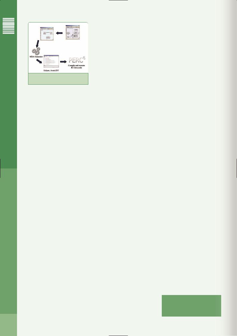
Figure 2: HIP Tool Chain
<< platform independent model assertions.
Other diagram types such as use case diagrams, which are intended to document user interaction with the system, are not extended by HIP. They can be used as additional documentation or as part of requirements analysis.
HIP example
Consider two independent classes (tasks) and a communication mechanism. A class Score defines a method collect():String to collect results. To display the results, there is a class Result with method display(result:String). Both classes are periodic threads with certain priorities.
To exchange date between these two threads, we use a “blackboard”, so that they can send and receive messages. With this pattern, the receiver always reads the last message and incoming messages always overwrite the last message.
Using the HIP profile, it is very easy to model such an application. Since both classes are independent tasks, they are marked with Stereotype
<<HIPeriodic >> or <<HISporadic>>. To use a Blackboard as the communication mechanism, the association between two tasks is marked with the stereotype <<HIApexBlackboard>>. Figure 1 shows the UML model of this example looks like. The association class Data is used to define the type of the information exchanged between the two classes.
Implementation of the profile
HIP also defines the implementation of the stereotypes. The transformation is based on MDA, and special templates describe how the high-level model is mapped to the target environment. This makes mapping very flexible, the application can be modeled independently of the target language and new requirements are easy to implement.
Each MDA platform requires a UML profile as its semantic underpinnings, and this has an impact on the model transformation for the target system. MDA modeling starts on a higher level of abstraction with the creation of a platform independent model (PIM) mostly in UML notation. The PIM is then mapped to one or more platform spe-
cific models (PSM) by adding technical aspects and the PSM is then mapped to the target environment by using implementation patterns.
The mapping is done by a transformer and transformation rules to automate these steps. MDA makes reuse of design models easier, since platform dependencies are added later, the same design model can be used in many different settings.
The following example shows what an implementation in Java looks like. Based on the stereotypes used, several constructs are generated automatically in the source code. Score extends PeriodicThread, three additional attributes are generated and initialized, and a special construct and a method public void handlePeriod() are generated.
public class Score extends PeriodicThread {
private static int priority = 5; private static RelativeTime period =
new RelativeTime(100 * 1000,0); private ScoreResultBlackboard
scoreResultBlackboard;
..
public Score(ScoreResultBlackboard connector) {
..
super(priority, period); scoreResultBlackboard = connector;
}
public void handlePeriod() {
..
}
}
Attributes priority and period are initialized with the tagged values and attribute scoreResultBlackboard is the connection to the artificially created blackboard class (see below). It is set in the constructor above. The constructor invokes the superclass constructor with priority and period of class Score.
In the method body of handlePeriod(), some code has to be filled in manually. The run() method of super¬class PeriodicThread invokes handlePeriod() periodically with the time value specified in attribute period. This is what the handlePeriod() method might look like:
public void handlePeriod() { Data data = new Data(collect());
scoreResultBlackboard.write(data);
}
A new Data object is constructed and written to the blackboard instance. In collect(), everything could be implemented, but for now, a dummy implementation might be sufficient.
public String collect() { String retVal = "";
retVal = new Date(System.currentTimeMillis()).toString();
return retVal;
}
To automate as much as possible in the HIP development process, a full tool chain is available, starting with the Ameos modeling tool where the user can describe a high-level view of the system. All stereotypes of HIP are defined in the Ameos profile editor and assigned to the appropriate elements of the UML meta-model, which assures easy and correct use in the modeling tool.
The transformation in the target environment is carried out by the MDA generator of Ameos. As described earlier, this is a two step process. During the first step, a platform specific model is generated by implementing technical pattern like the blackboard. Finally, the PSM is mapped to the target environment by implementing it in Java, for example.
In an IDE like Eclipse or AonixJDT, the user can then implement the missing pieces of the application. The Java code can then be executed with the PERC Virtual Machine (VM) supporting the execution of real-time Java platform applications in embedded systems.
Summary
Using a profile, UML has a standard way of extending its semantics by stereotypes, constraints and tagged values. With the help of profiles, the UML can be adapted to applications for which standard UML is not specific enough.
HIP represents an implementation of modeling real-time software for embedded systems using UML and Model Driven Architecture. This approach demonstrates that it is possible to automatically generate source code for realtime applications from the high-level architectural models. Model checking capabilities allow design inconsistencies to be identified and corrected early in the development process.
The HIP profile aims to be compliant with standards such as ARINC 653 and Ravenscar, and at the same time meet the specific needs for high-integrity applications. To achieve this, it uses parts of the SPT real-time profile and communication patterns from the ARINC 653 standard. The MDA-based code generation brings reducing costs of development, better quality and reuse of domain aspects to the real-time market. High-level problem-specific models are transferred by a transformer in safe and coherent source code.
As a result, HIP is a lightweight and easy to use UML profile, suitable for a wide range of applications in many different branches of industry such as avionics, automotive and telecommunication. <Ends>
www.omg.org/uml
www.omg.org/mda
www.arinc.com
www.aonix.com
50