

Atmel applications journal.Summer 2004
.pdfA T M E L A P P L I C A T I O N S J O U R N A L
available; we will use mutual authentication and data encryption to also protect the History Zones. We can use the same key assigned to debit locations for decrementing the Value Zones to give full access to the History Zones. For the Laundry History Zone, we will use authentication key 1; the Access Register = $D7 and Password Register = $7F. For the Parking History Zone, we will use authentication key 3; the Access Register = $D7 and Password Register = $FF. The keys used for each zone are summarized in Figure 3.
Identifying the Card
Being compliant with ISO 7816-3, CryptoMemory provides an answer to reset (ATR) when inserted into a standard ISO compliant card reader. This 8-byte value automatically sent from the card to the reader is used to identify the card’s communication properties and may also be used to identify the application for which the card was designed. The AT88SC0104C ATR provides for two “historical bytes” that may be used to identify the card as a “laundry/parking” stored value card. This ATR value is defined in the Configuration Zone of the AT88SC0104C where a total of 61 bytes are available to identify the card, the manufacturer, the issuer or the assigned holder of the card. Figure 4 shows the contents of the Configuration Zone with areas available for these identification fields highlighted.
Of the 61 bytes available, it is advised that the ATR comply with ISO 7816-3 for use in standard card readers and that the identification number be a unique number assigned to each individual card. Aside from this, the remaining 46 bytes may be used to store issuer data, the name of the
|
Component |
Size |
|
|
Answer to Reset |
8 bytes |
|
|
Fab Code |
2 bytes |
|
|
Memory Test Zone |
2 bytes |
|
|
Card Manufacturer's Code |
4 bytes |
|
|
Lot History Code |
8 bytes |
|
|
Device Configuration Register |
1 bytes |
|
|
Identification Number |
7 bytes |
|
|
Access Registers |
4 bytes |
|
|
|
|
|
|
Password/Key Registers |
4 bytes |
|
|
|
|
|
|
Issuer Code |
16 bytes |
|
|
Reserved |
24bytes |
|
|
Authentification Attempts Counters |
4 bytes |
|
|
|
|
|
|
Cryptograms |
28 bytes |
|
|
|
|
|
|
Session Encryption Keys |
32 bytes |
|
|
|
|
|
|
Secret Seeds |
32 bytes |
|
|
Password Attempts Counters |
16 bytes |
|
|
|
|
|
|
Write Passwords |
24 bytes |
|
|
|
|
|
|
Read Passwords |
24 bytes |
|
|
|
|
|
|
Reserved |
16 bytes |
|
|
|
|
|
|
|
|
|
|
|
|
Zone |
Read Access |
Debit Only |
Full Write Access |
Access Register |
Password Register |
|
|
|
|
|
|
|
|
|
|
|
Laundry Value |
0 |
Keys0,1 |
Key 1 |
Key 0 |
$C7 |
$1F |
|
|
Laundry History |
1 |
Key 1 |
none |
Key 1 |
$D7 |
$7F |
|
|
Parking Value |
2 |
Keys 2,3 |
Key 3 |
Key 2 |
$C7 |
$BF |
|
|
Parking History |
3 |
Key 3 |
none |
Key 3 |
$D7 |
$FF |
|
|
|
|
|
|
|
|
|
|
|
|
|
|
|
|
|
|
|
Figigure 3: Security Access Keys
cardholder, account number, etc. Once the card is issued, the information in these fields will always be readable but cannot be changed.
Preparing the Card for Use
To prepare the card for use as a stored-value card, the initial data needs to be programmed, security settings made and the proper keys loaded into the card. In this example, we will consider a two-step process where most of this information is loaded at the factory, and the final data, including information concerning the end user, is loaded at the time of card issue. Both of these operations need to be under strict control of the issuing authority, keeping both the cards and the data programmed inside the cards secure until a card is issued and delivered to the end user. Most of the information may be loaded into the card at the factory, using automated equipment and following this sequence.
•Write both Value Zones to all 0s to indicate zero initial value. The History Zones may be set to an initial value at this time, if desired; they will be programmed to all 1s as they are received from Atmel.
•Present the Secure Code to obtain access to the Configuration Zone. At this time, the Secure Code should be changed to a value defined by the issuing authority; this code will protect the card until it is issued and given to the end user.
•Write the ATR register to a value that will indicate the
type of card to the application when it is inserted a reader in the field. Care should be taken to keep this value compliant with ISO 7816 standards. The card manufacturer code may be written to indicate the manufacture location,manufacture date, etc.
•Write a unique ID number for each card into the Identification Number field.
•Write initial cryptogram values into the four fields provided. Random numbers are suggested, as these
will be used as seeds for the first authentication with each key. These fields are automatically updated by the device with each successful authentication.
•Write the four secret seeds. These are the authentication keys that will control access to the user zones. These keys should be diversified by the unique ID number and thus are unique for each individual device.
•Write the access registers and password registers to the previously determined values. Once these registers are written, all access to the User Zones (Value Zones and History Zones) is controlled by the security settings and authentication keys selected.
•Write the FAB fuse and CMA fuse. The FAB fuse
will lock the value of the ATR and the CMA fuse will lock the value of the card manufacturer code.
Once factory programming is complete, the only information remaining to be programmed into the card is data specific to the issuing location and the end user. This is typically done one card at a time with the end user present and supplying his personal information. The following sequence is required for the final step in issuing the card.
•Present the Secure Code for access to the Configuration Zone.
•Write any issuer data specific to the issuing location or date.
•Write any user specific data into the card. The Issuer Code area (16 bytes) and the Reserved area (24 bytes) may be used to store this information and will be locked by the PER fuse.
•Write the PER fuse. Access to the Configuration Zone is no longer allowed after this fuse is written. Initialization of the card is complete and it is ready to be loaded with value.
Figure 4: AT88SC0104C Configuration Zone
www.atmel.com |
page 39 |
|

A T M E L A P P L I C A T I O N S J O U R N A L
Using the Card
Two basic operations are performed on the storedvalue card once it is issued to the end user: credit and debit. Immediately following (or possibly combined with) the issuing of the card, the initial value will be loaded onto the card. This operation will be the same as reloading more value to the card at a later time; both are credit operations. Loading value to the card will take place at a trusted station and will typically be manned to avoid equipment tampering and to ensure proper payment from the user. The sequence for loading value to the card follows.
•Read the ATR from the card to determine if it is a valid card for the application.
•Read issuer and user data from the card. This data may be used to track use at a specific station or further validate the card at the station where it is being used.
•Read the identification number from the card. This will be required for the reader to calculate the specific keys to use for authenticating with this specific card.
•Authenticate with key 1 or 3 to gain read access to the Value Zone and full access to the History Zone. The key used depends on whether the card is being loaded for a laundry or parking application.
•After a successful authentication, initialize data encryption with the card. Through the Access Registers, we required data encryption, so even if authentication is successful, the data will not be readable until encryption is initialized.
•Read the value zone and decrypt to determine the current value of the card.
•Read the History Zone and decrypt.
-Compare the latest record to value zone data; the two should match.
-Identify the oldest record in History Zone as the location to write the historical record for this transaction.
•At this point, the application software needs to determine the value that will be credited to the card based on the value supplied by the user for this transaction and the $64 maximum value that the card may hold. For every $0.25 that is to be added, one bit in the Value Zone will be written from a 0 to a 1 state.
•Encrypt data and write the History Zone, overwriting the oldest record.
•Authenticate with key 0 or 2 to gain full access to the Value Zone, initialize data encryption.
•Encrypt data and update the Value Zone by writing the appropriate bits to 1.
•Power down the card to complete the
transaction and close all security access to the card.
Once the card has been loaded with value, it may be used to purchase goods or services (laundry or parking, in this example) at an authorized POS station. In our example, it is likely that these stations will be unattended to provide convenience to the user and efficiency to the system provider. An unattended station may be more prone to attack by someone attempting to illegally load value to a card. For this reason, separate keys are used for credit and debit operations, and the POS stations will only hold the keys to remove value from a card.
A sequence of a debit operation is as follows:
•Read the ATR from the card to determine if it is a valid card for the application.
•Read issuer and user data from the card. This data may be used to track use at a specific station or further validate the card at the station where it is being used.
•Read the identification number from the card. This will be required for the reader to calculate the specific keys to use for authenticating with this specific card.
•Authenticate with key 1 or 3 to gain read access to the value zone and full access to the History Zone. This key will also give access to decrease the Value Zone by writing bits from a 1 to 0. The key used depends on whether the card is being used for a laundry or parking application.
•After a successful authentication, initialize data encryption with the card.
•Read the Value Zone and decrypt to determine the current value of the card.
•Read the History Zone and decrypt.
-Compare the latest record to Value Zone data; the two should match.
-Identify the oldest record in History Zone as the location to write the historical record for this transaction.
• The cost of the services requested by the user is compared to the current value of the card. If sufficient, the card may be debited for the services requested. For every $0.25 that is to be debited, one bit in the Value Zone will be written from a 1 to a 0 state.
•Encrypt data and write the History Zone, overwriting the oldest record.
•Encrypt data and update the Value Zone by writing the appropriate bits to 0.
•Power down the card to complete the transaction and close all security access to the card.
•Provide the services to the user.
Antitearing Provides Further Protection
For critical writes to the card, such as updating the Value Zone, additional protection is provided to ensure what was intended to be written will be written. The technique of “tearing” the card from the reader during the transaction is not uncommon for those who try to obtain goods or services before value is deducted from their card. This is especially true at unattended POS stations. CryptoMemory offers a write with antitearing feature built into the device logic that will prevent the tearing attack. Internal buffers and registers are used to ensure the data is written properly to the EEPROM either before a tear occurs or upon the next card power-up if the card is torn.
Extending the Electronic Purse Example
In this article, we used the smallest CryptoMemory device to design a stored-value card to include two separate applications. If more memory is needed to store larger values or record more information, larger CryptoMemory devices are available up to 256 Kbits of EEPROM. We used two authentication keys for each application in this example; four keys are available that could support four unique applications on one card. Read and write encrypted passwords (a total of eight unique sets) are also available that could be used to further distinguish credit and debit operations if one authentication key is used for each of four applications. CryptoMemory offers the built-in security features for stored-value applications and flexibility in size and use of these features to create the ideal card for many electronic purse programs. Similar to the electronic purse is the loyalty program, also using a stored-value card, but instead of storing monetary value, loyalty points are accumulated for redemption at a later time. The same techniques used in this example can easily be applied to a loyalty program. 
www.atmel.com |
page 40 |
|
A T M E L A P P L I C A T I O N S J O U R N A L
An Implementation of Electronic Purses
Using Atmel’s CryptoMemory® Device
By: An Van Le and Anthony Kim, EFM Company
One of the key applications of smart cards is electronic payment via electronic purses residing on the smart cards. With an e-purse, a cardholder may purchase items from vendors who participate in the payment network, as he would with cash.
Smart cards have been widely used in several parts of the world, especially in Europe and Asia. One of the key applications of smart cards is electronic payment via electronic purses residing on the smart cards. With an e-purse, cardholders may purchase items from vendors who participate in the payment network, just as they would with cash.
Smart card applications, including those that involve electronic transactions with e-purses, have not been widely deployed in the U.S. for various reasons. However, one of the sectors where smart cards have attracted some interest is on the over 6,000 college campuses in the U.S., where smart cards are used with electronic purses for purchases and other transactions carried out at campus facilities.
accessed only after the chip authenticates a user via a password or a limited challenge-response scheme.
Recently, there has been considerable interest in deploying secure memory smart cards for use in copier payment systems, multi-housing laundry systems, parking, etc. One key reason is that the secure memory card costs significantly less than the processor-based card. When the number of deployed cards is large, the cost savings could be significant. In this article, we will discuss our implementation of e-purses on a new type of smart card chip: the Atmel CryptoMemory® chip. The smart cards that contain these chips must coexist with the existing processor-based smart cards and must operate with the existing transaction system.
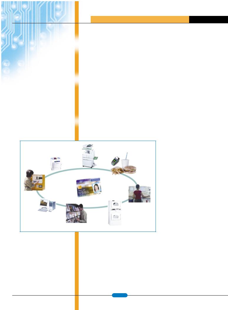
Figure 1: Typical uses of CryptoMemory smart cards in a campus environment
Currently, in many smart card campus projects, the smart cards are based on chips with a central processing unit (CPU). These cards are often referred to as processor-based smart cards or processor cards for short. On the opposite end of the capability spectrum of smart cards are those based on chips that do not have a processor. These smart cards are commonly referred to as secure memory cards, as their main function is to store data in the nonvolatile memory on the chip. This data can be
The CryptoMemory Card
The CryptoMemory card can be considered a hybrid between the secure memory card and the processor card. It embodies the properties of the secure memory card in the following ways:
•The card contains logic for managing nonvolatile memory, for controlling access to the memory, and for communicating with an external interface device (IFD).
•Since the card provides a basic set of functions, applications developers need not be concerned with developing their own card-operating system or on-chip application; they only need to use the provided functions in a secure and effective manner.
The CryptoMemory card embodies the properties of the processor card in the following ways:
•The card is capable of performing mutual authentication with an IFD, such as the reader, albeit the mutual authentication is implicit. This is based on an Atmel-specific challengeresponse protocol.
•The card is capable of communicating with the IFD via the smart card T=0 protocol.
•The card contains encryption capability to protect the privacy of data exchanged between the card and a terminal.
www.atmel.com |
page 41 |
|

Security Requirements for
E-purse Applications
EFM Company has developed a transaction system, named Potentia, for conducting payment transactions in campus settings. CryptoMemory cards will be integrated into Potentia. Therefore, the CryptoMemory cards are subject to a set of security requirements similar to those used in the processorbased cards. These security requirements, as well as some key functional requirements of the transaction system, can be iterated as follows:
•Each CryptoMemory card must contain a unique set of keys and cryptographic variables to safeguard the system in the event of a security breach of a single card. Should the security of one card be compromised and lead to exposures of key values, other cards would not be affected.
•The user experience with the CryptoMemory cards must be the same as that of a processor card. In other words, a cardholder need not be aware of what type of card is being used. The terminals and other interface devices must be able to recognize different card types and issue the appropriate commands to the cards to carry out a requested transaction, transparent to the user.
•The CryptoMemory card must be able to verify the authenticity of terminals and other interface devices that participate in the payment system, and proceed to conduct transactions with a terminal only after it has successfully authenticated the terminal.
•The CryptoMemory card must be able to detect the replay of old data and transaction messages by hostile terminals and reject them.
•The CryptoMemory card, in conjunction with the terminals, must be able to store and maintain the balance of the purses as well as other userspecific data with a high level of integrity.
•The CryptoMemory card and other components of the transaction system must provide audit trails, via records or a log of the transactions. The transaction records must be attached with a cryptographically strong electronic signature to insure a high level of integrity.
The transaction records help detect fraudulent attempts by ill-intentioned cardholders or vendors who sell services on the campus and participate in the payment network. For example, when all the transaction records for a period have been collected
A T M E L A P P L I C A T I O N S J O U R N A L
at the backend server, the balance amount and the transaction amount in each record will enable detection of “gaps” and help determine whether a student or a vendor was attempting to cheat by manipulating the balance of the purse.
Implementation and Deployment
Figure 1 illustrates various devices incorporating components of the Potentia – the transaction system developed by EFM – to conduct electronic payments for many on-campus purchases.
In this system, the students are issued non disposable smart cards, which are based on processor cards as well as CryptoMemory cards. Each card contains one or more e-purses, depending on the card issuer. When a card is first issued to a student, the purse(s) on the card would be empty. A student can use a cash-to-card machine, which accepts either cash or credit card from the student and transfers a corresponding amount to the purse on the card. Once the purse is filled, the student can use the card to pay for various activities: printing, copying, laundry, purchasing meals or books.
Since various chips in the Atmel CryptoMemory family provide from 4 to 16 user memory zones, 4 to 16 separate purses can be implemented. This is more than what is typically needed.
A critical component of Potentia that resides in the cash-to-card machines, the POS terminals, and the card readers of the vending machines or the copiers is a small hardware module referred to as the Security Access Module (SAM). The SAM is developed on an Atmel smart card chip, the AT90SC3232CS. This SAM is a highly secure cryptographic processor where all the computations involving sensitive keys take place during debit or credit transactions. A secure module like the SAM is needed because in order to make a debit or a credit to the purse on the card, an interfacing terminal must prepare a cryptogram or encrypted message (to prevent unauthorized modifications) and submit it to the card.
Another critical component of the transaction system, but not shown here, is the transaction server, which performs many tasks in the backend, including verifying the integrity of all collected transaction records, reconciling transaction amounts on all terminals on a periodic or on-demand basis, and managing all the devices deployed within the payment system.
In addition to storing the e-purses, the card also stores information pertaining to the student cardholder, such as course enrollment and library
checkouts. To maintain privacy of the information in the event the card is lost or stolen, a terminal or interface device must submit an access PIN to the card for authentication before the card can provide access to the information.
Since the CryptoMemory card does not differentiate purse data from other data, we implemented the purses in user zones separate from cardholder’s data, such as enrollment information. This separation ensures that a terminal authorized only to access the student’s enrollment information would not be able to tamper with the e-purse balance.
The CryptoMemory card provides independent access controls for reading and writing data. Thus, conceptually, a straightforward implementation for the e-purse can be described as follows:
–Define the read access to the purse balance to be “free”— meaning the purse can be read without any required key or password.
–During a debit or credit transaction, the terminal reads the balance of the e-purse on the card and subtracts or adds to it the
transaction amount. The terminal then, by way of the SAM, submits a “Write password” in encrypted form to the card for authentication before the terminal can write the new balance to the purse after a credit or debit operation. Furthermore, to prevent unauthorized modifications of the purse balance during transmission, the new balance is encrypted, and a checksum is included to maintain integrity.
This would enable any terminal to read the balance of the purses, but only an authorized terminal with a secure SAM can do transactions and write the new balance to the card.
Our purse implementation requires that purchase amounts above a predetermined amount, say $20.00, require the cardholder to submit a PIN and be authenticated before the transaction can take place. This PIN is referred to as the maximum debit PIN. To meet this requirement on the CryptoMemory card, we write the maximum debit PIN on the card as part of the e-purse data. For security reasons, this PIN is stored on the card in encrypted form, using the Advanced Encryption Standard (AES) — independent of the stream cipher implemented on the card. At the start of the debit transaction, when the terminal reads the current balance of the purse from the
www.atmel.com |
page 42 |
|
A T M E L A P P L I C A T I O N S J O U R N A L
Anthony Kim, CEO, EFM Company
Anthony Kim founded EFM Company in 2000, to provide electronic student portfolios in campus cards. Mr. Kim co-founded DA Management, a management/consulting company, in 1997, working with several Silicon Valley corporations. He has 10 years experience in management and finance and has served on the advisory board of Raining Data Corporation. He graduated from Cornell University and received the distinguished Charles Goodwin Sands Medal.
An Van Le, CTO, EFM Company
An Van Le led the development of EFM’s Transaction system in 2002. Prior to EFM, Mr. Le held senior management and technical positions at leading technology companies. He holds over 25 patents, has published over 20 technical documents, and received seven IBM Invention awards.
Mr. Le holds a MS in electrical engineering/ computer science from the University of Utah.
Acknowledgements
The authors wish to express their appreciation to Bryce Hilton, who led the firmware implementation at EFM for the SAM used in our transaction system and provided useful comments for this article. We also wish to acknowledge another colleague, Richard Luong, for his contributions to the development of the transaction server.
card, it also reads the encrypted PIN if the debit amount is above the predetermined limit. The terminal then provides the SAM with the retrieved (encrypted) PIN as well as the PIN supplied by the cardholder. The main processing steps carried out by the SAM are as follows:
–The SAM derives an AES key unique to the chip and uses it to decrypt the encrypted PIN retrieved from the e-purse of the CryptoMemory card. The result is the reference maximum debit PIN is available for comparison.
–The SAM compares the PIN entered by the user with the reference maximum debit PIN. If they are equal, the SAM continues with the transaction and prepares a new balance to be written back to the card, encrypted under the stream cipher.
–If the two PIN values do not match, the SAM convey the error to the terminal, which in turn aborts the transaction and displays an appropriate message to the cardholder on the incorrect PIN.
Before the cards are deployed, an important step is to inject the cryptographic variables — the secret seeds, initial Cryptograms, and passwords — onto the configuration zone of the cards in a secure manner during the card issuance process. The CryptoMemory card will use these cryptographic variables subsequently as it carries out mutual authentication processes with the terminals and as it exchanges encrypted data with the terminals.
When the CryptoMemory cards are shipped from the card manufacturer’s facility, the security of the cards is protected by a secret transport code. The card issuer is provided with the transport code via a protected communication channel or secure courier. To personalize the cards as part of the process, the card issuer must submit the correct transport code to the CryptoMemory card before the cryptographic variables can be stored on the card. Currently, the data to be written to the configuration zone can only be transmitted to the card in clear form. This means that the card issuance process to inject these secret values onto the card should be performed at a highly secure facility to ensure the values transmitted to the card during this process are not intercepted. Our solution to this issue involved three steps:
–Split the issuance process into two processes: an initialization process and a personalization process. The initialization process is where the
secret values of the cryptographic variables are injected onto the card, this process is only performed at a physically secure facility. The personalization process is where personalized data specific to a student, including the maximum debit PIN discussed earlier, is written to the card. Since the values written to the card during the personalization process can be encrypted under the keys derived from the values injected during the initialization process, the personalization process can be performed in a public setting of the campus, without any security concerns, at the time a student applies for the card.
–Use key diversification based on a set of master keys and the ID of the card to derive unique values of the cryptographic variables before injecting them onto each card. This is also to be in step with the earlier described requirement of unique key values for each card. Thus, in the worst case, if there were a weakness in the physical security of the initialization facility that enabled an adversary to intrude and intercept secret values transmitted to a number of cards, the security exposures would be confined to those cards. Needless to say, the derivation of unique values for the cryptographic variables are performed inside the secure boundary of a specialized cryptographic adapter or SAM to maintain the secret values for the set of master keys.
–Utilize specialized readers and initialization equipment that prevent wire-tapping and interception of secret values written to the card during the initialization process.
The security of the whole transaction system is dependent on the security of each component, how well the components are integrated into the system, and whether interactions between components are well designed. The built-in features of the CryptoMemory card have helped enable us to meet the security and functional requirements stated earlier for e-purses. The cards coexist well with the processor cards in our transaction system.
We have found the CryptoMemory card offers a balanced trade-off between security, cost, and features. Its security features and the reasonable sizes of storage are unmatched by the secure memory cards from various vendors, while its functional features and low cost make it an attractive candidate to replace some of the low-end processor cards. 
www.atmel.com |
page 43 |
|
A T M E L A P P L I C A T I O N S J O U R N A L
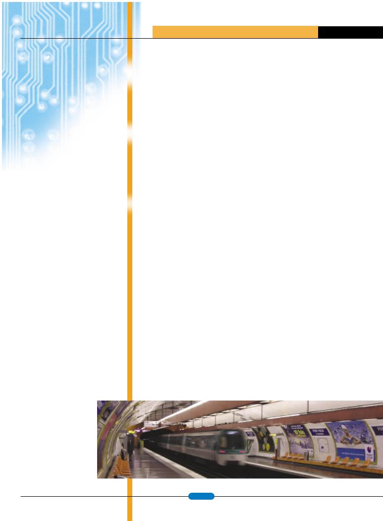
WHETHER THE NEED IS FOR A SUBWAY SYSTEM, BUS OR RAIL SYSTEM, A CONTACTLESS CARD OR TOKEN CAN BE UTILIZED QUICKLY AND AFFORDABLY.
CryptoRF™...A Secure Contactless Solution
By: Jean Pierre Benhammou and Mary Jarboe
For the last three decades, smart cards and smart card readers have provided a viable system for processing e-purse, access control, loyalty, parking meter and other applications. But what about the needs of the transportation industry where bus and subway systems need a faster, more secure method for people to easily and quickly access their systems? A contactless or RF interface with security is the solution Atmel engineers created with CryptoRF™.
In a bus or subway system, the prepaid contactless card or token can be carried in a wallet or purse. The wallet or purse can simply be put in close proximity to the reader, and the proper monies are deducted.
Whether the need is for a subway, bus or rail system, a contactless card or token can be utilized quickly and affordably. In a bus or subway system, the prepaid contactless card or token can be carried in a wallet or purse. The wallet or purse can simply be put in close proximity to the reader, and the proper monies are deducted. The Paris subway systems are currently using this technology and have reported a major cost reduction in both fraud and maintenance expense; there is no possibility of wear and tear or contamination since the readers are sealed. For commuters, this translates into ease and swiftness in boarding the trains.
With the growing need for security in today’s world, CryptoRF offers a low cost, high security solution for numerous applications that require limited location access and personal identification authentication, including government travel documents. With its easily implemented interface and multiple levels of memory and security, a previously simple building access system, using a contact card inserted into
readers, can quickly and cost effectively be transformed into a secure contactless system with biometric security. Even higher security can be achieved when a photo ID is added to the card by simply using a higher memory density within the CryptoRF family of devices.
Another interesting application for CryptoRF that has emerged in the marketplace is the protection of product authenticity against fraud. Imagine boxes of prescription drug bottles going down a conveyer belt to a loading dock for delivery to retail locations. With a CryptoRF device on the labels, each individually packaged product can be identified and authenticated as an official OEM product as it leaves the manufacturer and everywhere along the distribution system until it reaches its destination – without any contact between the reader and the product itself. Inventory control or documenting the history of the use of a product becomes an additional advantage to using an RF interface. The data is easily stored and secured within the device for access and use only by authorized personnel. This concept is currently being used in applications such as printer and toner cartridges and extensively in the medical field and chemical industry.
Several emerging countries have created pre-paid energy systems to ensure payment of home and business energy use. Initially contact cards were used, but it was soon discovered that these could be tampered with by inserting liquid into the card slot and disabling the meter. The solution was a contactless system using CryptoRF. With a meter sealed on the outside, the prepaid contactless card can be placed in close proximity to the meter, and the monies are automatically registered in the consumer meter. These contactless energy cards and meters protect against tampering and ensure the reliability of the entire system. 
|
|
www.atmel.com |
page 44 |
|

A T M E L A P P L I C A T I O N S J O U R N A L
Considerations for RFID Technology Selection
RADIO FREQUENCY IDENTIFICATION
|
SYSTEMS OPERATE IN THE ISM |
|
|
|
|
|
|
By David Dressen |
|
|
|
|
|
|
|
|
|
|
|
|
|
Active transponders contain a battery or are |
|||||||||||||||||||||||||||
|
RADIO FREQUENCY BANDS WHERE |
|
|
Secure RF Product Development Manager |
|
|
connected to an external power source. |
Passive |
|||||||||||||||||||||||||||||||||||||||||
|
|
|
Radio |
Frequency |
Identification |
|
(RFID) systems |
transponders are powered by the RF field. Passive |
|||||||||||||||||||||||||||||||||||||||||
|
|
|
|
|
|
|
|
|
|
|
|
|
|
|
|
|
|
|
|||||||||||||||||||||||||||||||
|
NO RADIO LICENSE IS REQUIRED. |
|
|
|
transponders |
are smaller, |
have |
lower cost, and |
|||||||||||||||||||||||||||||||||||||||||
|
|
|
consist |
of an electronic |
data |
carrier |
device |
and |
|||||||||||||||||||||||||||||||||||||||||
|
|
|
|
|
|
|
|
|
|
|
|
|
|
|
|
|
|
require no periodic maintenance. Active transpon- |
|||||||||||||||||||||||||||||||
|
EACH FREQUENCY BAND HAS |
|
|
|
|
|
|
reader that communicate information using radio |
|||||||||||||||||||||||||||||||||||||||||
|
|
|
|
|
|
|
ders are capable of longer communication distance |
||||||||||||||||||||||||||||||||||||||||||
|
|
|
|
|
|
|
|
|
|
|
|
|
|
|
|
|
|
technology. |
The contactless transfer of data has |
||||||||||||||||||||||||||||||
|
ADVANTAGES AND LIMITATIONS |
|
|
|
|
|
|
and can perform data collection tasks even when no |
|||||||||||||||||||||||||||||||||||||||||
|
|
|
|
|
|
|
numerous applications in commerce and industry. |
||||||||||||||||||||||||||||||||||||||||||
|
|
|
|
|
|
|
|
|
|
|
|
|
|
|
|
|
|
reader is present. |
|
|
|
|
|
|
|||||||||||||||||||||||||
|
WHICH MUST BE CONSIDERED |
|
|
|
|
|
|
RFID is more flexible than optical, magnetic, and |
|
|
|
|
|
|
|||||||||||||||||||||||||||||||||||
|
|
|
|
|
|
|
|
|
|
|
|
|
|
|
|
|
|||||||||||||||||||||||||||||||||
|
WHEN DESIGNING AN RFID SYSTEM. |
|
|
contact smart card technology. |
|
|
|
|
|
|
|
|
The simplest RFID devices are single-bit electronic |
||||||||||||||||||||||||||||||||||||
|
|
|
|
|
|
|
|
|
|
|
|
|
|
|
|
|
|
|
|
|
|
|
|
|
article |
surveillance (EAS) tags. |
The EAS system |
||||||||||||||||||||||
|
|
|
|
|
|
|
|
|
|
|
|
|
|
|
|
|
|
There |
|
are |
several |
categories |
of |
RFID |
|||||||||||||||||||||||||
|
THE REQUIREMENTS OF THE RFID |
|
|
|
simply detects the presence or absence of an EAS |
||||||||||||||||||||||||||||||||||||||||||||
|
|
|
technology, |
and |
each |
has |
both |
advantages |
|||||||||||||||||||||||||||||||||||||||||
|
|
|
|
|
|
|
|
|
|
|
|
|
|
|
|
|
|
transponder |
in |
the reader |
zone. |
EAS |
tags are |
||||||||||||||||||||||||||
|
APPLICATION DICTATE WHICH |
|
|
|
|
|
|
and disadvantages. |
The requirements of |
the |
|||||||||||||||||||||||||||||||||||||||
|
|
|
|
|
|
|
widely used |
by |
retailers in electronic |
anti-theft |
|||||||||||||||||||||||||||||||||||||||
|
|
|
|
|
|
|
|
|
|
|
|
|
|
|
|
|
|
application |
determine |
which |
RFID |
technology |
|||||||||||||||||||||||||||
|
RFID FREQUENCY BAND AND |
|
|
|
|
|
|
systems. The operating frequency and method of |
|||||||||||||||||||||||||||||||||||||||||
|
|
|
|
|
|
|
is |
appropriate. |
|
This |
article |
|
describes |
the |
|||||||||||||||||||||||||||||||||||
|
|
|
|
|
|
|
|
|
|
|
|
|
|
|
|
|
|
|
|
construction of EAS tags varies, but in general, the |
|||||||||||||||||||||||||||||
|
TRANSPONDER TYPE SHOULD |
|
|
|
|
|
|
characteristics which |
|
|
are most important in |
||||||||||||||||||||||||||||||||||||||
|
|
|
|
|
|
|
|
|
EAS reader excites the tag and listens for a reactive |
||||||||||||||||||||||||||||||||||||||||
|
|
|
|
|
|
|
|
|
|
|
|
|
|
|
|
|
|
RFID technology selection. |
|
|
|
|
|
|
|
|
|||||||||||||||||||||||
|
BE USED. |
|
|
|
|
|
|
|
|
|
|
|
|
|
|
|
|
|
|
|
|
|
or resonant response. |
EAS tags are passive and |
|||||||||||||||||||||||||
|
|
|
|
|
|
|
|
|
|
|
|
|
|
|
|
|
|
|
|
|
|
|
|
|
|
|
|
|
|
|
|
|
|
|
|
||||||||||||||
|
|
|
|
|
|
|
|
|
|
|
|
|
|
|
|
|
|
RFID systems are commonly classified according |
most do not contain integrated circuits. |
|
|
||||||||||||||||||||||||||||
|
|
|
|
|
|
|
|
|
|
|
|
|
|
|
|
|
|
to |
the |
properties |
of |
the data |
carrier, called a |
Most |
RFID systems utilize |
passive |
transponders |
||||||||||||||||||||||
|
|
|
|
|
|
|
|
|
|
|
|
|
|
|
|
|
|
transponder or tag. The two major classes of RFID |
|||||||||||||||||||||||||||||||
|
|
|
|
|
|
|
|
|
|
|
|
|
|
|
|
|
|
more |
complex |
than |
EAS |
tags. These |
passive |
||||||||||||||||||||||||||
|
|
|
|
|
|
|
|
|
|
|
|
|
|
|
|
|
|
transponders are active and passive. |
|
|
|
|
|||||||||||||||||||||||||||
|
|
|
|
|
|
|
|
|
|
|
|
|
|
|
|
|
|
|
|
|
|
transponders are commonly categorized according |
|||||||||||||||||||||||||||
|
|
|
|
|
|
|
|
|
|
|
|
|
|
|
|
|
|
|
|
|
|
|
|
|
|
|
|
|
|
|
|
|
|
|
|
|
|
|
|
||||||||||
|
|
|
|
|
|
|
|
|
|
|
|
|
|
|
|
|
|
|
|
|
|
|
|
|
|
|
|
|
|
|
|
|
|
|
|
|
|
|
|
to the frequency of operation. RFID systems |
|||||||||
|
|
|
|
|
|
|
|
|
|
|
|
|
|
|
|
|
|
|
|
|
|
|
|
|
|
|
|
|
|
|
|
|
|
|
|
|
|
|
|
operate in the unlicensed radio frequency bands |
|||||||||
|
|
|
|
|
|
|
|
|
|
|
|
|
|
|
|
|
|
|
|
|
|
|
|
|
|
|
|
|
|
|
|
|
|
|
|
|
|
|
|
||||||||||
|
|
|
|
|
|
|
|
|
|
|
|
RFID Systems |
|
|
|
|
|
|
|
|
|
|
|
|
|
|
|
|
|
|
|
|
|
|
|
|
known as ISM (Industrial, Scientific, and Medical). |
||||||||||||
|
|
|
|
|
|
|
|
|
|
|
|
|
|
|
|
|
|
|
|
|
|
|
|
|
|
|
|
|
|
|
|
|
|
|
|
|
|
|
|
While regulations vary from country to country, there |
|||||||||
|
|
|
|
|
|
|
|
|
|
|
|
|
|
|
|
|
|
|
|
|
|
|
|
|
|
|
|
|
|
|
|
|
|
|
|
|
|
|
|
||||||||||
|
|
|
|
|
|
|
|
|
|
|
|
|
|
|
|
|
|
|
|
|
|
|
|
|
|
|
|
|
|
|
|
|
|
|
|
|
|
|
|
are several frequency bands that Europe, Japan, and |
|||||||||
|
|
|
Active |
|
|
|
|
|
|
|
|
|
|
|
|
|
|
Passive |
|
|
|
|
|
|
|
|
|
|
|
|
|
|
|
||||||||||||||||
|
|
|
|
|
|
|
|
|
|
|
|
|
|
|
|
|
|
|
|
|
|
|
|
|
|
|
|
|
|
|
the United States have all designated as ISM, and |
||||||||||||||||||
|
|
|
|
|
|
|
|
|
|
|
|
|
|
|
|
|
|
|
|
|
|
|
|
|
|
|
|
|
|
|
|
|
|
|
|
|
|
|
|
most RFID systems operate at these frequencies. It |
|||||||||
|
|
|
|
|
|
|
|
|
|
|
|
|
|
|
|
|
|
|
|
|
|
|
|
|
|
|
|
|
|
|
|
|
|
|
|
|
|
|
|
is important to note that while ISM radio devices do |
|||||||||
|
|
Sensor Tags |
|
Other Active |
|
|
|
EAS |
|
|
|
LF |
|
|
|
|
HF |
|
|
|
|
|
UHF |
|
|
Microwave |
|
|
|
not require a license, they are still subject to signal |
|||||||||||||||||||
|
|
|
Tags |
|
|
|
|
|
|
|
|
|
|
|
|
|
|
|
|
|
|
|
|
emission limits that vary by country. |
|
|
|
||||||||||||||||||||||
|
|
|
|
|
|
|
|
|
|
|
|
|
|
|
|
|
|
|
|
|
|
|
|
|
|
|
|
|
|
|
|
|
|
|
|
|
|
|
|
||||||||||
|
|
|
|
|
|
|
|
|
|
|
|
|
|
|
|
|
|
|
|
|
|
|
|
|
|
|
|
|
|
|
|
|
|
|
|
|
|
|
|
|
|
|
|||||||
|
|
|
|
|
|
|
|
|
|
|
|
|
|
|
|
|
|
|
|
|
|
|
|
|
|
|
|
|
|
|
|
|
|
|
|
|
|
|
|
The frequency categories and most common RFID |
|||||||||
|
|
|
|
|
|
|
|
|
|
|
|
|
|
|
|
|
|
|
|
|
|
|
|
|
|
|
|
|
|
|
|
|
|
|
|
|
|
|
|
||||||||||
|
|
|
|
|
|
|
|
|
|
|
|
|
|
|
|
|
|
ISO14443 |
|
ISO15693 |
|
|
|
|
|
|
|
|
|
|
|
||||||||||||||||||
|
|
|
|
|
|
|
|
|
|
|
|
|
|
|
|
|
|
|
|
|
|
|
|
|
|
|
|
|
|
system frequencies are listed in Table 1, along with |
|||||||||||||||||||
|
|
|
|
|
|
|
|
|
|
|
|
|
|
|
|
|
|
|
|
|
|
|
|
|
|
|
|
|
|
|
|
|
|
|
|
|
|
|
|
key characteristics. The cost of reader hardware |
|||||||||
|
|
|
|
|
|
|
|
|
|
|
|
|
|
|
|
|
|
|
|
|
|
|
|
|
|
|
|
|
|
|
|
|
|
|
|
|
|
|
|
tends to decrease as the technology matures, |
|||||||||
|
|
|
|
|
|
|
|
|
|
|
|
|
|
|
|
|
|
|
|
|
|
|
|
|
|
|
|
|
|
|
|
|
|
|
|
|
|
|
|
||||||||||
|
Figure 1: RFID Family Tree |
|
|
|
|
|
|
|
|
|
|
|
|
|
|
|
|
|
|
|
|
|
|
|
|
|
|
|
|
|
|
|
|
because communication protocols are standardized |
|||||||||||||||
|
|
|
|
|
|
|
|
|
|
|
|
|
|
|
|
|
|
|
|
|
|
|
|
|
|
|
|
|
|
|
|
|
|
|
|
|
|
|
|
|
|||||||||
|
|
|
|
|
|
|
|
|
|
|
|
|
|
|
|
|
|
|
|
|
|
|
|
Communication Range |
|
|
|
|
|
|
|
|
|
|
|
|
|
|
|
||||||||||
|
Frequency BAND |
|
|
|
Common Frequ. |
|
|
Coupling |
|
|
|
Typical |
|
|
Maximum |
|
Data Rate |
|
Maturity |
|
Reader Cost |
|
|
||||||||||||||||||||||||||
|
|
|
|
|
|
|
|
|
|
|
|
|
|
|
|
|
|
|
|
|
|
|
|
|
|||||||||||||||||||||||||
|
|
LF |
|
|
|
125 to 135kHz |
|
Inductive |
|
|
|
20 cm |
|
|
100 cm |
|
Low |
|
Very Mature |
|
Low |
|
|
|
|||||||||||||||||||||||||
|
|
|
|
|
|
|
|
|
|
|
|
|
|
|
|
|
|
|
|
|
|
|
|
|
|
|
|||||||||||||||||||||||
|
|
HF |
|
|
|
|
13.56 Mhz |
|
Inductive |
|
|
|
10 cm |
|
|
70 cm |
|
|
|
High |
|
Established |
|
Medium |
|
|
|||||||||||||||||||||||
|
|
|
|
|
|
|
|
|
|
|
|
|
|
|
|
|
|
|
|
|
|
|
|
|
|
|
|
|
|||||||||||||||||||||
|
|
UHF |
|
|
|
868 to 928 Mhz |
|
Backscatter |
|
|
|
3 m |
|
|
|
|
10 cm |
|
|
|
Medium |
|
New |
|
|
Very High |
|
|
|||||||||||||||||||||
|
|
|
|
|
|
|
|
|
|
|
|
|
|
|
|
|
|
|
|
|
|
|
|
|
|
|
|
|
|
||||||||||||||||||||
|
|
Microwave |
|
|
|
|
2.45 Ghz |
|
Backscatter |
|
|
|
3 m |
|
|
|
|
? |
|
|
|
|
Medium |
|
In Development |
|
Very High |
|
|
||||||||||||||||||||
|
|
|
|
|
|
|
|
|
|
|
|
|
|
|
|
|
|
|
|
|
|
|
|
|
|
|
|
|
|
|
|
||||||||||||||||||
|
|
|
|
|
|
|
|
|
|
5.8 Ghz |
|
Backscatter |
|
|
|
3 m |
|
|
|
|
? |
|
|
|
|
Medium |
Future Development |
|
Very High |
|
|
||||||||||||||||||
|
|
|
|
|
|
|
|
|
|
|
|
|
|
|
|
|
|
|
|
|
|
|
|
|
|
|
|
|
|
|
|
|
|
|
|
|
|
|
|
|
|
|
|
|
|
|
|
|
|
Table 1: Passive RFID Frequency Bands
and Characteristics
www.atmel.com |
page 45 |
|

A T M E L A P P L I C A T I O N S J O U R N A L
|
|
|
|
|
|
|
|
|
|
|
|
|
|
|
Figure 2: Communication |
|
|
|
|
|
|
|
CommunicaticationRa geRange |
|
|
|
|||||
|
|
|
|
|
|
|
|
|
|
|
|
|
|
|
Range of RFID Systems |
|
|
|
|
|
|
|
|
|
|
|
|
|
|
|
|
|
Frequency Band |
System Type |
3 cm |
10 cm |
30 cm |
1m |
3m |
|
10m |
> 10m |
|
|
|||
|
|
|
|
|
|
|
|
|
|
|
|
|
|
|
|
|
LF |
Passive |
|
|
|
|
|
|
|
|
|
|
|
|
|
|
|
|
|
|
|
|
|
|
|
|
|
|
|
|
|
|
HF |
ISO14443 |
|
|
|
|
|
|
|
|
|
|
|
|
|
|
|
|
|
|
|
|
|
|
|
|
|
|
|
|
|
|
|
|
ISO15693 |
|
|
|
|
|
|
|
|
|
|
|
|
|
|
|
|
|
|
|
|
|
|
|
|
|
|
|
|
|
UHF |
Passive |
|
|
|
|
|
|
|
|
|
|
|
|
|
|
|
|
|
|
|
|
|
|
|
|
|
|
|
|
|
|
|
|
Active |
|
|
|
|
|
|
|
|
|
|
|
|
|
|
|
|
|
|
|
|
|
|
|
|
|
|
|
|
|
Microwave |
Passive |
|
|
|
|
|
|
|
|
|
|
|
|
|
|
|
|
|
|
|
|
|
|
|
|
|
|
|
|
|
|
|
|
Active |
|
|
|
|
|
|
|
|
|
|
|
|
|
|
|
|
|
|
|
|
|
|
|
|
|
|
|
|
|
|
|
|
|
|
|
|
|
|
|
|
|
|
|
|
|
|
|
|
|
|
|
Memory Capacity (Bytes) |
|
|
|
|
|||
|
|
|
|
|
|
|
|
|
|
|
|
|
|
|
|
Frequency Band |
System Type |
16 |
64 |
256 |
512 |
1K |
8K |
|
16K |
32K |
128K |
||
|
LF |
Passive ISO |
|
|
|
|
|
|
|
|
|
|
|
|
|
HF |
ISO14443 |
|
|
|
|
|
|
|
|
|
|
|
|
|
|
|
|
|
|
|
|
|
|
|
|
|
|
|
|
|
|
ISO15693 |
|
|
|
|
|
|
|
|
|
|
|
|
UHF |
Passive |
|
|
|
|
|
|
|
|
|
|
|
|
|
|
|
|
|
|
|
|
|
|
|
|
|
|
|
|
Microwave |
Passive |
|
|
|
|
|
|
|
|
|
|
|
|
|
|
|
|
|
|
|
|
|
|
|
|
|
|
|
Figure 3: Transponder Memory Capacity for Passive RFID Systems
|
|
|
|
|
|
|
|
|
|
|
|
|
|
|
|
|
|
|
|
|
Figure 4: Transponder |
||||||
|
|
|
|
|
|
|
|
|
|
|
|
|
|
Security FeaturesSecurity Features |
|
|
|
|
|||||||||
|
|
|
|
|
|
|
|
|
|
|
|
|
|
|
|
|
|
|
|
|
|
|
|
|
|
|
Security for Passive |
|
|
Frequency Band |
ISO Standard |
Transponder Type |
|
|
Write Lock |
Password |
Authentification |
|
Stream Encryption |
Crypto-Processor |
|||||||||||||||
|
|
|
|
|
RFID Systems |
||||||||||||||||||||||
|
|
|
|
|
|
|
|
|
|
|
|
|
|
|
|
|
|
|
|
|
|
|
|
|
|
|
|
|
|
LF |
|
|
|
|
|
|
Memory |
|
|
|
|
|
|
|
|
|
|
|
|
|
|
|
|
|
|
|
|
|
|
|
|
|
|
|
|
|
|
|
|
|
|
|
|
|
|
|
|
|
|
|
|
|
|
|
|
|
|
|
|
|
|
|
Microcontroller |
|
|
|
|
|
|
|
|
|
|
|
|
|
|
|
|
|
|
|
|
HF |
|
14443 |
|
|
|
Memory |
|
|
|
|
|
|
|
|
|
|
|
|
|
|
|
|
|
|
|
|
|
|
|
|
|
|
|
|
Microcontroller |
|
|
|
|
|
|
|
|
|
|
|
|
|
|
|
|
|
|
|
|
|
|
|
|
|
|
|
|
|
|
|
|
|
|
|
|
|
|
|
|
|
|
|
|
|
|
|
|
|
|
15693 |
|
|
|
Memory |
|
|
|
|
|
|
|
|
|
|
|
|
|
|
|
|
|
|
|
|
|
|
|
|
|
|
|
|
|
|
|
|
|
|
|
|
|
|
|
|
|
|
|
|
|
|
|
|
|
UHF |
|
|
|
|
|
|
Memory |
|
|
|
|
|
|
|
|
|
|
|
|
|
|
|
|
|
|
|
|
|
18000-06-6 |
|
|
|
|
|
|
|
|
|
|
|
|
|
|
|
|
|
|
|
|||||
|
|
|
|
|
|
|
|
|
|
|
|
|
|
|
|
|
|
|
|
|
|
|
|
|
|
|
|
|
|
Microwave |
|
18000-4, -5 |
Memory |
|
|
|
|
|
|
|
|
|
|
|
|
|
|
|
|
|
|
||||
|
|
|
|
|
|
|
|
|
|
|
|
|
|
|
|
|
|
|
|
|
|
|
|
|
|
|
|
|
|
|
|
|
|
|
|
|
|
|
|
|
|
|
|
|
|
|
|
|
Widely Available |
|
|||||
|
|
|
|
|
|
|
|
|
|
|
|
|
|
|
|
|
|
|
|
|
|
||||||
|
|
|
|
|
|
|
|
|
|
|
|
|
|
|
|
|
|
|
|
|
Available |
|
|
|
|
|
|
|
|
|
|
|
|
|
|
|
|
|
|
|
|
|
|
|
|
|
|
|
|
|
|
|
|
||
|
|
|
|
|
|
|
|
|
|
|
|
|
|
|
|
|
|
|
|
|
Not Available |
|
|
|
|
|
|
|
|
|
|
|
|
|
|
|
|
|
|
|
|
|
|
|
|
|
|
|
|
|
|
|
|
||
|
|
|
|
|
|
|
|
|
|
|
|
|
|
|
|
|
|
|
|
|
|
|
|
|
|
|
Table 2: Atmel |
|
|
Frequency BAND |
|
|
|
Atmel Product Family |
|
Transponder ICs |
|
|
|
|
Contact |
||||||||||||||
|
|
|
|
|
|
|
|
|
|
RFID Products by |
|||||||||||||||||
|
|
|
|
|
|
|
|
|
|
|
|
|
|
|
|
|
|
|
|
|
|
|
|
|
|
|
|
|
|
LF |
|
|
|
|
|
RFID |
|
|
|
Passive |
|
|
|
rfid@atmel.com |
Frequency Bands |
||||||||||
|
|
|
|
|
|
|
|
|
|
|
|
|
|
||||||||||||||
|
|
|
|
|
|
|
|
|
|
|
|
|
|
|
|
|
|
|
|
|
|||||||
|
|
HF |
|
|
|
|
|
Secure RF |
|
|
|
Passive |
|
|
|
|
|
||||||||||
|
|
|
|
|
|
|
|
|
|
|
|
securef@asecurerf@atmel.com. |
|
||||||||||||||
|
|
|
|
|
|
|
|
|
|
|
|
|
|
|
|
|
|
|
|
|
|
||||||
|
|
|
|
|
|
|
|
|
|
|
|
|
|
|
Passive |
|
|
|
rfid@atmel.com |
|
|||||||
|
|
|
|
|
|
|
|
|
RFID |
|
|
|
|
|
|
|
|||||||||||
|
|
|
|
|
|
|
|
|
RFID |
|
|
|
|
|
|
|
|
|
|
|
|
|
|
|
|
|
|
|
|
|
|
|
|
|
|
|
|
|
|
|
|
|
|
|
|
|
|
|
|
|
|
|
|
||
|
|
UHF |
|
|
|
|
|
SmartRFRF |
|
|
|
|
Active |
|
|
smartrf@atmel.com |
|
||||||||||
|
|
|
|
|
|
|
|
|
|
|
|
|
|
|
|
|
|
|
|
|
|
||||||
|
|
|
|
|
|
|
|
|
|
|
|
|
|
Passive |
|
|
|
rfid@atmel.com |
|
||||||||
|
|
|
|
|
|
|
|
|
RFID |
|
|
|
|
|
|
|
|||||||||||
|
|
|
|
|
|
|
|
|
RFID |
|
|
|
|
|
|
|
|
|
|
|
|
|
|
|
|
|
|
|
|
|
|
|
|
|
|
|
|
|
|
|
|
|
|
|
|
|
|
|
|
|
|
|
|
||
|
|
Microwave |
|
|
|
|
|
SmartRFRF |
|
|
|
|
Active |
|
|
smartrf@atmel.com |
|
||||||||||
|
|
|
|
|
|
|
|
|
|
|
|
|
|
|
|
|
|
|
|
|
|
|
|
|
|
|
|
www.atmel.com |
page 46 |
|
A T M E L A P P L I C A T I O N S J O U R N A L
and integrated-circuit-based readers are introduced. In many applications, the hardware cost is only one-third of the installed system price, with applications and data management software comprising the most expensive components of the system.
Even within a frequency band, the communication range of RFID systems varies widely, because range is dependent on antenna design, system power, transponder power consumption, and receiver sensitivity. The ideal RFID system would have very long range and high data transfer rate, with low power; unfortunately, physics prohibit this ideal system. Communication range and data rate are not independent. High data rates can only be achieved at relatively short range, and very long range can only be obtained at low data rates.
The three key selection parameters of range,
memory size, and security features are illustrated in Figures 2, 3, and 4 for each frequency category. The compromises that are necessary in selecting an RFID technology are clearly illustrated. Applications requiring large data transfers or high security must utilize ISO14443 systems in the high frequency (HF) band. Applications with a very long-range requirement will utilize UHF or microwave technology. For mid-range systems, either low frequency (LF) or HF may be used.
Active RFID systems are not as widely deployed as passive systems. Active systems are custom designed for specific applications and have not been standardized. As a result, it is more difficult to discuss them in general terms. The most popular frequency band for active RFID is UHF due to the obvious range advantages of active UHF RFID and the availability of ISM radio components. In the United States, active UHF systems have been
installed in the 433 MHz, 889 MHz, and 902 to 928 MHz ISM bands.
With more than 30 years of experience in RFID,Atmel supplies a wide variety of transponder ICs and reader components. Atmel is the world’s leading supplier of passive, low-frequency, RFID-integrated circuits. Atmel also provides a full line of passive, high-frequency ICs, including the CryptoRF family of contactless smart card ICs. A new family of passive UHF transponder ICs, with the lowest power consumption and longest communication range in the industry, is currently being introduced. Atmel supplies a wide variety of ISM and wireless radio circuits suitable for active UHF and microwave RFID, including the Smart RF family of UHF transmitters with integrated AVR microcontroller. 
See www.atmel.com for product information.
|
|
|
|
|
|
|
|
|
|
|
|
|
|
|
|
|
|
|
|
|
|
|
|
|
|
|
|
|
|
|
|
|
|
|
|
|
|
|
|
|
|
|
|
|
|
|
|
|
|
|
|
|
|
|
|
|
|
|
|
|
|
|
|
|
|
|
|
|
|
|
|
|
|
|
|
|
|
|
|
|
|
|
|
|
|
|
|
|
|
|
|
|
|
|
|
|
|
|
|
|
|
|
|
|
|
|
|
|
|
|
|
|
|
|
|
|
|
|
|
|
|
|
|
|
|
|
|
|
|
|
|
|
|
|
|
|
|
|
|
|
|
|
|
|
|
|
|
|
|
|
|
|
|
|
|
|
|
|
|
|
|
|
|
|
|
|
|
|
|
|
|
|
|
|
|
|
|
|
|
|
|
|
|
|
|
|
|
|
|
|
|
|
|
|
|
|
|
|
|
|
|
|
|
|
|
|
|
|
|
|
|
|
|
|
|
|
|
|
|
|
|
|
|
|
|
|
|
|
|
|
|
|
|
|
|
|
|
|
|
|
|
|
|
|
|
|
www.atmel.com |
|
|
page 47 |
|||||||||||||||
|
|
|
|
|
|
|
|
|
|
|
|
|
|
|||||

A T M E L A P P L I C A T I O N S J O U R N A L
ATMEL’S CRYPTORF™ FAMILY PROVIDES 1 BITS TO 8K BYTES OF EEPROM MEMORY WITH A 13.56 MHZ RF INTERFACE. THE CRYPTORF FAMILY HAS MANY OPTIONAL SECURITY FEATURES, ALL OF WHICH CAN BE ENABLED OR DISABLED BY THE CUSTOMER AS REQUIRED FOR THE APPLICATION. CRYPTORF IS IDEAL FOR RFID WHEN SECURITY IS DISABLED.
Large Memory RFID System Solutions
By David Dressen
Secure RF Product
Many industrial storage of large security. Atmel’s suited for these
that require security, amount of memory CryptoRF is also
When selecting circuits, the primary size, transaction and cost. A suitable consideration.
CryptoRF is memory sizes: 1K, bits. The entire
set and architecture, memory sizes or
to another.
To keep the memory RFID speed is required.
circuits, like CryptoRF, RF communication communication communication rate Reading a 512ISO14443 transponder Writing a 512-byte milliseconds for a write cycle time. written for contactless size package,
suited for industrial
The communication highly dependent the RF reader
antenna configuration the maximum
from 1 cm to more systems. Tag tuning, tal factors strongly
In systems where the RF field, the obtained by tuning frequency equal to
Manager
require with minimal or no family is ideally well as for others exactly the needed at reasonable cost.
B compliant.
integrated criteria are memory range feature is also a
EEPROM user 16K, 32K, and 64K the same command application to mix one memory size
reasonable in large RF communications integrated highest available
. The ISO14443 a raw data per second (kbps). memory from an 62 milliseconds. takes only 125
with a 2-millisecond standard was in a credit card circuits are well
.
an RFID system is antenna and on the specific of the reader,
distance may vary in ISO14443 RFID and environmen-
.
tag is likely to be in range is for a resonant
frequency of 13.56
Mhz. A tag tuned to the carrier frequency can more easily extract sufficient power to operate, which maximizes the communication range.
If multiple tags are simultaneously in the RF field, the resonant frequency should be higher than the carrier frequency to compensate for the detuning effect. Detuning causes the resonant frequency of each tag in the system to drop due to the mutual inductance between the multiple tags. The detuning effect can shift the resonant frequency more than 1 Mhz.
The relative sizes of the tag and reader antennas have a greater impact on the communication range than tag tuning. Large diameter tag antennas provide longer communication range than small loop antennas because they capture more current from the magnetic field. In general, larger antennas on the reader also result in a longer communication range, but it is also possible to make the reader antenna too large. If an antenna is too large, the tag may operate at long distance, but not at short range near the center of the reader antenna. For readers embedded in industrial or manufacturing equipment, the antenna space is restricted by construction of the equipment. A small spiral antenna on the reader often provides the best range in these applications.
Water does not interfere with 13.56 MHz RFID systems, but metal does. It is not possible to communicate with an RFID tag if there is metal between the tag and the reader. Even the thinnest metallic foil will short out the magnetic field from the reader, preventing the tag antenna from capturing the current it needs to operate. The space between the two antennas must be clear of metallic material. Insulating materials do not interfere with the magnetic field, so tags can be embedded in plastic or epoxy with minimal impact on range.
Mounting a 13.56 MHz RFID tag directly on a metallic object can also prevent it from communicating with the reader. Metal behind the tag antenna will short out the field just as it does when in front of the antenna. Placing the tag on an insulating spacer or on a ferrite spacer can restore communications. If a reader antenna must be
page 48