

Atmel applications journal.Summer 2004
.pdf
|
A T M E L A P P L I C A T I O N S J O U R N A L |
||||
My main simplification was not making an |
After the sync interrupt, the Mega163 draws one |
|
|
|
|
interlaced picture, but rather drawing every field |
line of the image and then goes back to sleep until |
White |
|
|
|
|
|
|
|
||
with exactly 262 lines (instead of the RS170 |
the next line. Image content resides in 800 bytes of |
|
Black |
|
|
standard of 262.5 lines per field). Figure 1 shows |
RAM of the Mega163. The 6400 bits are arranged as |
|
|
||
|
|
|
|||
the timing relationships and line numbers. The |
100 lines of 64 binary-level pixels per line. With 8 |
|
|
|
|
duration of each line was increased slightly so that |
bytes per line, I could convert a pixel position to the |
Sync |
|
|
|
One line |
|
||||
each field was exactly 1/60 s. NTSC specifies 63.55 |
address of the appropriate image byte using shifts |
63.625 µs |
|
||
|
|
|
|||
µs per line. My code produces 63.625-µs lines. The |
and adds rather than multiplies. |
|
|
|
|
resulting signal displays correctly on every TV I |
|
Image |
Vertical sync |
|
|
|
|
|
|||
have tried; the signal does not flicker and it records |
At the beginning of each line, 8 bytes were |
242 |
248 |
262 |
|
pre-fetched from RAM and sent to the registers. The |
|
|
|
||
perfectly on a VCR. |
|
|
|
||
eight registers were then clocked out of a port pin, |
1 |
|
|
||
|
|
1 |
|||
Each field consists of 242 lines on which image |
bit by bit. I unrolled all of the loops so that the pixel |
|
1/60 s |
|
|
rate would be constant. Inspection of the assembler |
|
|
|
||
content may be displayed and 20 lines dedicated to |
|
|
|
||
code generated by the compiler showed four cycles |
|
|
|
||
generating the correct vertical sync pulses. The |
|
|
|
||
per pixel. Therefore, at 8 MHz, a pixel would be |
Figure 1: The top trace shows the waveform of |
||||
lines from 243 to 247 should be at black level with |
|||||
0.5/63.625 of a scan line, or about 0.7%. The 64 |
one line of the video signal. Each horizontal sync |
||||
no image content. Lines 248 to 250 generate the |
|||||
pixels per line thus fill the middle half of the screen. |
pulse is 5-µs long. The sync level is 0 V, the black |
||||
actual vertical sync pulse. Lines 251 to 262 should |
|||||
level is 0.3 V, and the white level is 1 V. The |
|||||
|
|||||
remain at black level. Because no image content is |
|
bottom trace shows the waveform of one field |
|||
displayed during lines 242 to 262, and because |
|
(frame) of the video. Each narrow downward |
|||
image display is the most CPU/memory-intensive |
|
pulse is a horizontal sync pulse. The line |
|
||
|
numbers within the field are numbered. Image |
||||
task, new image content may be computed during |
|
||||
|
data appears on lines one to 242. Vertical sync |
||||
these lines to be displayed when RAM is dumped |
|
||||
|
starts at line 243 and ends at line 262. |
|
|||
to the screen again in the next field. |
|
|
|||
|
|
|
|
||
Sync |
generation |
occurs |
in |
an |
interrupt service |
|
|
memory point by point. The precise placement |
||||||||||||||||||||
|
|
creates better-looking and denser text. On top of |
||||||||||||||||||||||||||
routine (ISR) |
triggered |
from |
AVR Timer |
|
1, |
|
|
|||||||||||||||||||||
|
|
|
the character generators are unctions that take |
|||||||||||||||||||||||||
compare-match |
|
channel |
A. |
|
The |
channel |
A |
|
|
|||||||||||||||||||
|
|
|
|
string input. |
|
|
|
|
|
|
|
|
|
|
||||||||||||||
compare-match function also (optionally) zeroes the |
|
|
|
|
|
|
|
|
|
|
|
|
||||||||||||||||
|
|
|
|
|
|
|
|
|
|
|
|
|
|
|
|
|||||||||||||
timer in hardware to ensure an accurate time base. |
|
|
Two port pins are used: one for the video level |
|||||||||||||||||||||||||
With an 8-MHz crystal, the timer interrupt is trig- |
|
|
||||||||||||||||||||||||||
|
|
and |
one for |
the |
sync |
level. The output |
logic |
|||||||||||||||||||||
gered every 509 cycles for a period equal to the hor- |
|
|
||||||||||||||||||||||||||
|
|
levels |
are |
converted |
to |
video |
levels |
and |
||||||||||||||||||||
|
|
|||||||||||||||||||||||||||
izontal sync rate of 63.625 µs. It is essential that the |
|
|
||||||||||||||||||||||||||
Photo 2: This DLA program example takes 5547 s to |
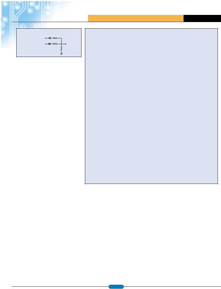
impedance using three resistors and two diodes |
|||||||||||||||||||||||||||
ISR always be entered from the CPU sleep state so |
||||||||||||||||||||||||||||
compute. You can see the current free particle as a |
(see |
Figure |
2). Including the |
diodes |
made |
it |
||||||||||||||||||||||
that the interrupt latency remains the same number |
blur in the lower right corner of the screen. |
|||||||||||||||||||||||||||
easier to figure out the values of the resistors. |
|
|||||||||||||||||||||||||||
of cycles. Normally the AVR interrupt latency varies |
|
|
|
|||||||||||||||||||||||||
To make the pixels almost square, I duplicated them |
Applications |
|
|
|
|
|
|
|
|
|
||||||||||||||||||
by one or two cycles because instructions cannot be |
|
|
|
|
|
|
|
|
|
|||||||||||||||||||
interrupted and are one to three cycles long (most |
vertically onto two lines so that the 100 vertical |
After the sync generation and pixel blasting is |
||||||||||||||||||||||||||
often one cycle). |
|
|
|
|
|
|
|
|
|
|
pixels covered 200 video scan lines. This duplication |
done, the Mega163 still has some cycles leftover. |
||||||||||||||||
|
|
|
|
|
|
|
|
|
|
|
|
also reduced flickering. |
On lines that don’t display the image (lines 231 to |
|||||||||||||||
In the ISR, the horizontal and vertical sync pulses are |
To display an image, you need to compute points, |
262), the CPU is used for about 7 µs for sync |
||||||||||||||||||||||||||
generated and the line counters are updated. All of |
generation; the rest of the 63 µs is available for |
|||||||||||||||||||||||||||
lines, and text to fill the image RAM. I wrote a point |
||||||||||||||||||||||||||||
the |
logic for |
|
counting |
lines, inverting |
the |
general |
computation. The |
number of cycles |
||||||||||||||||||||
|
plotter routine that could set, clear, or invert a pixel |
|||||||||||||||||||||||||||
horizontal sync |
to |
make |
vertical |
sync, |
and |
available |
is |
about |
55 x |
20 x |
8 |
= |
8800 |
|||||||||||||||
given its x, y coordinates. On top of the point routine, |
||||||||||||||||||||||||||||
changing the I/O port pin are contained within the |
(microseconds per |
line |
x |
number |
of |
lines |
x |
|||||||||||||||||||||
I wrote a Breshenham line drawing routine that runs |
||||||||||||||||||||||||||||
5-µs horizontal sync pulse time (see Listing 1). |
|
|
8 cycles per microsecond). I wrote a few simple |
|||||||||||||||||||||||||
|
|
quickly on a small CPU because it requires no |
||||||||||||||||||||||||||
|
|
|
|
|
|
|
|
|
|
|
|
applications |
to |
see |
what |
would |
fit |
into |
||||||||||
|
|
|
|
|
|
|
|
|
|
|
|
divisions, only shifts and adds. [5] I wrote two |
||||||||||||||||
The |
main program |
initializes |
ports, |
timers, |
and |
8800 cycles and not interfere with the image |
||||||||||||||||||||||
character generators, one for 5 x 7 characters and |
||||||||||||||||||||||||||||
static image material, and then goes into a while |
generation. |
|
|
|
|
|
|
|
|
|
|
|||||||||||||||||
one for 3 x 5 characters. The 3 x 5 characters are |
|
|
|
|
|
|
|
|
|
|
||||||||||||||||||
loop. The loop is repeated once per line and includes |
|
|
|
|
|
|
|
|
|
|
|
|
|
|
||||||||||||||
adequate for numbers, but marginal for text. |
To test the image generation, I wrote a command |
|||||||||||||||||||||||||||
an assembler sleep command to suspend execution |
||||||||||||||||||||||||||||
However, the 3 x 5 characters can be drawn quickly |
line |
interpreter that received commands via |
||||||||||||||||||||||||||
until |
the next |
interrupt. You |
may |
download |
a |
|||||||||||||||||||||||
because they’re placed into image memory via a bit |
the |
UART |
from |
Microsoft |
HyperTerminal. |
I |
||||||||||||||||||||||
summary of the program functions from the Circuit |
||||||||||||||||||||||||||||
copy operation and do not use the point drawing |
implemented commands for line, point, and text. |
|||||||||||||||||||||||||||
Cellar ftp site. |
|
|
|
|
|
|
|
|
|
|
||||||||||||||||||
|
|
|
|
|
|
|
|
|
|
routine. The 5 x 7 characters are placed into image |
Also, the entire image could be erased (see Photo 1). |
|||||||||||||||||
|
|
|
|
|
|
|
|
|
|
|
|
|||||||||||||||||
www.atmel.com |
page 9 |
|
A T M E L A P P L I C A T I O N S J O U R N A L
Port D.6 video |
300Ω |
Port D.5 sync |
1kΩ |
To TV |
|
|
75Ω |
Figure 2: During a 0-V sync pulse, both outputs are low. At the black level, the sync output is high. At the white level, the video output is high.
To avoid image degradation from asynchronous UART events, the UART was polled 60 times per second for an incoming character. The command string was built up until a carriage return occurred, and then interpreted during the interval when no image lines were actually being displayed. This program is a prototype for a student lab in which one CPU generates video (the graphics controller) while another connected CPU computes a game, sends graphics commands, and produces sound effects.
I wrote a diffusion-limited aggregation (DLA) program to check the particle dynamics and the image RAM read-back (see Photo 2). A DLA is a structure that grows by sticking new particles to an existing clump. The DLA generally develops a fractal shape as more particles stick to it. In my code, the DLA starts as a single pixel in the center of the screen and grows every time a randomly moving particle happens to hit it. When a particle hits, it is frozen in place, and a new particle appears at the edge of the screen to diffuse. A single particle can easily move 60 random steps per second, including: erasing the old position; computing two random steps (x and y); drawing the new position; checking for adjacent frozen particles; releasing a new particle (if necessary); and updating the clock display once per second. This program is a prototype for a game-type student lab.
To test its performance, I tried to see how many new characters or lines I could draw before the image generation code overran into the image refresh time. I could write four large characters (4 x 35 = 140 pixels written), 40 small characters, or four lines, each one-half the screen width. A complex image can be built up over several frame times, but any animated pieces of the image must be limited to less than about 140 pixels per frame. Recoding the point routine in assembler speeds up
Listing 1— Amusingly enough, the logic to generate 5µs sync pulses exactly fits in about 40 cycles (5 µs); thus the C code is sufficient except for a few lines of code written in assembler.
//The sync generator must be entered from Sleep mode to get accurate timing of the sync pulses. At 8 MHz, all of the sync logic fits in the 5- s sync pulse.
syncON is initialized to zero
syncOFF is initialized to pull bit 5 high: 0b00100000
The tokens "begin" and "end" are used instead of the usual C curly brackets
*/
interrupt [TIM1_COMPA] void t1_cmpA(void) begin
PORTD = syncON; |
//Start the sync pulse |
LineCount ++ ; |
//Update the curent scanline number |
//Begin inverted (vertical) sync after line 247. Inverting sync means reversing the values of syncON and syncOFF.
if (LineCount==248) begin
syncON = 0b00100000; syncOFF = 0;
end
//Back to regular sync after line 250 if (LineCount==251)
begin
syncON = 0;
syncOFF = 0b00100000; end
//Start new frame after line 262
if (LineCount==263) LineCount = 1;
PORTD = syncOFF; //End sync pulse end //ISR
line drawing by about a factor of two; I plan to assign this task as a student lab exercise.
In the Lab
I plan to use this software in an upcoming semester. The performance is good enough for simple games (e.g., Pong or Snake), a clock, a digital voltmeter, or an oscilloscope display. The real-time control of the TV in itself makes a useful learning exercise. I look forward to seeing what kinds of things creative students will do with it. You may download the source code from the Circuit Cellar ftp site or the Cornell web site (instruct1.cit.cornell.edu/courses/ee476/video/inde x.html). 
To download the code, go to ftp.circuitcellar.com/pub/Circuit_ Cellar/2003/150/.
References
[1]P. Stang, “TV Paint,”
Coursework from Stanford University, EE281, Laboratory Assignment no. 4, Handout no. 7 October 2002 www.stanford.edu/class/ee281/handouts/lab4.pdf.
[2]A. Ricci Bitti, “Video DVM,” www.geocities.com/CapeCanaveral/Launchpad/3632/dvm.htm.
[3]G. Williamson, “Television,”
www.williamson-labs.com/480_tv.htm.
[4]R. Gunée, “Software Generated Video,” www.efd.lth.se/%7Ee96rg/mc/mc.html#softvideo.
[5]D. Rodgers, Procedural Elements
of Computer Graphics, 2nd edition, McGraw-Hill, New York, NY, October 1997.
www.atmel.com |
page 10 |
|
A T M E L A P P L I C A T I O N S J O U R N A L
Low-Cost Occupancy Sensor Saves Energy
OCCUPANCY SENSORS CAN SAVE UP TO 80% OF THE LIGHTING AND HVAC ENERGY WHEN PROPERLY APPLIED. MODERN SENSORS, WITH THE AID OF LEADING-EDGE MICROCONTROLLERS, HAVE MANY SOPHISTICATED FEATURES SUCH AS THE ABILITY TO SELF-ADJUST TO OCCUPANCY DATA COLLECTED IN A PRESCRIBED “LEARNING PERIOD”.
By: Markus Levy, Convergence Promotions
Advances in technology make it easier for us to save energy and help our environment. One example where technology has a significant role is in occupancy sensors to control lighting, heating and cooling according to motion detected within an intermittently occupied area. Occupancy sensors can save up to 80% of the lighting and HVAC energy when properly applied. Modern sensors, with the aid of leading-edge microcontrollers, have many sophisticated features such as the ability to self-adjust to occupancy data collected in a prescribed “learning period”. These sensors also reduce false-on and -off conditions. Another useful feature is a “lights-out warning” in the form of an audible or visible (lights flicker) indicator that lights will be turning off in one minute (time should be adjustable).
Defining the Project Goals
To effectively implement an intelligent occupancy sensor, there are several key factors to consider. These factors include a reduced bill of materials, lower power consumption, and reduced time-to- market. Ideally, you should also consider ways to reduce the finished goods inventory.
As with every new generation of products, the most logical evolutionary design step is to determine how to reduce the bill of materials. Continuous advances in semiconductor technology make it possible to
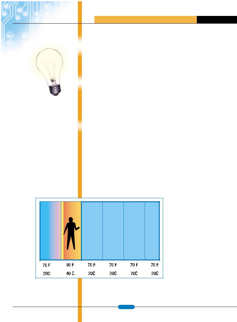
Fig.1: An infrared sensor can be used with the PYRO technique to segment a room and compare the infrared value to a control database stored in flash memory.
shrink chip sizes while simultaneously integrating more features, all at a lower cost. For example, the cost of the electronic components in the occupancy sensor that we’ll be discussing dropped from $6.60 (for the previous generation product) down to $4.00. The biggest cost savings comes from not having to use external analog-to-digital converters (ADC), brown-out detection circuitry, and a crystal. In addition to the cost savings, higher levels of integration also leads to reduced system board size, higher reliability, and typically more functionality of the end product.
Building a Better Sensor
The increased functionality of an occupancy sensor is represented with features such as signature analysis, adaptive time out, adaptive occupancy sensing, and audible and visual alerts. One of the toughest challenges for a motion sensor is to be able to reject unwanted signals such as those caused by pets or wind-based motion of curtains, papers, or plants. In complex surveillance systems this is accomplished using a video camera and a high-performance digital signal processor. On the other hand, in an inexpensive occupancy sensor, movement in a room is captured and processed by an ADC and the resulting conversion is stored in SRAM. When the signature of the room is analyzed, the microcontroller compares this with values stored in a flash memory look-up table.
In addition to using a motion sensor to determine room activity, an infrared sensor combined with an ADC channel scans the room and identifies small changes in the thermal environment. The PYRO technique is one algorithm used in conjunction with the infrared sensor. This technique divides the room into segments and continuously compares the samples of these segments (Figure 1). Another ADC channel measures the ambient light level. Based on information from the I/R sensor, the amount of ambient light will be used to determine if the light switch should be triggered.
An infrared sensor can be used with the PYRO technique to segment a room and compare the infrared value to a control database stored in flash memory. The occupancy sensor can also be fitted with an adaptive time out mechanism to determine when to shut off the switch.
Using the microcontroller’s on-chip real-time clock, the microcontroller can calculate the time out based
www.atmel.com |
page 11 |
|

|
A T M E L A P P L I C A T I O N S J O U R N A L |
on how the space is used. The system can begin |
|
to develop usage patterns and log data every 15 |
|
minutes over the previous week (also known as |
|
learning) to build a database and understand how |
|
the space is used. |
|
Another important feature is the ability to warn |
|
people prior to the switch turning off. (How many |
|
times have you been motionlessly working in a |
|
conference room and the lights automatically turn |
|
off, leaving you in solid darkness?) You can take |
|
advantage of the microcontroller’s PWM channel |
|
and its compare and capture feature, combined |
|
with an external piezo speaker element to |
|
generate different sounds for different user |
|
settings. Alternatively, the system can generate a |
|
warning by flashing the room’s lights on and off. |
|
Additional user feedback can be communicated |
Figure 2: The ATmega88 integrates many useful peripherals to facilitate the design of a cost-effective |
with a flashing LED built into the sensor. This LED |
occupancy sensor. |
|
|
can be connected to the microcontroller’s I/O ports |
|
that can sink or source 20mA without the need for |
|
external circuits or current limiting resistors. The |
|
high boundary mark of 20mA allows a direct |
|
connection of an LED to the AVR microcontroller |
|
without a resistor. |
|
Pulling Out the Stops
The microcontroller that can make this sophisticated occupancy sensor a reality is Atmel’s AVR 8-bit RISC microcontroller called the ATmega88 (Figure 2). This microcontroller integrates a wide variety of peripherals, but the peripherals specifically valuable to the sensor include a very accurate 10-bit ADC with up to 8 differential channels, 8K of self-programming flash, 512 bytes of EEPROM, 1K SRAM, and an internal RC oscillator. This oscillator can go from sleep to wake up and stabilization in 6 cycles, 10x faster than competitive solutions. This fast wake up time has a major impact on power consumption. The ATmega88’s I/O ports with internal pull-up resistors on every pin can be turned on or off individually as required and the timer/counters have compare, capture and PWM outputs.
The Atmega88 integrates many useful peripherals to facilitate the design of a cost-effective occupancy sensor.
The performance of the ATmega88, along with its variety of peripherals allows designers to build one occupancy sensor to serve multiple markets. The microcontroller’s in system Flash program memory enables simplified inventory management, just-in-time delivery, and eliminates wasted product due to code patches. 
www.atmel.com |
page 12 |
|

A T M E L A P P L I C A T I O N S J O U R N A L
TRADITIONALLY, MOST 8-BIT EMBEDDED PROGRAMS HAVE BEEN WRITTEN IN ASSEMBLY LANGUAGE. HOWEVER, DUE TO A VARIETY OF REASONS, MOST NEW MICROCONTROLLERS INCLUDING THE 8-BIT ONES ARE NOW EXPECTED TO HAVE A C COMPILER AVAILABLE. COMPARED TO AN EQUIVALENT ASSEMBLY PROGRAM, A WELL-WRITTEN C PROGRAM IS TYPICALLY MORE READABLE AND MAINTAINABLE. PLUS, WITH SOME CARE AND SOME AMOUNT OF CHANGES, THE C PROGRAM MAY BE MOVED TO OTHER TARGETS. WITH THE MATURITY OF C COMPILER TECHNOLOGIES, AND NEWER CPU ARCHITECTURES THAT ARE MORE SUITABLE FOR HIGH LEVEL LANGUAGE COMPILATION, THE QUALITY OF THE C COMPILER GENERATED CODE FOR THESE NEWER 8-BIT MICROCONTROLLERS CAN BE COMPETITIVE WITH PROGRAMS WRITTEN IN ASSEMBLY LANGUAGE. HOWEVER, SOMETIMES ONE NEEDS TO KNOW THE CHARACTERISTICS AND QUIRKS OF THE ARCHITECTURE AND THE COMPILER ONE IS USING TO ACHIEVE GOOD TO EXCELLENT CODE OPTIMIZATION. IN THIS PAPER, I WILL DESCRIBE SOME OF THE AREAS THAT YOU MAY WANT TO PAY ATTENTION TO REGARDING YOUR SELECTED ARCHITECTURE AND COMPILER.
How to Program an 8-bit Microcontroller Using C language
By: Richard Mann, Imagecraft
IO Registers
A microcontroller has on-chip peripherals that dramatically decrease the amount of external components needed in a design. It may have general purpose IO, serial IO,ADC and sometimes even special purpose IO pins that support protocol such as the I2C bus, all built into the chip itself. Typically these peripherals present themselves as IO registers to the CPU – for example, to generate a high signal on an output pin, one usually only requires the CPU to write a “1” to the corresponding IO register bits.
Some CPU architectures have a separate IO space for these registers with special instructions to access them. Since there is no such concept as IO space in the C language per se, in these cases the C compiler provides an extension allowing access to these IO registers. For example, you may have seen something like
unsigned char porta @port 0x3B;
The “@port <address>” is an extension that presumably declares an IO port with name “porta” at location 0x3B. Another popular way to declare something similar is:
ººSFR porta = 0x3B;
In this example, “SFR” (probably standing for Special Function Register) is used to declare “porta” at the same address. Since extensions are defined by the compiler vendors, the syntax and semantics vary among different compilers, even for the same microcontroller target. As they are not part of Standard C, certain behaviors may be not well defined. For example, the compiler may or may not allow you to declare a pointer to these objects (sometimes this is disallowed because the target machine disallows indirect accesses to the IO registers).
Since they are not standard C objects, the compiler may also restrict which C operators you can use on them, and tone should consult the compiler manual to see whether a particular C operator is allowed.
Memory Pointers
Some CPU architectures put these IO registers in regular data space. Some, like the Atmel AVR, even allow you to address the IO registers using either special IO
instructions or by treating them as data memory. In this case, something like the following works well:
#define PORTA |
(*(volatile |
unsigned char *)0x3B) |
|
… |
|
unsigned char i = PORTA; // |
|
read |
|
… |
|
PORTA = i; |
// write |
|
|
The #define expression casts location 0x3B as a pointer to an unsigned char and then dereferences it, allowing the expression to be used to both read and write to the address. The “volatile” qualifier tells the compiler that the object at this location may change, so that compiler should always perform an actual read or write to the location and not use any previously cached values. If a CPU architecture allows you to access the IO registers as memory addresses, then you can treat them exactly like any other memory pointers. This allows you to perform the full range of C operations on the objects.
Accessing Bits
One often needs to access individual bits of an IO register. For example, PORT A may be an 8-bit output register, and each bit of the IO register corresponds to a hardware output pin of the PORT. There are several methods of accessing bits in C, with advantages and disadvantages to each approach:
Bitwise Operations
Plain C is powerful enough to perform any needed bit operations on IO registers (or any other integer objects). (After all, one of the first major tasks for the original C compiler was to rewrite the nascent Unix operating system in C!) Note the following bitwise operation example:
#define PORTA |
(*(volatile |
unsigned char *)0x3B) |
|
#define BIT(x) |
(1 << (x)) |
// bit position |
|
… |
|
PORTA |= BIT(0); |
// |
turn on 0th bit |
|
PORTA &= ~BIT(0); |
// turn off |
0th bit |
|
PORTA ^= BIT(0); |
// |
toggle the 0th bit |
|
|
|
www.atmel.com |
page 13 |
|

A T M E L A P P L I C A T I O N S J O U R N A L
if (PORTA & BIT(0))// test to see if 0th bit is set
…
This approach is probably the best overall: it works on all compilers, it defines the bit position explicitly and without ambiguity, and it will often result in optimal code sequences from the compilers. A minor inconvenience is that the usage seems more awkward than using bitfield names (as described below), but this can be alleviated by using C preprocessor macros; for example:
compared to bitwise operations. Lastly, according to the C Standard, only “unsigned (int)” and “int” are acceptable datatypes for a bitfield member. Some compilers allow “unsigned char”, but it is an extension. Whether or not a compiler allocates only a byte for the above structure depends on the particular compiler. If a compiler uses two bytes for the above structure, then using this method of accessing bits will not work. Due to these reasons, this approach is not really recommended for bitwise accessing of IO registers.
#define SETBIT(p, b) |= BIT(b)
#define CLRBIT(p, b) &= ~BIT(b)
etc.
Bitfields in a C Struct
(p)A similar situation applies to multi-byte registers such as the Atmel AVR ADC register pair. It consists of a
high and low data register that have
(p)consecutive addresses, but which need to be accessed in certain order. Make sure the compiler does this properly, or if you roll your own code, make sure YOU do it properly.
C allows you to declare bitfields within a structure, such as:
typedef struct { |
|
unsigned |
bit0 : 1, |
|
bit1 : 1, |
|
bit2 : 1, |
|
bit3 : 1, |
|
bit4 : 1, |
|
bit5 : 1, |
|
bit6 : 1, |
|
bit7 : 1} |
IOREG;
#define PORTA(*(IOREG *)0x3B)
…
int i = PORTA.bit0;// read
…
PORTA.bit0 = i; // write
Again, we see that it is more convenient if the CPU allows IO registers to be treated as data memory. Casting the IO location (0x3B in this example) to the appropriate structure type is no different from casting it as a pointer to a byte. If you must use an extension such as “@port” or “SFR”, as shown earlier, you may or may not be able to declare bitfield structures and use them as described.
This is seemingly a nice way to map the IO register bits to the C language. However, a potential problem exists: the C Standard does not define the bitfield allocation order, and the compiler may allocate bitfields either from right to left or from left to right. If you use this method, you should make sure to consult the compiler manual to ensure that your use of the bit ordering matches the compiler’s usage. It is also possible that some compilers may generate more verbose code for bitfield operations as
IO Port Bit Extension
Some compilers that provide the IO register syntax extension (e.g. “SFR” declaration) may further provide an extension to specify the bit position of a named IO register. For example:
SFR PORTA = 0x3B; |
|
… |
|
i = PORTA.0; |
// read the |
0th bit |
|
PORTA.0 = 1; // set the bit
…
etc.
In other words, the operator “.<digit>”, which is an extension to Standard C, allows you to access the bit denoted by the digit. Unlike structure bitfield,the bit position is explicit and unambiguous. However, since this is an extension and since a good solution already exists using standard C bitwise operations, this method is not recommended.
Const Qualifier and Strings in Harvard Architecture
If you have read-only tables or “variables”, then you should declare them with the “const” modifier. In most cases, the compiler will allocate them in the program memory and not take away precious SRAM space. Some microcontrollers have what is known as the "Harvard Architecture" – the program and data spaces are separate and different instructions are needed to access items in the separate spaces. The normal semantic of C literal strings (e.g.“strings”) is that they must behave like arrays in data space. Consider the case with the string function strcpy: You should be able to call the function with the second argument being either a literal string or an array in RAM. However, using this takes up valuable
RAM space. To lessen the use of the precious SRAM, some compilers for Harvard Architecture targets allow you to make strings allocatable in the program space, However, selecting this option means that you will probably need to call different functions depending on whether the argument is a literal string or an array in the data space.
Global Variables or Local Variables?
In theory, the choice of whether to declare a variable as a global or local variable should be dictated by how it is used. If the variable is accessed by multiple functions spread across different files, then they should be declared as global variables,e.g. declared outside of any function definitions. If a variable is used only within a function, then it should be declared inside the function as a local variable.
To further limit the visibility of the variable name and thus improve program readability, if a global variable is accessed only by the functions within a single file, you can prefix the variable declaration with the storage class “static”to make it visible to that file only. When a variable is only used with a statement block (inside a function) but its value must be retained across multiple invocations of the function, then you should declare the variable with the “static” storage class in the statement block where it is used. (This helps to further limit name visibility.) Despite the differences in syntax, file-static and func- tion-static variable still behave like global variables and are treated as such. Some 8-bit systems have separate memory spaces, e.g. 8051 has internal and external data space. This may limit how you declare and use global variables.
If a variable is only used within a statement block and does not need to retain its value across multiple function invocations, then it is declared with the "auto" storage class in the statement block where it is used. The auto storage class is the default storage class for any variable declared inside a statement block, so you may omit it, or you may explicitly use the keyword “auto” to specify the storage class. The keyword “register” has the same meaning as “auto”, except that you are providing a hint to the compiler that it should try to allocate this variable to a CPU register (although the compiler is free to ignore the hint), and you will not be taking the address of a register variable. The compiler allocates storage for global variables at program link time, and therefore each global variable has a unique address in the SRAM. The instructions that access global variables typically encode the addresses as part of the instructions. Since an address is usually 16 bits long in an 8-bit
www.atmel.com |
page 14 |
|

A T M E L A P P L I C A T I O N S J O U R N A L
microcontroller, each global variable address takes up to 2 bytes in the instruction. Some CPU architectures allow a short form of addressing, using only one byte to encode a global variable address if it fits certain conditions.
The usage patterns of local variables mirror a stack: as the function becomes active, the function’s local variables become active as well. Once the function exits, the function’s local variables can be destroyed. If the target architecture provides support for a stack, then the compiler will probably use the stack for allocation of the local variables. A nice feature of the stack is that the maximum amount of memory used for local variable allocation is usually less than the total number of local variables in the program, since stack space is reclaimed once a function exits. Unfortunately, some popular 8-bit microcontrollers do not support a stack or support only a limited version of a stack. In those cases, the compiler typically examines the usage patterns of the local variables and allocates them statically (possibly assigning some of them to the same addresses), simulating the natural effect performed by the stack.
If your chosen microcontroller does not directly support a stack, then you should merely declare your variables in the usual way and not worry about optimizing their usage. However, if your chosen CPU architecture does support a stack, then you may wish to examine how your compiler generates code for global and local variables, and see whether there are benefits in favoring one type of variable over the other, because of the CPU instruction set and memory. Note that this sort of optimization should not be undertaken casually, since for program readability variables should be declared in a manner consistent with their use.
As a test, you can use this simple program:
void main(void)
{
…
a = b + c;
}
Declare the three operands as global variables and then as local variables, and note the differences in the sizes of the resulting code. If the target architecture supports short and long forms of global variables, declare them as such and see the differences produced there too. If you are declaring them as local variables, you may have to initialize them, possibly using a function call.
Otherwise, an optimizing compiler may eliminate some or all operations:
int foo(int); main()
{
int a, b = foo(2), c = foo(3);
a = b + c; foo(a);
// uses “a” so the compiler will not optimize it away
}
int foo(int x) { return x; }
With an aggressive compiler, the above program may still be optimized away, but chances are that it will produce usable results for most compilers.
It is best to look at the compiler-generated listing and not just at the total memory usage from a map file, as there will be extra code that the compiler puts in to make your program into a complete executable program. Most CPU architectures will use more instruction space to access global variables. How much more depends on the architecture and the compiler. If the code bloat associated with using global variables is acceptable to you, then by all means do not attempt to optimize their usage.
Sometimes it is even possible to save code space by using global variables; for example, as an alternative to passing parameters between functions (which can be expensive under some CPU architectures). This is a fairly controversial subject. If you go with this route, be sure to observe good software engineering practices, e.g. give the variables good descriptive names, limit and localize their accesses, etc.
So, what can you do to reduce the overhead of using global variables? You might rewrite your code so that global variables are not used. You should look at the resulting program to make sure that you do not add code bloat elsewhere, since you may have to change your program algorithmically. Another possibility is that you can cache global variable accesses:
{
extern int global_i; int i = global_i;
…
// read/write using “i” instead of “global_i”
…
global_i = i;
}
This only works if any updated values of “global_i” are not needed in an interrupt handler or something similar while this function is executing. Before making this change, you should check how your compiler handles multiple appearances of the same global variable in a function. Some compilers may perform similar caching of the global variables as in the example above, saving you from doing it manually. Some compilers may also cache a pointer to the global variable, which may still be a win under some architectures, and this technique allows asynchronous concurrent access of the global variable in an interrupt handler.
Register Promotion Optimizations
Most of the earlier microcontrollers have few registers; some as little as a single accumulator. Some of the newer microcontrollers have more registers. For example, the Atmel AVR has 32 8-bit registers, and all of the AVR arithmetic and logical instructions will only work on register operands. Even if a microcontroller can operate on memory operands, it often still pays to keep the operands in registers since they take up less instruction space.
The C storage class “register” is meant to be a hint to the compiler that the variable should be allocated to a CPU register if possible, instead of in the default stack location. Fortunately, most modern compilers now take care of this automatically by performing register allocation optimization, and the “register” keyword is usually not necessary. Again, consult your compiler manual to see whether this is done automatically or not.
The quality of the register allocation varies as well, depending on the compiler and the specific architecture. The more general the register set, the easier it is for good register optimizations. Here are some register related optimizations that a compiler may perform, beyond the automatic promotion of certain variables into registers:
1.Lifetime Analysis – an optimization that determines the beginning and end of the variable usage. This analysis must handle loops and other control structures in the programs. Using this information, further optimizations can be performed.
2.Lifetime Splitting – using the lifetime analysis information, the compiler may “split” a variable into multiple pseudo-variables, each with distinct lifetimes.
www.atmel.com |
page 15 |
|

A T M E L A P P L I C A T I O N S J O U R N A L
3. Register Allocation – using lifetime information, the compiler can pack the variables into registers more intelligently. For example, it may pack multiple variables into a single register if their lifetimes do not overlap. Or if it has performed lifetime splitting, then each distinct lifetime may get its own register.
The more registers available to the compiler, the better it can do register allocation. Compilers that do lifetime splitting, for example, can allow the compiler to allocate the split pseudo-variables into different registers, or perhaps put only some of them in registers, depending on the situation. If your compiler does not perform lifetime splitting, then declaring the variables in the smallest enclosing statement block and using distinct variables for different uses will help the compiler to do a better job.
Some compilers allow you to declare global registers, thus allowing you to assign a certain number of global variables to registers. This is especially useful if your program uses a lot of interrupt handlers. Normally, if you write an interrupt handler in C (via some sort of extension since Standard C has no syntax for declaring interrupt handlers), then the compiler must save and restore any registers the handler uses, so that the state of the machine is restored when the handler exits. If there are a lot of interrupts or interrupt handlers, it can be costly in both instruction size and the speed of the program. Using global registers solves this problem.
Choose Your Data Types Carefully
An advantage of using C over assembly language is the data type handling – you simply declare variables of the needed types, and the compiler takes care of storage allocation and code generation. However, if you are looking to optimize your program, you need to be careful what data types you use for your variables. Standard C does not dictate the sizes of the integer data types except that the following size relationship holds, and that “int” is at least 16-bits:
sizeof (char) <= sizeof (short) <= sizeof (int) <= sizeof (long)
In practice, for most 8-bit C compilers,“char” is 8-bits, “short” and “int” are 16-bits, and “long” is 32-bits.
Using the “unsigned” type may possibly improve your code size, as some CPU architectures favor the use of unsigned types. For example, it may be cheaper to zero-extend a byte than sign-extend a byte into an integer word. Moreover, dividing an
unsigned integer by a power of 2 can be done as a logical right shift, but a signed integer divide cannot be done by arithmetic right shifts without additional compensating code.
You should avoid using “long” or floating point variables unless necessary, because most - if not all - 8 (and even 16-bit) microcontrollers do not support these operations directly. In fact, most 8-bit microcontrollers do not support 16-bit operations at all. Using long data types in an expression will probably increase the code size and the running time of the code by at least a factor of two to four compared to using “int” data types, depending on which C operations you use.
Standard C provides two floating point data types: float and double (long double was introduced to the standard in C99). Most C compilers provide at least the 32-bit “float” data type, usually conforming to various degrees to the IEEE754 standard. The C Standard dictates that the “double” data type be at least 64-bits, but some compilers opt to make “double” 32-bits, since the need for 64-bit floating point is very rare on an 8-bit microcontroller.
Using floating point operations will dramatically increase the code size and execution speed of your program. In fact, some people argue that floating point should not be used unless necessary in the 8-bit microcontroller world because of the size and speed penalty and the intrinsic imprecise nature of the floating point operations. For example, in this simple program:
float f = 3.1;
f -= 1.0;
if (f == 2.1) do_something();
The comparison may not execute as true since floating point computation depends on the implementation. Any implementation must compromise on either the range or the precision of the floating point computations. For the purpose of optimization and perhaps even for the purpose of a better fit to your task, you may wish to investigate using alternatives to floating point. Sometimes one can use plain integers, and sometimes one has to use scaled integers. Unfortunately, since scaled integers and other similar alternatives are not in Standard C, any such use would either be provided by the compiler as an extension, as library functions, or as a roll-your-own solution.
Overhead of Library Functions
One word: printf. While it is expected that the compiler provide a printf function, a full implementation supporting all the features can eat up a lot of program memory. There are a lot of esoteric features in printf, plus a full implementation drags in all the floating point support functions. Most compilers provide you the option of selecting different versions of printf, each with varying capabilities and code size requirement. Choose the one that closest matches your needs. If your program space or SRAM space is really tight, you may perhaps even forgo printf and use the simpler conversion functions such as itoa(), ltoa(), and ftoa() if your compiler provides them.
Conclusion
Since the cost of an embedded system is magnified by the number of units shipped, embedded engineers need to juggle between the cheapest possible chips, development cost, and the time-to- market. Well-written C helps to give you a leg up on the competition when working on the next version of your product, as C allows more control over "almost-always-not-enough" scarce resources. Hopefully, attention to and understanding of the issues brought up in this paper will assist in your 8-bit microcontroller C programming endeavors. 
Stay informed! Subscribe NOW to The Atmel Applications Journal. www.atmel.com/ journal/mail.asp
www.atmel.com |
page 16 |
|

A T M E L A P P L I C A T I O N S J O U R N A L
IT’S JUNE, AND DAVID IS HEADING TO THE BEACH. SCUBA DIVERS TYPICALLY CHART THEIR DIVE DATA THE OLD-FASHIONED WAY, WITH PENCIL AND PAPER. BUT, ENGINEERS ALWAYS LOOK FOR A CHALLENGE, RIGHT? COMBINING HIS TALENTS, DAVID DEVISED A SUBMERSIBLE DATA LOGGER THAT UPLOADS TO A PC.
Reprinted with permission of:
Circuit Cellar
Issue 131
June, 2001
Under the Sea
Designing a SCUBA Dive Monitor with the AVR AT90S4433
By: David Smith
Hobbies often produce the inspiration for some of the most interesting projects. This project is the result of the cross-pollination of my interest in embedded systems and love of SCUBA diving. It’s important to mention that SCUBA has inherent risks, however, these risks may be minimized with proper training from any one of the major certifying agencies. With that said, let’s begin at the end — the completion of a dive.
Following a dive, it is customary practice to log it. This typically consists of recording the maximum depth reached, elapsed dive time, air consumed, water temperature, and post-dive pressure group (a diving concept that is beyond the scope of this article) in a logbook. Often I wanted to record more specific information. That’s when the idea of d esigning a diving data logger, which I dubbed the DiveMate (see Photos 1, 2, and 3), began to take form.
I planned to create a logger that records depth and temperature measurements every few seconds and allows the data to be uploaded to a PC following the dive. The data then may be plotted versus time, resulting in a concise, easily interpreted chart. Then, this chart can be printed and placed in the logbook along with the rest of the information, providing a detailed record of the dive.
Specifications
Like many projects, the specifications for the DiveMate evolved during development. Originally, the main requirements were to be able to measure and display the current depth and temperature and store periodic measurements of these quantities for retrieval following the dive(s).
Photo 1: The initial DiveMate prototype is ready for action. This is a top view with the cover closed.
These broad requirements were subsequently refined into mode specifications.
The DiveMate has four main modes: Surface Interval, Dive, Communication, and Shutdown. During Surface Interval mode, the DiveMate counts and displays the amount of time elapsed since it was powered up or since the last dive, whichever is more recent. From this state, the DiveMate transitions to Communication mode if it receives a communication request via the serial port. Transition to Communication mode must occur within less than 1 second of receipt of the request.
Surface Interval mode transitions to Dive mode if the DiveMate measures a depth of greater than 5 feet. The test for this transition must be made no less frequently than every 10 seconds to avoid missing more than a few seconds of data at the beginning of the dive. This trade-off allows the DiveMate to operate at reduced power during Surface Interval mode by requiring only that the pressure sensor (depth measurement device) be powered for a short instant during the 10-s interval. The device enters Shutdown mode if a given period of time elapses without entering Dive mode.
During Communication mode, the DiveMate operates as a slave device to a master RS-232 serial host (i.e., desktop computer), which initiates all communication. The host performs configuration of the device and queries it for information. Shutdown mode is initiated if no communication occurs for 5 minutes. or if the immediate shutdown command is issued via the serial port.
In Dive mode, the DiveMate measures, stores, and displays depth and temperature every 2 and 10 seconds, respectively. In order to time stamp this data as it’s stored, a means for keeping time, even during shutdown, is required. Because divers may go on extended trips, the DiveMate must be able to store up to five days worth of data at approximately 3 hours of diving per day. The transition to Surface Interval mode occurs when the device reaches a depth of 5 feet. or shallower.
Shutdown mode may not be exciting, but it’s essential. When entering Shutdown mode, the DiveMate powers down its hardware to save battery life. From Shutdown mode, the device transitions to Surface Interval mode during powerup.
www.atmel.com |
page 17 |
|

A T M E L A P P L I C A T I O N S J O U R N A L
The electronics must be housed in a waterproof enclosure capable of withstanding more than five atmospheres, or 74 psi, of pressure. This is the approximate pressure experienced at the maximum recreational dive limit of 130 feet. Furthermore, the pressure sensor must be exposed to external water pressure without allowing the enclosure to flood. Similarly, the temperature sensor must be exposed to the external water temperature via an interface with a low thermal time constant in order to prevent a delay in the accurate measurement of the water temperature. Finally, the enclosure must allow a contained display to be visible.
Details
The heart of the DiveMate is the extremely versatile, 8-bit Atmel AVR microcontroller. The AVR AT90S4433 is a 28-pin RISC device with 4 Kb of flash memory for code storage, 128 bytes of SRAM for user data, and 256 bytes of EEPROM also for user data. One important detail to note is that the AVR’s instruction word size is 16 bits, meaning that it can hold at most 2000 assembled instructions.
A nice feature of this micro’s flash memory-based program is that it is (off-line) in-system programmable. This means no more tedious burn-and-turn gymnastics with the EPROM programmer and UV light source. The ’4433 has 32 general-purpose registers, a UART, SPI port, 10-bit ADC, 8-bit counter, 16-bit counter, watchdog timer, and on-chip analog comparator.
The microcontroller uses a Harvard bus architecture (separate instruction and data buses), and executes the majority of its instructions in a single clock cycle. This provides up to 8 MIPS at a maximum 8-MHz clock frequency. The ’4433 also features a linear address space with no address paging required. Additionally, it has a full-featured, vectored interrupt controller like the ones typically seen on higher-end microcontrollers. [1] For a solid introduction to the Atmel AVR microcontroller, read “Working with AVR Microcontrollers,” by Stuart Ball (Circuit Cellar 127).
For the DiveMate to function as specified, it must be capable of accurately measuring depth. Because the pressure of the surrounding water is proportional to depth, a submersible pressure sensor with a maximum pressure rating of at least 74 psi is required for operation to 130 feet.
An investigation of the available sensor options led to the conclusion that there are two main
Photo 2: With the cover open, the prototype’s layout and components are easily observed.
alternatives. The first class of sensors includes signal conditioning on-chip and produces a calibrated, temperature-compensated output proportional to the detected pressure. The second alternative is a class of uncompensated sensors that typically requires biasing via a constant current
Photo 3: The view of the bottom shows the pressure sensor and its interface to the outside world.
source as well as external temperature compensation. As is usually the case, the compensated sensor is simpler to use, but more expensive than an uncompensated sensor. Within the two larger classifications, there are three subclassifications—differential, gauge, and absolute. A differential sensor is typically a two-port device that allows separate pressures to be applied to each port, resulting in an output that is proportional to the difference between the input pressures. A gauge sensor appears to be a one-port device, however, it is little more than a differential sensor in which the missing port is replaced by an opening exposed to ambient pressure. An absolute sensor is a true one-port device. It produces an output that is proportional to the difference between the input pressure and an on-chip vacuum cavity, which provides an absolute reference.
After examining the silicon pressure sensors available, I chose the MPX5700GP. This compensated
sensor has a maximum operating pressure of 101.5 psi, sensitivity of 44.14 mV/psi, accuracy of 2.5% of full scale output, and a full scale output span of 4.5 V. The sensor requires a 5-V power supply. Additionally, it contains a fluorosilicone gel that provides protection for the sensor die from the environment. [2] The gauge configuration was chosen mostly because of availability and smaller package size. As with pressure, a dedicated sensor is required for temperature measurements. Some temperature sensing alternatives include thermistor circuits, semiconductor analog sensors, and digital temperature sensors. The first two options require calibration and analog-to-digital conversion via the microcontroller’s onboard ADC. Although this is feasible, the third option offers a simpler alternative that is less susceptible to noise and requires virtually no calibration.
The DiveMate employs the Dallas Semiconductor DS1621 direct-to-digital temperature sensor for three reasons. The DS1621’s very low 1-µA standby current is a boon for battery-powered applications. The 8-pin device communicates with the AVR via a two-wire bus interface (equivalent to the I2C protocol) which it shares with two yet-to-be- discussed components. The DS1621’s accuracy is 0.5°C over a –20° to 105° range, which is more than adequate for this application. [3] But, if you want more accuracy, the aforementioned analog sensor option is the best choice.
In order to provide time and date stamps for the data, the DiveMate includes a Dallas DS1307 real-time clock. This 8-pin chip uses an external 32.768-kHz crystal and maintains accurate time and date information even when turned off. It interfaces with the AVR via the same two-wire bus as the temperature sensor. The chip features 56 bytes of nonvolatile RAM, although the DiveMate doesn’t use it. [4]
An Atmel AT24C256 serial EEPROM is included to provide 32Kb of nonvolatile data storage. This IC is rated at one million write cycles with a 100-year data retention rating. Similarly to the temperature sensor and real-time clock, this EEPROM interfaces with the AVR via the two-wire bus. Judicious choice of data structures allows a single EEPROM chip to store the specified number of dives (five days, 3 feet per day) at the desired measurement intervals (2-s depth, 10-s temperature). If you need greater storage, up to four Atmel AT24C256 chips could be located on the two-wire bus to provide up to 128 Kb of data storage. [5]
www.atmel.com |
page 18 |
|