


terminators are inserted in unused jacks at the far end of the segment. For small hubless systems this approach is attractive.
Glass Fiber Optics—Duplex glass, multimode fiber optic cable uses either SMA or ST™ connectors and is available in three sizes measured in microns: 50/125, 62.5/125 and 100/140. Larger core sizes launch more energy allowing longer distances. The industry appears to have selected 62.5/125 as the preferred size. This core size, operating with 850 nm transceivers, provides long distances, reasonable cost, immunity to electrical noise, lightning protection and data security. Glass fiber optic cable is used in hazardous areas and interbuilding cabling on campus installations or whenever metallic connections are undesirable. Connectors can be either SMAs or STs. The STs look like a small BNC and are more tolerant to abuse than SMA. ST connectors have become more popular than the traditional SMA connector.
For very long distances up to 14 km, single mode fiber optics operating at 1300 nm is recommended. Cable attenuation is much less at 1300 nm than at 850 nm.
DC Coupled EIA-485—One popular cabling standard in industrial installations is EIA-485. A single twisted-pair supports several nodes over a limited distance. Screw terminal connections or twin RJ-11 jacks are provided so that the modules can be wired in a “daisychain” fashion. EIA-485 offers a hubless solution, but with limited distance and low common mode breakdown voltage.
AC Coupled EIA-485—The EIA-485 transformer coupled option provides the convenience of EIA-485 connectivity, but with a much higher common mode breakdown voltage. Distances and node count are reduced from the DC coupled EIA-485 option. The AC coupled option is insensitive to phase reversal of the single twisted-pair that connects the various nodes but may not operate over the full range of data rates of the newer ARCNET controllers.
Cable Once the topology and transceiver are specified, the cable can be selected. There are basically three choices in cabling: coaxial, twisted-pair and fiber optic. Each type has its advantages and when using active hubs all three types of cabling can be mixed within one network—an example of ARCNET’s extreme flexibility.
Coaxial Cable—RG-62u was the original choice for cabling ARCNET systems, and is recommended over RG-59/u if possible. RG-62/u (93 ohm) is a better impedance match to the coaxial transceiver and has less attenuation than RG-59/u (75 ohm) yielding greater distances. Standard BNC connectors and tees are
9
www.ccontrols.com

used. Coaxial cable is relatively inexpensive and provides the highest propagation factor compared to other alternatives.
Twisted-Pair—Unshielded twisted-pair cabling can be used with several transceivers including those for EIA-485. We recommend IBM type 3 (although other unshielded twisted-pair cable with similar characteristics will also work). Twisted-pair cable is inexpensive and convenient to use and easy to terminate. However, twisted-pair cable has much greater attenuation than coaxial cable and, therefore, has limited distance capability.
Fiber Optics—Fiber offers the greatest distance but requires more attention to its application. There are many varieties of cables and cable pairs. The use of 62.5/125 duplex cable for conventional installations and single mode for long distances is suggested.
For indoor applications tight buffering is recommended and for outdoor applications loose buffering is recommended. Study the attenuation figures for the specified fiber to ensure that it is within the available power budget. Fiber optics can span the greatest distance, but has a lower propagation factor than coaxial cable. It may be necessary to calculate the resulting signal delay to ensure it is within ARCNET limits.
Electrical Code
Cable installations must comply with both federal and local ordinances. Plenum-rated (within air distribution systems) and riser-rated (between floors) cables are available, but at a higher cost, to meet the requirements of the National Electric Code (NEC). Consult the relevant documents for applicability when installing an ARCNET network.
Coaxial Cable Offers Good
Price/Performance
The original ARCNET specification called for RG-62/u coaxial cable as the medium between hubs and NIMs. With the desire to eliminate hubs, the bus transceiver was developed but RG-62/u coaxial cable remained as the specified cable. Therefore, there are two transceivers: coaxial star for distributed star systems and coaxial bus for hubless systems.
P1, P2 Signaling
All ARCNET controller chips develop two signals called P1 and P2 that drive the coaxial transceiver (sometimes referred to as the hybrid). Both P1 and P2 are negative true signals of 100 nanoseconds in duration with P2 immediately following P1 when operating at the default 2.5 Mbps data rate. These signals occur when an ARCNET controller transmits a logic “1.” If a logic “0” is
10
www.ccontrols.com
to be transmitted, no pulses are sent and the line remains idle. The sum of P1 and P2 is 200 nanoseconds; however, one signaling interval of ARCNET requires 400 nanoseconds. The remaining 200 nanoseconds are absent of signaling. A center-tapped transformer is wired to two drivers connected to P1 and P2. When P1 is received by the transceiver, the coaxial cable is driven in a positive direction for the duration of the pulse. When P2 is received by the transceiver, the coaxial cable is driven in a negative direction for the duration of the pulse. The resulting signal is called a dipulse that approximates a single sine wave. Since this all occurs over a 200 nanosecond interval, the waveshape appears as a 5 Mhz signal instead of 2.5 Mhz which is what we would expect with ARCNET. Therefore, cable attenuation calculations should be made at 5 Mhz instead of 2.5 Mhz. Since the dipulse has no DC component, transformer operation is simplified.
Star vs. Bus
The coaxial star transceiver and the coaxial bus transceiver both receive P1 and P2 signals and generate dipulse signals. However, the star transceiver represents a low impedance (approximately 93 ohms) at all times while the bus transceiver represents a high impedance when idle allowing for multiple transceivers to be attached to a common bus. Since the two transceivers have a similar appearance, it is important to distinguish one from another. The following practice is recommended for identification purposes. For star transceivers, use black bodied BNC connectors on the printed-circuit board. For bus transceivers, use white.
The capabilities of the two transceivers differ significantly. The star transceiver can drive 2000 feet (610 m) of RG-62/u cable while the bus can only drive 1000 feet (305 m). However, the bus transceiver can support eight nodes on a single segment. Connections between nodes are made with BNC tee connectors and coaxial cables of at least six feet (2 m) in length. Passive termination is required at the ends of bus segments. The isolation of the two transceivers is typically 1000 volts DC.
Twisted-Pair—Inexpensive
and simple to use
Twisted-pair is also a popular cabling technology. It is inexpensive and easy to terminate. However, it has much higher attenuation than coaxial cable limiting its use to shorter distances. Frequently, modular jacks and plugs are used to interconnect segments. Twisted-pair cable can be used with conventional coaxial star transceivers if a BALUN is used between the cable and the transceiver. A MUX LAB 10070 is recommended for use as an external BALUN. It has a male BNC connector at one end and a RJ11 jack at the other, and it must be used only with coaxial star
11
www.ccontrols.com

Modular Connector Pin Assignments
4-Contacts |
6-Contacts |
8-Contacts |
|||
Pin |
Usage |
Pin |
Usage |
Pin |
Usage |
1 |
|
1 |
|
1 |
|
2 |
LINE- |
2 |
|
2 |
|
3 |
LINE+ |
3 |
LINE- |
3 |
|
4 |
|
4 |
LINE+ |
4 |
LINE- |
|
|
5 |
|
5 |
LINE+ |
|
|
6 |
|
6 |
|
|
|
|
|
7 |
|
|
|
|
|
8 |
|
12
transceivers. For convenience, some vendors provide a product that eliminates the need for external BALUNs. The twisted-pair star transceiver incorporates an internal BALUN along with a coaxial star transceiver together as one unit. Simply connect to the provided RJ-11 jack. When using BALUNs, only star and distributed star topologies are supported. No phase reversal of the wiring is allowed. Many modular plug patch cables invert the wiring. To test for this, hold both ends of the cable side by side with the retaining clips facing the same direction. The color of the wire in the rightmost position of each plug must be the same if there is no inversion of the cable. If this is not the case, the cable is inverted.
Twisted-Pair Bus
For hubless systems, twisted-pair bus transceivers can be used. Since modular jacks are used and a bus connection is required, two jacks, internally wired together, are provided on each NIM.
Field connections are then made in a daisy-chain fashion to each successive NIM. The remaining end jacks are then plugged with passive terminators. A modular plug terminator is available for this use. Each daisy-chain cable must not invert the signals and must be at least six feet long for reliable operation.
Hubs can be used to extend twisted-pair bus segments. Use a twisted-pair star hub port in place of the passive terminator at one end of the segment. Connect this last port on the NIM to the twisted-pair star port on the hub using an “inverted” modular plug cable. This is necessary since the BALUN in the twisted-pair star port creates a signal inversion that is not compatible with the twisted-pair bus port. The interconnecting inverted cable “rights” the signal. Connect the second twisted-pair bus segment in a similar fashion using an additional twisted-pair star port.
Data Rate Selection
Conventional ARCNET NIMs communicate only at a 2.5 Mbps rate. Newer generation COM20019, COM20020, COM20022, COM20051 ARCNET controllers have a prescaler that allows communication at other speeds. Although lower data rates facilitate longer bus segments, variable speed hub electronics are required to service these rates. Of course, for hubless systems this is not a problem. Data rates down to 19 kbps are possible with the 20019 controller and as high as 10 Mbps with the 20022. Do not change the data rate on systems with dipulse transceivers since the transceiver is tuned to 2.5 Mbps and can only operate at that data rate.
Backplane Mode
The COM20019, COM20020, COM20022, COM20051 ARCNET controller family offers additional interfaces not available in earlier
www.ccontrols.com
EIA-485—A popular industrial standard
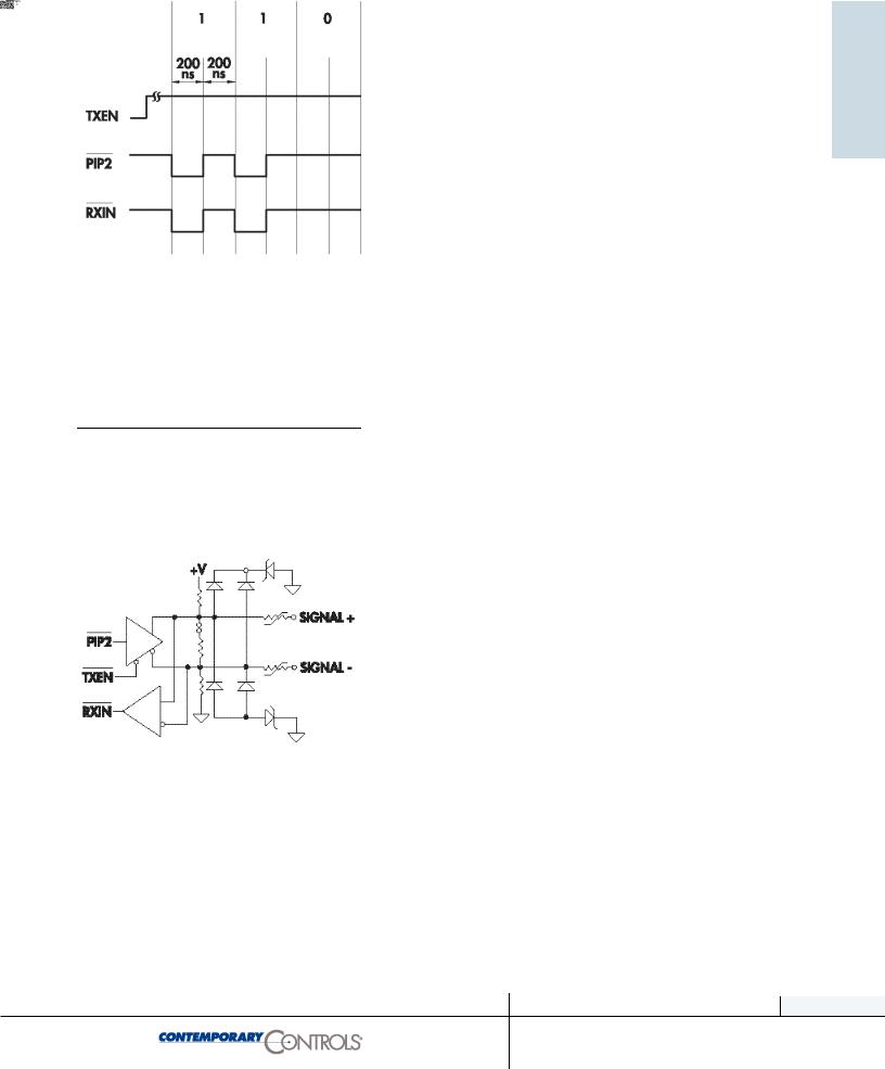
generation controllers. Upon power up, the chips default to conventional ARCNET mode where P1 and P2 signals are generated to develop the required dipulse signal. However, if backplane mode is programmed into these chips, the P1 signal is stretched into a 200-nanosecond signal and P2 becomes a clock. The sense of the receiver pin (RXin) is inverted so that it may be tied directly to the negative true P1. In the simplest configuration, the P1 and RXin pins of all the controllers that are to communicate to one another are tied together using a single pull-up resistor. The bus segment must remain extremely short limiting this configuration to applications of several nodes communicating within one instrument. However, the distances can be extended significantly if driver and receiver electronics are inserted between the P1 signal and RXin. A logical choice would be EIA-485 due to the popularity of the standard. To implement a party line EIA-485 requires one additional signal called TXEN that is generated by the newer chips. This signal is ignored in conventional dipulse mode and unavailable on earlier ARCNET controllers.
EIA-485 standard supports multimaster operation and is, therefore, suitable for use with ARCNET in either backplane or nonbackplane modes. Non-backplane mode implementations require an extended P1 signal and the generation of TXEN. Two EIA-485 implementations are supported on ARCNET, DC-coupled and ACcoupled. The capabilities of each approach are different.
DC Coupled 485
The original EIA-485 specification deals with the problem of data transmission over a balanced transmission line in a party-line configuration. With ARCNET, any node can transmit; therefore, multiple drivers and receivers share a common twisted-pair cable. EIA-485 does not specify a data link protocol and, therefore, a means must be provided that ensures only one driver has access to the medium at any one time. ARCNET provides its own medium access control (MAC), and it is used to successfully implement the EIA-485 network.
Standard Microsystems Corporation has made recommendations on how to implement EIA-485 with ARCNET. They studied reflections, signal attenuation and DC loading. Since EIA-485 does not specify a modulation method or cabling, rules need to be developed for ARCNET based EIA-485 networks.
In order to reduce reflections, it is necessary to terminate the cable in its characteristic impedance. Since the driver can be located anywhere along the network, a terminator must be supplied at
13
www.ccontrol.com

both ends of the cable. It is recommended that unshielded or shielded twisted-pair cable with characteristic impedance of 100 to 120 ohms be used. Therefore, matching terminators must reside at each end of the segment.
Only one driver is enabled at any one time in an operating network; however, there are times when no drivers are operational causing the twisted-pair cable to float. Noise and reflections along the line can cause the various receivers to incorrectly detect data creating data errors. These receivers need to be biased into their “off” state to ensure reliable operation. Decreasing the bias resistance improves immunity to reflections but can load the drivers excessively. Also, the amount of bias required increases with the number of receivers on the line. Since differential receivers are used, both pull-up and pull-down resistors are required to properly bias the receivers. Through experimentation, SMSC recommends an optimal biasing resistor of 810 ohms. It is recommended that this resistance be distributed over two modules—each located at the ends of a segment in order to simplify the cabling rules. The modules at the ends of the segment will be strapped for biasing resistors and a line terminator while all other modules will have
no biasing or termination. Since two modules are being used to supply bias, their resistors will be increased to 1600 ohms. With this approach, a total of 17 nodes can share a single segment up to 900 feet (274 m) in length.
Although differential line drivers and receivers are used, this fact does not remove the need for a common ground among all the nodes. A cold water pipe connection is a possibility. The common mode voltage experienced by any one node should not exceed +/- 7 volts. A good grounding system would ensure that this requirement is met.
AC Coupled EIA-485
One method to achieve a much higher common mode rating is to transformer couple the EIA-485 connection. SMSC has developed such an approach achieving a common mode rating of 1000 volts DC. This implementation does not require biasing resistors, as does the DC coupled approach; however, line terminators must still be applied at each end of the cable segment. The AC coupled EIA-485 approach has the additional advantage that connections to each node are insensitive to phase reversal. This is because the symbol on the cable reverses polarity on successive logic “1”s. Polarity of the wiring need not be observed. However, this implementation is rated at 13 nodes maximum over 700 feet (213 m) of cable.
14
www.ccontrols.com

Extending bus segments beyond the 700 or 900 foot (213–274 m) limit is possible with the introduction of active hubs.
AC coupled design may not operate over all data rates so the vendor specifications should be studied.
Termination
A benefit of using active hubs is that no passive-termination is required at each port nor must unused ports be terminated. Only bus segments of either coaxial or twisted-pair cabling require termination. Termination for twisted-pair cable includes EIA-485. In general, passive termination equal to the characteristic impedance of the cable needs to be applied at each end of the bus segment. If one end of the bus segment attaches to a port on an active hub, no termination is required at that end.
For RG-62/u cable, use a 93 ohm terminator attached to a BNC tee connector. For twisted-pair cable, use a matching terminator that plugs into the unused RJ-11 connector at each end of the bus segment. If no RJ-11 connector exists, use a discrete resistor attached to screw terminals or with some NIMs—an onboard terminator can be invoked by inserting a jumper.
Applying Fiber Optics to Achieve a Robust Design
The use of fiber optics in LANs, such as ARCNET, has increased due to the inherent advantages of using fiber. High data rates can be maintained without electromagnetic or radio frequency interference (EMI/RFI). Longer distances can be achieved over that of copper wiring. For the industrial/commercial user, fiber offers high-voltage isolation, intrinsic safety and elimination of ground loops in geographically large installations. ARCNET will function with no difficulty over fiber optics as long as some simple rules are followed.
There are varying types of fiber optic cabling, but basically the larger size fiber (in diameters of 50, 62.5 and 100 microns for conventional installations) is recommended. With this size fiber, multimode operation will be experienced requiring the use of graded index fiber. Transceivers operating at 850 nm wavelength offer a good performance/cost tradeoff.
A duplex cable is required since each fiber optic port consists of a separate receiver and transmitter which must be cross-connected to the separate receiver and transmitter at the distant end. Only star and distributed star topologies are supported.
15
www.ccontrols.com

Optical Power Budget (25°C)
Fiber Size
(microns) |
850 nm-dBm |
1300 nm-dBm |
Single mode |
N/A |
13.0 |
50/125 |
6.6 |
21.0 |
62.5/125 |
10.4 |
22.0 |
100/140 |
15.9 |
N/A |
200/230PCS |
9.4 |
N/A |
For distances beyond 3 km, single mode fiber optics used with 1300 nm transceivers is recommended. With this approach, segment lengths up to 14 Km can be realized.
Optical Power Budget
When specifying a fiber optic installation, attention must be paid to the available optical power budget. The power budget is the ratio of the light source strength to the light receiver sensitivity expressed in dB. This value must be compared to the link loss budget that is based upon the optical cable and optical connectors. The link loss budget must be less than the power budget. The difference is called the power margin which provides an indication of system robustness.
Minimum Transmitter Output Power (25°C)
|
|
Fiber Size |
NA |
Xmit Power |
Xmit Power |
|
|
|
|
(microns) |
(Numerical) |
850 nm-dBm |
1300 nm-dBm |
||
|
|
|
Aperture) |
|
|
|
|
|
|
Single mode |
N/A |
N/A |
-22.0 |
|
|
|
|
50/125 |
0.200 |
-18.8 |
-14.0 |
|
|
|
|
62.5/125 |
0.275 |
-15.0 |
-13.0 |
|
|
|
|
100/140 |
0.300 |
-9.5 |
N/A |
|
|
|
|
200/230PCS |
0.400 |
-16.0 |
N/A |
|
|
|
|
|
|
|
|
|
|
|
Minimum Receiver Sensitivities (25°C) |
|
|
|
|||
|
Fiber Size |
Sensitivity |
Sensitivity |
|
|||
|
(microns) |
850 nm-dBm |
1300 nm-dBm |
||||
|
Single mode |
N/A |
|
-35.0 |
|
|
|
|
50/125 |
-25.4 |
|
-35.0 |
|
|
|
|
62.5/125 |
-25.4 |
|
-35.0 |
|
|
|
|
100/140 |
-25.4 |
|
-35.0 |
|
|
|
|
200/230 PCS |
-25.4 |
|
N/A |
|
||
Transmitter power is typically measured at one meter of cable and, therefore, includes the loss due to at least one connector. The outputs vary so each device should be tested to ensure that a minimum output power is achieved. The output power also varies with core sizes. In general, larger cores launch more energy.
Receiver sensitivity also varies so tests should be run to determine the least sensitive receiver. The difference between the weakest transmitter and least sensitive receiver is the worst case power budget that should be specified. Realized power budgets will exceed this value since the probability of the worst case transmitter being matched with the worst case receiver is remote. However, it is recommended to use the stated power budgets for each core size.
Link Loss Budget
The cable manufacturer usually specifies the fiber optic cable attenuation for different wavelengths of operation. Use this figure to determine the maximum distance of the fiber link. It is necessary to include losses due to cable terminations. Connectors usually create a loss of from 0.5 to 1 dB. For example, assume a 1500 meter run of 62.5 cable that the manufacturer specifies as having an attenuation of 3.5 dB per 1000 meters. The cable loss will be 5.25 dB. Assuming two connector losses of 0.5 dB each, the link loss budget would be 6.25 dB which is within the 10.4 dB power budget specified. The 5.15 dB difference represents a high degree of margin. A 3 dB margin is what is typically recommended.
Overdrive
Overdrive occurs when too little fiber optic cable is used resulting in insufficient attenuation. To correct this condition, a jumper is typically removed in each fiber optic transceiver to reduce the gain
16
www.ccontrols.com

Calculating Permissible
Segment Lengths
sufficiently to allow for a zero length of fiber optic cable to be installed between a transmitter and receiver. This is potentially a problem with 100 micron cable.
A segment is defined as any portion of the complete ARCNET cabling system isolated by one or more hub ports. On a hubless or bus system, the complete ARCNET cabling system consists of only one segment with several nodes, however, a system with hubs has potentially many segments. An ARCNET node is defined as a device with an active ARCNET controller chip requiring an ARCNET device address. Active and passive hubs do not utilize ARCNET addresses and, therefore, are not nodes. Each segment generally supports one or more nodes but in the case of hub-to-hub connections, there is the possibility that no node exists on that segment.
The permissible cable length of a segment depends upon the transceiver used and the type of cable installed. The following table provides guidance on determining the constraints on cabling distances as well as the number of nodes allowed per bus segment.
The maximum segment distances were based upon nominal cable attenuation figures and worst case transceiver power budgets. Assumptions were noted.
When approaching the maximum limits, a link loss budget calculation is recommended.
When calculating the maximum number of nodes on a bus segment, do not count the hub ports that terminate the bus segment as nodes. However, do consider the maximum length of the bus segment to include the cable attached to the hub ports.
Several bus transceivers require a minimum distance between nodes. Adhere to this minimum since unreliable operation can occur.
ARCNET’s data link protocol is fully described in ANSI/ATA 878.1
17
www.ccontrols.com