

книги / FISMA and the risk management framework the new practice of federal cyber security
..pdfMechanical analysis of the scratching properties of coated polymers |
17 |
flow stress |
~ to Young's modulus E, thermal effects were neglected and a, |
was equal to 0. |
|||||
Eq. (7) then becomes: |
|
|
|
|
|
|
|
|
m |
h |
2 |
|
(}"y=k i~ |
|
|
|
|
which implies |
(8) |
||||
|
(j =k Bvp(! gBvp |
||||||
The three |
parameters, k, /lg and m have |
been described |
previously |
[15] |
and were |
||
determined by an inverse method adapted to large deformations and based on interpretation of the force-penetration curves in indentation tests with two indenter shapes: m = 0.078 and hg =
4.5. In our case, the strain rate was higher than in [I 5] and the consistency was adjusted: k = 87 MPa.s·m. Figure 12 compares the experimental compressive stress-strain data with the numerical function used for the present simulations. In the case of perfectly elastic-plastic behaviour, this contact model has been validated for coated and uncoated materials [38] by comparing it with all well known elastic solutions [35-37].
-co a..
-~c.
E
8
b
Q)
::I.._
I-
400r---------.-~~---.----.---~
350 |
|
|
|
•. |
|
|
|
|
|
300 |
-• |
modelled law |
|
• |
|
.:• |
|||
250 |
|
~// |
• |
|
200 |
|
|
||
|
|
|
|
|
150 |
r |
|
|
|
50 |
|
|
|
|
100 |
|
"*"""'"". |
|
|
|
.......... |
|
|
|
|
|
|
|
|
0~-------- |
.--- |
~---.--------- |
4 |
|
0.0 |
0.2 |
0.4 |
0.6 |
|
True strain
Fig. 12. Comparison of the stress-strain function used for the present simulations with the experimental data
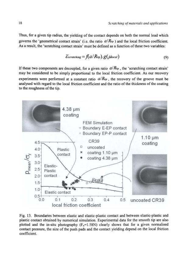
Numerical simulations were performed to locate the boundaries between elastic and elasticplastic contact and between elastic-plastic and plastic contact. The first boundary could be simply related to the first finite volume having a strain higher than the elastic strain, while the second was defined to occur when all the matter contained in the half spherical volume under the contact area flowed plastically. These two boundaries appear in Figure 13, where the normalised contact pressure is plotted against the local friction coefficient. The results obtained for the first boundary agree with those reported by Johnson [35]. Experimental data for the smooth tip are plotted on the same figure and the in-situ photographs clearly show that for a given normalised contact pressure, the size of the push pads and the contact yielding depend on the local friction coefficient.

Mechanical analysis of the scratching properties of coated polYmers |
19 |
Recovery ofthe groove
It was not easy to measure the radius of the groove section just after contact, at the beginning of the life span of the groove. Although the contact displayed yielding, if the unloading after contact was elastic and hence reversible, a second passage of the scratching tip along the groove
with a section of concave radius Ro did not increase the yielding. The following analysis may be considered to transfer to scratching the results of previous work on indentation [35]. Provided the elastic sliding may be predicted with the elastic Hertz theory, the radius of the groove can be related to the radius of the tip through the equation:
1 |
1 |
3Fn |
(10) |
Ro |
l?r;p |
4E*a3 |
where E* is the Hertz contact elastic modulus. During recovery, the edges of the groove lie parallel. The mean strain in the matter around the groove may be defined as:
(II)
and the recovery of the groove is described by the ratio:
c(t) _ Ro c;- R(t)
(12)
This recovery is plotted in Figure 14. During contact, the recovery process was not freely stressed because contact between the tip and the surface existed. The start of recovery was defined to occur after contact, i.e. after the maximum strain had been imposed at the maximum
contact width for a time to :
(13)
Results are in agreement with the previous analysis. A comparison of the two curves for the uncoated material indicates that the recovery increases if the tip is smooth, which is related to the fact that the local interfacial strain decreases if there are no micro scratches. A comparison of the two curves for the rough tip indicates that the recovery increases if the sample has been coated. This is linked to a decrease in the yield in the elastic-plastic strain under the contact area as the local friction coefficient decreases.

20 |
Scratching of materials and applications |
rough tip - CR39
rough tip - coating 1.1 !Jm smooth tip - CR39
0 ·1 |
|
rto=a!Vtip |
|
|
|
|
|
|
|
I |
|
|
|
|
|
0.01 |
0.1 |
10 |
100 |
1000 |
10000 |
||
|
|
|
life time (min) |
|
|
|
|
Fig. 14. Recovery of the groove left on the surface as a function of time. The recovery increases if the tip is smooth or if the local friction coefficient is low (coated sample).
CONCLUSIONS
Deposition of a scratch-resistant coating is a common way to improve the scratch behaviour of a polymeric surface. However, a thin scratch-resistant coating cannot prevent yielding on the macroscopic scale of the contact. In-situ photographs show macro grooves with parallel edges, which is an indication of the occurrence of yielding during contact. The mechanical behaviour of a coating on a viscoelastic material is easily described by considering the normalised contact pressure and should be analysed in terms of the shape of the stress field, modified by the effect of the local friction between a scratching tip and the surface, where this local friction will depend on the roughness of the tip and the presence of the coating. A coating decreases the yielding in the elastic-plastic behaviour of the contact if the local friction coefficient between the surface and the tip is low. The major benefit is the reduction of the "scratching contact strain".
The ratio of the thickness of the coating to the roughness of the tip is confirmed to be a critical parameter, which enables one to increase the scratch resistance in the case of a thin coating.
The recovery of the groove left on the surface must be analysed in relation to the contact behaviour. If the local friction coefficient is low and there are no micro scratches along the macro groove, the recovery may be fast.
REFERENCES
I.Demirci, I., Gauthier, C. and Schirrer R. (2005) Thin Solid Films 479, 207
2.Bucaille, J.L., Felder, E., Hochstetter, G. (2004), Journal ofTribology 126, 372.
3.Lawn, B.R., (1967), Proceeding ofthe Royal Society London Ser. A 299,307.
4. |
Velkamp, J.D.B., Hattu, N., Snijders, V.A.C., In: Fracture Mechanics of Ceramics Vol. |
|
3: Cracks formation during scratching of brittle materials, pp273-301 Ed. R.C. Bradt, |
|
D.H.P. Hasselman and F.F. Lange, Plenum Press, N.Y. (1978). |
5. |
Malzbender, J., de With, G., (2000), Surface and Coatings Technology 135, 60. |
Mechanical analysis of the scratching properties ofcoated polymers |
21 |
6.Steinmann, P.A., Tardy, Y., Hintermann, H.E., (1987), Thin Solid Films 154, 333.
7.Burnett, P., Rickerby, D.S., (1987), Thin Solid Films 154,403.
8.Bull, S.J., Rickerby, D.S., Matthews, A., Legland, A., Pau, A.R., Valli, J., (1988),
Surface and Coatings Technology 36, 503.
9.Thouless, M.D., (1998), Engineering Fracture Mechanics 61, 75.
10.Malzbender, J., de With, G., (2002), Surface and Coatings Technology 154,21.
11.Blees, M.H., Winkelman, G.B., Balkenende, A.R., Den Toonder, J.M.J., (2000), Thin Solid Films 359, 1.
12.Bertrand-Lambotte, P., Loubet, J.L., Verpy, C., Pavan, P., (2002), Thin Solid Films 420421, 281.
13.Briscoe, B.J., Thomas, P.S., (1995), Tribology Transactions 38, 382.
14.Gauthier, C., Schirrer, R., (2000), Journal ofMaterials Science 35, 2121.
15.Gauthier, C., Lafaye, S., Schirrer, R., (2001), Tribo/ogy International34, 469.
16.Tabor, D., (1970), Review ofPhysics in Technology 1, 145.
17.Briscoe, B.J., Sinha, S.K., (2003), Materialwissenschaft und Werkstofftechnik 34, 989.
18.Zhang, S.L., Nishizoe, K., (2004), Tribology Letters 16, 73.
19.Jardret, V., Morel, P., (2003), Progress in Organics Coatings 48, 322.
20.Wong, J.S.S., Sue, H.J., Zeng, K.Y., Li, R.K.Y., Mai, Y.W., (2004), Acta Materialia 52, 431.
21.Darlix, B., Montmittonnet, P., Monasse, B., (1986), Polymer Testing 6, 189.
22.Syed Asif, S.A., Pethica, J.B., (1998), Journal Adhesion 61, 153.
23.Basire, C., Fretigny, C., (1997), CR. Acad. Sci. t. 325, Serie II b, 211.
24.Lee, E.H., Radok, J.R.M., (1960), Journal ofApplied Mechanics 27, 438.
25.Hill, R., (1992), Proceedings ofthe Royal Society Math. and Phys. Sci. 436, 617.
26.Ting, T.C.T., (1966), Journal ofApplied Mechanics Trans ASME, 35,845.
27.Graham, G.A.C., (1967), International Journal ofEngineering Sciences 5, 495.
28.Yue, Z.Y., Eggeler, G., Stockhert, B., (2001), Computational Materials Science 21, 37.
29.Karapanagiotis, I., Evans, D.F., Gerberich, W.W., (2002), Polymer 43, 1343.
30.Shen, W., Smith, S.M., Ye, H., Jonnes, F., Jacobs, P. B., (1998), Tribology Letters 5, 75.
31.Krupicka, A., Johansson, B., Johansson, M., Hult, A., (2003), Progress in Organic Coatings 48, 14.
32.Bucaille, J.L., Gauthier, C., Felder, E., Schirrer, R., (2005), Wear in press doi: l 0.1 016/j.wear.2005.04.007
33.G'Sell, C., Jonas, J.J., (1979), Journal ofMaterials Science 14, 583.
34.Gauthier, C., Schirrer, R., The viscoelastic viscoplastic behaviour of a scratch on a polymeric surface, Proceedings ofthe 2nd World Tribology Congress WTC2001, Vienna Austria September 2001, CDRom, ISBN 3-901657-09-6
35.Johnson, K.L., Contact Mechanics. Cambridge University Press, 1985.
36.O'Sullivan, T.C., King, R.B., (1988),Journal ofTribology llO, 235.
37.Hamilton, G.M., Goodman, L.E., (1966), ASME Journal ofApplied Mechanics 33, 371.
38.Demirci, I. Phd, Louis Pasteur UniversityULP Strasbourg France, 2004.
39.Lafaye, S., Gauthier, C., Schirrer, R., (2005), Tribology International38, 113.
22
CHAPTER2
MECHANICAL ANALYSIS OF THE SCRATCHING OF METALS AND POLYMERS
AT MODERATE AND LARGE STRAINS
Originally published in Tribology International vol 39. February 2006
E. FELDER and J. L. BUCAILLE
Centre de Mise en Forme des Materiaux (CEMEF) UMR 7635 CNRS-Eco/e des Mines de Paris
BP 207 F 06904 Sophia Antipolis Cedex (France). E-mail: Eric.Felder@ensmpjr
ABSTRACT
Scratch test provides a convenient means to study the surface mechanical properties and the tribological performances of materials. The representative strain of the material in this test increases with the attack angle l3 of the indenter and so, for a conical indenter, the strain increases as its apical angle 28 decreases. But the mechanical analysis of this test by analytic models is very intricate. First we perform a preliminary discussion of the various aspects of the problem by considering the plane strain scratching of materials by wedges. Second, we present the conditions of the numerical simulations of the scratch test with conical indenters with a three-dimensional (3D) finite element code. These simulations provide the scratch geometry (contact surface, elastic recovery), the plastic strain map and the volume average plastic strain, the scratch hardness and the force ratio, the apparent friction coefficient ~0=F/W. We compare the behaviour of polymeric and metallic materials in scratch test at low and large strain and relate their difference in scratch resistance to their rheological properties. Polymers develop higher elastic strains at yielding than metals, a phenomenon which is characterised by the yield stress to Young's modulus ratio, f:e = cryiE. For 8=70.3 deg where pure ploughing occurs for all materials, we study the scratching of elastic-perfectly plastic solids with various values of f:e under zero friction. Some comparisons with the behaviour in indentation are performed and we study the influence of friction in the scratching of workhardened steel with the same cone. At high strain the main rheological difference is the workhardening behaviour: it is described by a power law for metals and an exponential law for polymers. For 8 decreasing from 70.3 to 20 deg we compare the behaviour of a cold-worked steel to the behavour of polycarbonate, a thermoplastic polymer: a transition from ploughing to ploughing-cutting occurs only for steel.
KEYWORDS
Scratch, metals, polymers, cone, representative strain, hardness.
Mechanical analysis of the scratching of metals and polymers at moderate and large strains |
23 |
LIST OF NOTATIONS
ar |
frontal contact radius |
a, |
lateral contact radius |
A |
area of the contact surface projected on the sample surface |
b |
width of the residual groove |
c |
shape ratio (he/h) |
E |
Young's modulus |
Ft |
tangential force |
h |
penetration depth |
he |
(lateral) contact depth |
hrc |
frontal contact depth |
hg |
strain hardening coefficient |
H |
indentation hardness |
Hs |
(true) scratch hardness (WIA) |
Hsl/2 |
apparent scratch hardness (8W/[1tb2]) |
m |
strain rate coefficient |
p |
contact pressure |
Vscratch speed
Wnormal force
Xindentation index ([Eicry]cot8)
(Ox,y,z) rectangular coordinate system (at the cone tip)
Oy |
axis parallel to the scratch speed |
Oz |
axis normal to the material surface |
Greek symbols |
|
a |
rear contact angle |
13 |
wedge attack angle |
E |
strain |
i |
strain rate |
Ee |
elastic strain at the yield stress in tensile testing (cryiE) |
Ev |
volume average deformation |
£generalized (plastic) strain rate
£generalized (plastic) strain
Jl |
(true) Coulomb friction coefficient (at the indenter/material interface) (t/p) |
Jlo |
apparent friction coefficient (F1/W) |
28 |
apical angle of the conical indenter |
cry |
yield stress |
cro |
flow stress |
cr 1 |
strength coefficient |
t |
friction shear stress |

24 Scratching ofmaterials and applications
INTRODUCTION
The scratch test is a very old experimental procedure used to study the mechanical properties of materials near their surface. As early as 1722 Reaumur [1] developed a scratch scale which was a measure of the position on an end quenched steel bar which could be scratched by the metal specimen. Exactly a century later (1822) Mohs proposed ten minerals in increasing order of scratch hardness: each mineral will scratch the one on the scale below it but will not scratch the one above it. Another century later (1954) Tabor [2] demonstrates that a metal surface of (indentation) hardness H1 will be scratched by a point of hardness H2 ifH2 ~ 1.2 H1 and that each Mohs standard is approximately 60 % harder than the preceding one. The Tabor's study demonstrates clearly the connections between the (indentation) hardness H and the scratch hardness Hs, a problem related to the the models of contact and friction between solids [3], but the accurate relations are still not well understood even for metals [4,5]. Another problem related to the scratch test is the transition between ploughing (or rubbing) and cutting first investigated to our knowledge by Mulhearn and Samuels [6]. A main parameter for this problem is the attack angle which is defined in Fig.1; they state precisely by experiments the existence of a critical attack angle 13c below which ploughing occurs without any material removal and above which cutting occurs with the formation of a chip. This very complex problem is in context with the matter balance during the scratch test and the understanding of the abrasive machining and the wear of materials [7]. Finally, scratch tests have been applied to polymers in the last 10 years [8- 13] because polymers coatings are often used to increase the scratch resistance in many applications: paintings for automobile industry or optical devices. Because of the large elastic recovery of polymers and their complex rheological behaviour, the analysis and the interpretation of this test is far more difficult than for metals. For example, to compute scratch hardness H., Briscoe eta!. [8] have considered that for all scratch conditions (scratch speed V, angle of the indenter 9) the elastic recovery is complete at the rear face of the indenter (Fig. 1); by building a new apparatus to observe the real contact surface under load Gauthier and Schirrer [13] demonstrated that in fact the contact surface at the rear part decreases as the attack angle 13 increases.
|
A |
,•.. |
|
|
side view |
|
|
front view |
|
|
|
||
under load r~NI |
|
|
|
|||
|
|
____./I |
|
|
|
|
|
|
|
l |
|
|
|
|
|
b |
|
|
|
|
I |
___ /\ |
/'·'-- |
j_ll_; |
; |
---· ·--;/·',\_ Ibr |
|
·j |
tb, |
l |
/ |
li,rf |
||
residual groove |
|
|
|
~--- |
I |
|
\
\__
Fig. I. Geometrical and mechanical parameters during a scratch test performed with a conical indenter with apical angle 29.
Mechanical analysis of the scratching of metals and polymers at moderate and large strains |
25 |
The scratch hardness and the surface defonnation mechanisms of materials depend in particular on the rheology of the material, the indenter geometry and the friction at the interface. But the mechanical analysis of this test by analytic models is very intricate and requires many simplifying assumptions especially in three dimensional (3D) conditions [5, 14-17]. First, after having defined our notations we perfonn a preliminary discussion of the various aspects of the problem by considering the two dimensional (2D) case: the plane strain scratching of materials by wedges. After, we present the conditions of the numerical simulations of scratching with conical indenters with a three-dimensional (3D) finite element code. So we compare the behaviour of polymeric and metallic materials in the scratch test at low and high strain and relate their difference in scratch resistance to their rheological properties. In addition, we discuss the reliability of many assumptions commonly used in the interpretation of the scratch test and compare the indentation and scratch testing.
PRELIMINARY: THE SCRATCHING WITH CONICAL INDENTERS
Representative Strain and Indentation Index
In scratch test, as in indentation, the nonnal component of the material displacement Uz is of the order of magnitude of the penetration depth h and this displacement is accommodated on a distance in relation with the contact radius a=bc/2 (Fig. 1). So the order of magnitude of the strain in indentation Ei or scratching Es is:
(1)
Thus the strain increases with the attack angle 13 or as the semiapical angle e decreases. However, we must notice that the representative strain depends on the investigated problem (indentation or scratching, hardness or volume average value... ) and its relation with cote can be rather complex as we shall demonstrate later. For example for metal indentation, following the Tabor's model of indentation pressure with spherical indenter [18], Johnson proposed that the indentation hardness of metals is related to the value of the flow stress cro at the strain 0.2 cote [19]:
H = Ccr0 (0.2cotB) |
(2) |
So, a first rheological parameter of interest is the yield stress cry to the Young's modulus E ratio:
(3)
Ee defines the order of magnitude of the elastic strain of the material at the point of plastic yielding which is same as the elastic recovery after plastic strain: it is generally very small for metals (0.1-0.5 %) whereas it is much higher for polymers (1-10 %). We may say that the elasticity of the material increases if Ee increases; rigid plastic materials correspond to the limit case Ee =0. If the flow stress of the material does not depend on the strain or the strain rate, case which corresponds to perfectly plastic materials for which the flow stress is always equal to the
26 |
Scratching of materials and applications |
yield stress cro= cry, the behaviour in cone indentation or scratch test at constant temperature is characterised by Ei to Ee ratio, a quantity which we call the indentation index X:
&· |
E |
(4) |
X= _I_= -cotB |
||
&e |
a y |
|
We can expect that the elastic effects become more and more negligible as X increases. For example, for a given value of e, in indentation, the constrain factor C (relation (2)) increases steadily with X and tends toward a limit which depends only one (full plastic regime) C3 (9), C3 (9) being an increasing function ofe under zero friction [19]. Following the approach of Hill et. al. [20] for indentation, we define a quantity which characterises the contact geometry: the shape ratio (Fig. 1):
(5)
For elastic contact (very low X) the contact conditions are described by the Hertz's theory: the contact is limited by a full circle, with the radius a=(2ht)h tanS (the material sinks in), c=2ht-0.637. We expect that as in indentation (see below) c is an increasing function of the indentation index.
Scratch Hardness and Representative Strain
On the indenter are applied a normal force W and a tangential force Ft (Fig. 1). Consider the area of the true contact surface projected on the sample surface A and the width b of the residual groove which is the distance between the tops of the shoulders or the scratch pileups (Fig. 1). We can define two types of scratch hardness related to the normal force:
H |
=w |
8W |
(6) |
|
HS1!2 =--2 |
||||
s |
A |
|
||
|
|
Jrb |
|
Hs is the average contact pressure if friction between material and indenter is negligible; we name Hs the (true) scratch hardness. The quantity Hs112 defined in [4] is easily measured in experiments. Hsr/2-Hs if bc-b and if the contact is restricted on the frontal part and limited by half of a circle (so this requires particularly hc-hrc)· So we name H,w the apparent scratch hardness. If it is assumed in addition that the contact pressure is uniform, the force ratio or apparent friction coefficient flo is related to the apical angle (Fig. 1) [3]:
F, |
2 |
(7) |
flo=-= -cotB (fl = 0) |
||
w |
Jr |
|
This relation is in good agreement with the experimental results of lubricated scratching of metals for 30~9~70 deg [4]. These assumptions on contact geometry are commonly valid for metals because Ee is very small. So the elastic effects are assumed negligible and the contact is considered as restricted to the frontal part [4]. They are not verified for polymers [13]. If, on the