

- •Foreword
- •Preface
- •Acknowledgments
- •Contents
- •Contributors
- •1.2 Forehead Augmentation
- •1.2.1 Discussion
- •1.3.1 Discussion
- •1.4 Rhinoplasty
- •1.4.1 Discussion
- •1.5 Lip Augmentation
- •1.5.1 Discussion
- •1.6 Chin and Jaw Augmentation
- •1.6.1 Discussion
- •Further Reading
- •Forehead Augmentation
- •Rhinoplasty
- •Lip Augmentation
- •Jaw Augmentation
- •2: Imaging the Postoperative Orbit
- •2.1 Eyelid Weights
- •2.1.1 Discussion
- •2.2 Palpebral Springs
- •2.2.1 Discussion
- •2.3.1 Discussion
- •2.4.1 Discussion
- •2.5.1 Discussion
- •2.6.1 Discussion
- •2.7 Strabismus Surgery
- •2.7.1 Discussion
- •2.8 Glaucoma Surgery
- •2.8.1 Discussion
- •2.9 Scleral Buckles
- •2.9.1 Discussion
- •2.10 Keratoprostheses
- •2.10.1 Discussion
- •2.11 Intraocular Lens Implants
- •2.11.1 Discussion
- •2.12 Surgical Aphakia
- •2.12.1 Discussion
- •2.13 Pneumatic Retinopexy
- •2.13.1 Discussion
- •2.14 Intraocular Silicone Oil
- •2.14.1 Discussion
- •2.15.1 Discussion
- •2.16 Orbital Tissue Expanders
- •2.16.1 Discussion
- •2.17 Orbital Exenteration
- •2.17.1 Discussion
- •2.18.1 Discussion
- •Further Reading
- •Eyelid Weights
- •Palpebral Spring
- •Frontalis Suspension Ptosis Repair
- •Strabismus Surgery
- •Glaucoma Surgery
- •Scleral Buckles
- •Keratoprostheses
- •Intraocular Lens Implants
- •Surgical Aphakia
- •Pneumatic Retinopexy
- •Intraocular Silicone Oil
- •Orbital Tissue Expanders
- •Orbital Exenteration
- •3.1.1 Discussion
- •3.2 Septoplasty
- •3.2.1 Discussion
- •3.3.1 Discussion
- •3.4.1 Discussion
- •3.5 Nasal Packing Material
- •3.5.1 Discussion
- •3.6 Rhinectomy
- •3.6.1 Discussion
- •3.7 Sinus Lift Procedure
- •3.7.1 Discussion
- •3.8 Caldwell-Luc Procedure
- •3.8.1 Discussion
- •3.9 External Ethmoidectomy
- •3.9.1 Discussion
- •3.10.1 Discussion
- •3.11 FESS Complications
- •3.11.1 Discussion
- •3.11.2 Discussion
- •3.11.3 Discussion
- •3.11.4 Discussion
- •3.11.5 Discussion
- •3.11.6 Discussion
- •3.11.7 Discussion
- •3.11.8 Discussion
- •3.11.9 Discussion
- •3.11.10 Discussion
- •3.11.11 Discussion
- •3.12 Osteoplastic Flap with Frontal Sinus Obliteration
- •3.12.1 Discussion
- •3.13 Frontal Sinus Cranialization
- •3.13.1 Discussion
- •3.14 Paranasal Sinus Stents
- •3.14.1 Discussion
- •3.15 Frontal Sinus Trephination
- •3.15.1 Discussion
- •3.16.1 Discussion
- •3.17.1 Discussion
- •3.18 Maxillary Swing
- •3.18.1 Discussion
- •Further Reading
- •Septoplasty
- •Nasal Septal Button Prosthesis
- •Nasal Packing Material
- •Rhinectomy
- •Sinus Lift
- •Caldwell-Luc Procedure
- •External Ethmoidectomy
- •Functional Endoscopic Sinus Surgery
- •FESS Complications
- •Osteoplastic Flap with Frontal Sinus Obliteration
- •Frontal Sinus Cranialization
- •Paranasal Sinus Stents
- •Frontal Sinus Trephination
- •Maxillectomy and Palatectomy
- •Maxillary Swing
- •4.1 Occipital Nerve Stimulator
- •4.1.1 Discussion
- •4.2 Tissue Expander
- •4.2.1 Discussion
- •4.3 Temporal Fossa Implants
- •4.3.1 Discussion
- •4.4.1 Discussion
- •4.5.1 Discussion
- •4.6.1 Discussion
- •4.7 Scalp Tumor Recurrence
- •4.7.1 Discussion
- •4.8 Burr Holes
- •4.8.1 Discussion
- •4.9 Craniotomy
- •4.9.1 Discussion
- •4.10 Cranioplasty
- •4.10.1 Discussion
- •4.11 Autocranioplasty
- •4.11.1 Discussion
- •4.12.1 Discussion
- •4.14.1 Discussion
- •4.15 Box Osteotomy
- •4.16.1 Discussion
- •4.17.1 Discussion
- •4.18.1 Discussion
- •4.19 Subdural Drainage Catheters
- •4.19.1 Discussion
- •4.20.1 Tension Pneumocephalus
- •4.20.5 Pseudomeningoceles
- •4.20.6 Pseudoaneurysm
- •4.20.7 Postoperative Infection
- •4.20.8 Textiloma
- •4.20.9 Sunken Skin Flap Syndrome
- •4.20.10 External Brain Herniation
- •4.20.11 Bone Flap Resorption
- •Further Reading
- •Occipital Nerve Stimulator
- •Tissue Expander
- •Temporal Fossa Implant
- •Scalp Tumor Recurrence
- •Box Osteotomy
- •Absorbable Hemostatic Agents
- •Duraplasty and Sealant Agents
- •Burr Holes
- •Craniotomy
- •Cranioplasty
- •Autocranioplasty
- •Cranial Vault Reconstruction for Craniosynostosis
- •Cranial Vault Encephalocele Repair
- •Subdural Drainage Catheters
- •Intracranial Pressure Monitor
- •Cranial Surgery Complications
- •5.1 Intraoperative MRI
- •5.1.1 Discussion
- •5.2.1 Stereotactic Biopsy
- •5.2.1.1 Discussion
- •5.2.2 Resection Cavities
- •5.2.2.1 Discussion
- •5.2.3 Ommaya Reservoirs
- •5.2.3.1 Discussion
- •5.2.4 Chemotherapy Wafers
- •5.2.4.1 Discussion
- •5.2.5 Brachytherapy Seeds
- •5.2.5.1 Discussion
- •5.2.6.1 Discussion
- •5.3.1 Prefrontal Lobotomy
- •5.3.1.1 Discussion
- •5.3.2 Pallidotomy
- •5.3.2.1 Discussion
- •5.3.3 Cingulotomy
- •5.3.3.1 Discussion
- •5.3.4.1 Discussion
- •5.3.4.2 Thalamotomy
- •5.3.5 Deep Brain Stimulation (DBS)
- •5.3.5.1 Discussion
- •5.3.6.1 Discussion
- •5.3.7.1 Discussion
- •5.3.8.1 Discussion
- •5.3.9.1 Discussion
- •5.3.10 Corticectomy
- •5.3.10.1 Discussion
- •5.3.11.1 Discussion
- •5.3.12.1 Discussion
- •5.3.13 Callosotomy
- •5.3.13.1 Discussion
- •5.3.14 Anterior Temporal Lobectomy
- •5.3.14.1 Discussion
- •5.3.15.1 Discussion
- •5.3.16 Hemispherectomy
- •5.3.16.1 Discussion
- •Further Reading
- •Intraoperative MRI
- •Brain Tumor Surgery
- •Stereotactic Biopsy
- •Resection Cavities
- •Postoperative Hemorrhagic Lesions
- •Ommaya Reservoirs
- •Chemotherapy Wafers
- •Brachytherapy Seeds
- •GliaSite Radiation Therapy System
- •Prefrontal Lobotomy
- •Pallidotomy
- •Cingulotomy
- •Thalamotomy
- •Deep Brain Stimulation (DBS)
- •Epidural Motor Cortex Stimulator
- •Neural Interface System (BrainGate)
- •Corticectomy
- •Selective Disconnection
- •Callosotomy
- •Anterior Temporal Lobectomy
- •Hemispherectomy
- •6.1 Types of Procedures
- •6.1.1 External Ventricular Drainage
- •6.1.1.1 Discussion
- •6.1.2.1 Discussion
- •6.1.3 Atypical Ventricular Shunts
- •6.1.3.1 Discussion
- •6.1.4 Ventriculosubgaleal Shunts
- •6.1.4.1 Discussion
- •6.1.5.1 Discussion
- •6.1.6.1 Discussion
- •6.1.7 Subdural-Peritoneal Shunts
- •6.1.7.1 Discussion
- •6.1.8.1 Discussion
- •6.1.9.1 Discussion
- •6.1.10 Lumboperitoneal Shunts
- •6.1.10.1 Discussion
- •6.1.11 Third Ventriculocisternostomy
- •6.1.11.1 Discussion
- •6.1.12.1 Discussion
- •6.1.13 Aqueductoplasty
- •6.1.13.1 Discussion
- •6.1.14.1 Discussion
- •6.2.1.1 Discussion
- •6.2.2.1 Discussion
- •6.2.3 Intraventricular Fat Migration
- •6.2.3.1 Discussion
- •6.2.4.1 Discussion
- •6.2.5.1 Discussion
- •6.2.6 Slit Ventricle Syndrome
- •6.2.6.1 Discussion
- •6.2.7.1 Discussion
- •6.2.8 Shunt-Associated Infections
- •6.2.8.1 Discussion
- •6.2.9.1 Discussion
- •6.2.10.1 Discussion
- •6.2.11.1 Discussion
- •6.2.12 Peritoneal Pseudocysts
- •6.2.12.1 Discussion
- •6.2.13.1 Discussion
- •6.2.14 Tumor Seeding
- •6.2.14.1 Discussion
- •6.2.15 Shunt Catheter Calcification
- •6.2.15.1 Discussion
- •6.2.16.1 Discussion
- •6.2.17.1 Discussion
- •Further Reading
- •Types of Procedures
- •External Ventricular Drainage
- •Ventriculoperitoneal Shunts
- •Atypical Ventricular Shunts
- •Ventriculosubgaleal Shunts
- •Subdural-Peritoneal Shunts
- •Lumboperitoneal Shunt
- •Third Ventriculostomy
- •Aqueductoplasty
- •Fourth Ventricular Stenting
- •Complications
- •Intraventricular Fat Migration
- •Slit Ventricle Syndrome
- •Shunt-Associated Infections
- •Shunt Malposition and Migration
- •Pseudocysts
- •Cerebrospinal Fluid Leak Syndrome
- •Tumor Seeding
- •Shunt Catheter Calcifications
- •7.1.1 Discussion
- •7.2.1 Discussion
- •7.3.1 Discussion
- •7.4.1 Discussion
- •7.5.1 Discussion
- •7.6.1 Discussion
- •7.7 Radiosurgery for Vestibular Schwannomas
- •7.7.1 Discussion
- •Further Reading
- •Anterior Craniofacial Resection
- •Transsphenoidal Resection
- •Middle Cranial Fossa Reconstruction
- •Surgical Approaches for Vestibular Schwannoma Resection
- •8.1.1 Discussion
- •8.2 Auriculectomy
- •8.2.1 Discussion
- •8.3 Auricular Reconstruction
- •8.3.1 Discussion
- •8.4.1 Discussion
- •8.5 Atresiaplasty
- •8.5.1 Discussion
- •8.6.1 Discussion
- •8.7.1 Discussion
- •8.8 Ossicular Interposition
- •8.8.1 Discussion
- •8.9.1 Discussion
- •8.10.1 Discussion
- •8.11.1 Discussion
- •8.12 Atticotomy
- •8.12.1 Discussion
- •8.13.1 Discussion
- •8.14.1 Discussion
- •8.15.1 Discussion
- •8.16 Temporal Bone Resection
- •8.16.1 Discussion
- •8.17 Cochlear Implants
- •8.17.1 Discussion
- •8.18.1 Discussion
- •8.19.1 Discussion
- •8.20.1 Discussion
- •8.21.1 Discussion
- •8.22 Labyrinthectomy
- •8.22.1 Discussion
- •8.23 Vestibular Nerve Section
- •8.23.1 Discussion
- •8.24.1 Discussion
- •8.25.1 Discussion
- •Further Reading
- •BAHA Device
- •Auriculectomy
- •Auricular Reconstruction
- •Canaloplasty and Meatoplasty
- •Atresiaplasty
- •Myringoplasty and Tympanoplasty
- •Incus Interposition
- •Ossicular Prosthesis Complications
- •Transcanal Atticotomy
- •Mastoidectomy Complications
- •Lateral Temporal Bone Resection
- •Cochlear Implants
- •Cochlear Implant Complications
- •Auditory Brainstem Stimulator
- •Repair of Perilymphatic Fistula
- •Labyrinthectomy
- •Vestibular Nerve Sectioning
- •Tube Drainage of Cholesterol Cysts
- •9.1 Vertical Ramus Osteotomy
- •9.1.1 Discussion
- •9.2 Sagittal Split Osteotomy
- •9.2.1 Discussion
- •9.3 Genioplasty
- •9.3.1 Discussion
- •9.4.1 Discussion
- •9.5 Mandibular Distraction
- •9.5.1 Discussion
- •9.6 LeFort I Osteotomy
- •9.6.1 Discussion
- •9.7 LeFort III Osteotomy
- •9.7.1 Discussion
- •9.8.1 Discussion
- •9.9 Mandibulotomy
- •9.9.1 Discussion
- •9.10 Enucleation
- •9.10.1 Discussion
- •9.11 Cyst Decompression
- •9.11.1 Discussion
- •9.12 Coronoidectomy
- •9.12.1 Discussion
- •9.13.1 Discussion
- •9.14.1 Discussion
- •9.15.1 Discussion
- •9.16.1 Discussion
- •9.17.1 Discussion
- •9.18.1 Discussion
- •9.19.1 Discussion
- •9.20.1 Discussion
- •Further Reading
- •Vertical Ramus Osteotomy
- •Sagittal Split Osteotomy
- •Genioplasty
- •Mandibular Angle Augmentation
- •Mandibular Distraction
- •Lefort I Surgery
- •Lefort III Surgery
- •Fixation of Mandible Fractures
- •Mandibulotomy
- •Enucleation
- •Cyst Decompression
- •Coronoidectomy
- •Eminectomy and Meniscal Plication
- •10: Imaging the Postoperative Neck
- •10.1 Reconstruction Flaps
- •10.1.1 Discussion
- •10.2 Neck Dissection
- •10.2.1 Discussion
- •10.3 Parotidectomy
- •10.3.1 Discussion
- •10.4.1 Discussion
- •10.5 Facial Reanimation
- •10.5.1 Discussion
- •10.6.1 Discussion
- •10.7.1 Discussion
- •10.8 Transoral Robotic Surgery
- •10.8.1 Discussion
- •10.9 Sistrunk Procedure
- •10.9.1 Discussion
- •10.10 Laryngectomy
- •10.10.1 Discussion
- •10.11.1 Discussion
- •10.12 Montgomery T-Tubes
- •10.12.1 Discussion
- •10.13 Salivary Bypass Stent
- •10.13.1 Discussion
- •10.14 Laryngeal Stents
- •10.14.1 Discussion
- •10.15.1 Discussion
- •10.16 Arytenoid Adduction
- •10.16.1 Discussion
- •10.17 Arytenoidectomy
- •10.17.1 Discussion
- •10.18 Laryngeal Cartilage Remodeling
- •10.18.1 Discussion
- •10.19 Tracheotomy
- •10.19.1 Discussion
- •10.20 Thyroidectomy
- •10.20.1 Discussion
- •10.21.1 Discussion
- •10.22 Brachytherapy
- •10.22.1 Discussion
- •10.23 Vagal Nerve Stimulation
- •10.23.1 Discussion
- •Further Reading
- •Reconstruction Flaps
- •Facial Reanimation
- •Tonsillectomy and Adenoidectomy
- •Transoral Robotic Surgery
- •Neck Dissection
- •Parotidectomy
- •Salivary Duct Stenting
- •Laryngectomy
- •Montgomery T-Tubes
- •Salivary Bypass Stents
- •Laryngeal Stents
- •Arytenoid Adduction
- •Arytenoidectomy
- •Laryngeal Cartilage Remodeling
- •Tracheotomy
- •Thyroidectomy
- •Neck Exploration and Parathyroidectomy
- •Sistrunk Procedure
- •Brachytherapy
- •Vagal Nerve Stimulation
- •11: Imaging of Postoperative Spine
- •11.1 Overview
- •11.2 Spine Decompression
- •11.2.1.1 Discussion
- •11.2.2 Laminectomy
- •11.2.2.1 Discussion
- •11.2.3 Facetectomy
- •11.2.3.1 Discussion
- •11.2.4 Microdiscectomy
- •11.2.4.1 Discussion
- •11.2.5 Laminoplasty
- •11.2.5.1 Discussion
- •11.2.6 Vertebrectomy
- •11.2.6.1 Discussion
- •11.2.7 Cordectomy
- •11.2.7.1 Discussion
- •11.3.1 Halo and Traction Devices
- •11.3.1.1 Discussion
- •11.3.2 Bone Graft Materials
- •11.3.2.1 Discussion
- •11.3.3 Implantable Bone Stimulators
- •11.3.3.1 Discussion
- •11.3.4 Odontoid Screw Fixation
- •11.3.4.1 Discussion
- •11.3.5 Occipitocervical Fusion
- •11.3.5.1 Discussion
- •11.3.6 Anterior Cervical Fusion
- •11.3.6.1 Discussion
- •11.3.7.1 Discussion
- •11.3.8 Posterior Fusion
- •11.3.8.1 Discussion
- •11.3.9 Scoliosis Rods
- •11.3.9.1 Discussion
- •11.3.10 Vertebral Stapling
- •11.3.10.1 Discussion
- •11.3.11 Vertical Expandable Prosthetic Titanium Rib (VEPTR)
- •11.3.11.1 Discussion
- •11.3.12 Interbody Fusion
- •11.3.12.1 Discussion
- •11.4.1 Total Disc Replacement
- •11.4.1.1 Discussion
- •11.4.2.1 Discussion
- •11.4.3.1 Discussion
- •11.4.4 Dynamic Facet Replacement
- •11.4.4.1 Discussion
- •11.4.5 Dynamic Rods
- •11.4.5.1 Discussion
- •11.5.1 Overview
- •11.5.2.1 Discussion
- •11.5.3.1 Discussion
- •11.5.4.1 Discussion
- •11.5.5 Cerebrospinal Fluid Leak
- •11.5.5.1 Discussion
- •11.5.6.1 Discussion
- •11.5.7 Surgical Site Infections
- •11.5.7.1 Discussion
- •11.5.8 Postoperative Neuritis
- •11.5.8.1 Discussion
- •11.5.9 Arachnoiditis
- •11.5.9.1 Discussion
- •11.5.10.1 Discussion
- •11.5.11 Postoperative Synovial Cyst
- •11.5.11.1 Discussion
- •11.5.12 Residual/Recurrent Tumors
- •11.5.12.1 Discussion
- •11.5.13 Inclusion Cysts
- •11.5.13.1 Discussion
- •11.5.14.1 Discussion
- •11.5.15 Retained Surgical Tools
- •11.5.15.1 Discussion
- •11.5.16 Gossypiboma
- •11.5.16.1 Discussion
- •11.5.17.1 Discussion
- •11.5.18 Postoperative Deformity
- •11.5.18.1 Discussion
- •11.6.1 Discussion
- •11.7 Spinal Cord Stimulators
- •11.7.1 Discussion
- •11.8 Filum Terminale Sectioning
- •11.8.1 Discussion
- •11.9.1 Vertebral Augmentation
- •11.9.1.1 Discussion
- •11.9.2 Kiva Device
- •11.9.2.1 Discussion
- •11.9.3 Sacroplasty
- •11.9.3.1 Discussion
- •11.9.4.1 Discussion
- •11.9.5.1 Discussion
- •11.9.6.1 Discussion
- •Further Reading
- •Overview
- •Laminectomy
- •Facetectomy
- •Microdiscectomy
- •Laminoplasty
- •Vertebrectomy
- •Cordectomy
- •Bone Graft Materials
- •Implantable Bone Stimulators
- •Odontoid Screw Fixation
- •Anterior Cervical Fusion
- •Posterior Fusion
- •Occiptiocervical Fusion
- •Scoliosis Rods
- •Vertebral Stapling
- •Interbody Fusion
- •Nucleus Pulposus Replacement
- •Dynamic Facet Replacement
- •Dynamic Rods
- •Cerebrospinal Fluid Leak
- •Seromas and Hematomas
- •Postoperative Infection
- •Postoperative Neuritis
- •Arachnoiditis
- •Postoperative Synovial Cyst
- •Residual/Recurrent Tumors
- •Inclusion Cysts
- •Retained Surgical Tools
- •Gossypiboma
- •Postoperative Deformity
- •Intrathecal Spinal Infusion Pump
- •Spinal Cord Stimulators
- •Filum Terminale Sectioning
- •Kiva Device
- •Sacroplasty
- •Percutaneous Spine Fusion
- •CT-Guided Epidural Blood Patch
- •12.1 Vascular Surgery
- •12.1.1.1 Discussion
- •12.1.2.1 Discussion
- •12.1.3.1 Discussion
- •12.1.4.1 Discussion
- •12.1.6.1 Discussion
- •12.1.7 Carotid Endarterectomy
- •12.1.7.1 Discussion
- •12.1.8 Carotid Body Stimulation
- •12.1.8.1 Discussion
- •12.1.9 Adjustable Vascular Clamp
- •12.1.9.1 Discussion
- •12.1.10.1 Discussion
- •12.2 Endovascular Surgery
- •12.2.7 Endovascular Reconstructive Treatment for Acute Ischemic Stroke Using Intra-arterial Thrombolysis or Embolectomy
- •12.2.10 Endovascular Stent Reconstructive Treatment for Extracranial Cerebrovascular Occlusive Disease
- •12.2.11 Endovascular Reconstructive Treatment for Active Extracranial Hemorrhage or Pseudoaneurysm
- •Further Reading
- •Vascular Surgery
- •Aneurysm and Hemostatic Ligation Clips
- •Intracranial Aneurysm Muscle Wrap
- •Vascular Malformation Surgery
- •Carotid Endarterectomy
- •Carotid Body Stimulation
- •Adjustable Vascular Clamp
- •Reconstruction of the Great Vessels
- •Endovascular Surgery
- •General Imaging Considerations Following Endovascular Cerebrovascular Procedures
- •Endovascular Treatment for Aneurysms
- •Endovascular Stent Reconstructive Treatment for Extracranial Cerebrovascular Occlusive Disease
- •Endovascular Reconstructive Treatment for Active Extracranial Hemorrhage or Pseudoaneurysm
- •Endovascular Treatment for Intracranial Venous Stenosis and Occlusion
- •Index
132 |
D.T. Ginat et al. |
|
|
4.10\ Cranioplasty
4.10.1\ Discussion
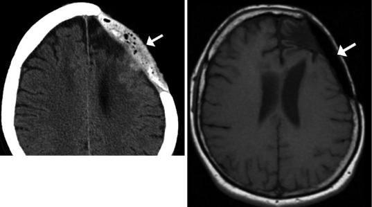
Intraoperatively fashioned acrylic cranioplasty is composed of methyl methacrylate resin that can be molded to a desired shape on the surgical field. The material tends to appear heterogeneous on CT and low signal on MRI (Fig. 4.21). The material often contains multiple foci of air due to the exothermic reaction that occurs when formed. The trapped bubbles should not be confused with infection. The methyl methacrylate at times can migrate prior to hardening, the appearance of which can potentially mimic hemorrhage on CT.
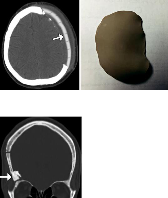
Preformed acrylic methyl methacrylate plates are specially molded to fit individual craniectomy defects using a computer-aided design system and 3D CT data. These flaps are usually secured to the adjacent calvarium using titanium plates and are thus continuous with the calvarium. On CT, preformed acrylic plates demonstrate homogeneous intermediate attenuation, around 100 HU (Fig. 4.22). Unlike the acrylic plates prepared intraoperatively, the preformed plates do not contain air bubbles. However, the preformed acrylic plates contain holes that are drilled to promote tissue ingrowth and leave a pathway to prevent accumulation of fluid in the epidural space.
Hydroxyapatite cement paste is sometimes used to close off small gaps in the calvarium. It can be molded to match the particular anatomy and can be applied in conjunction with other materials, such as titanium mesh. The cement
appears as homogeneously hyperattenuating on CT, similar in attenuation as natural bone (Fig. 4.23). On MRI, the hydroxyapatite appears as a signal void.
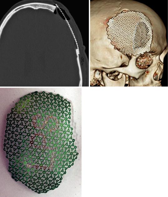
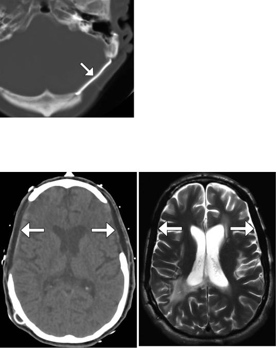
Titanium mesh is commonly used as a cranioplasty material. These plates generally produce good cosmetic results and minimal discomfort. Titanium produces minimal streak artifact on CT (Fig. 4.24). Solid titanium plates are now infrequently used but may be observed on follow-up imaging (Fig. 4.25).
Porous polyethylene implants are also suitable for covering cranial defects. This type of implant is also custom created for each patient using a computer-aided design system and 3D CT data. The material enables soft tissue and bone ingrowth and displays low attenuation on CT and low signal intensity on T2and T1-weighted MRI sequences (Fig. 4.26).
Synthetic bone grafts that are biocompatible have been developed for cranioplasty. For example, Bioplant HTR Synthetic Bone is a microporous composite of poly(methyl methacrylate) (PMMA), polyhydroxyethylmethacrylate (PHEMA), and calcium hydroxide. On CT, the HTR cranioplasty appears as heterogeneous with an overall attenuation that is greater than soft tissue but lower than bone (Fig. 4.27).
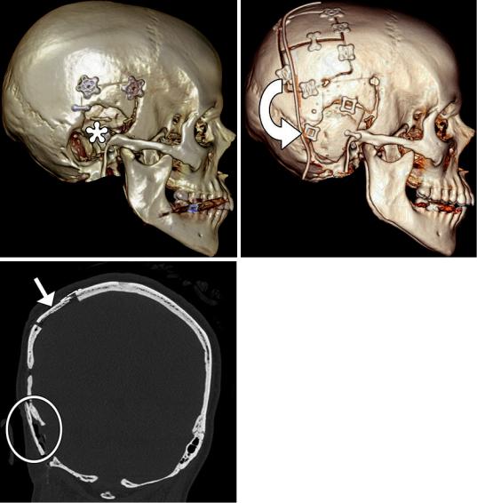
Autologous bone grafts can also be used for cranioplasty. These are often used in the form of split calvarial grafts in which the inner table is separated from the outer table in order to increase surface area for maximal coverage of a craniectomy defect (Fig. 4.28).
4 Imaging the Postoperative Scalp and Cranium |
133 |
|
|
a |
b |
Fig. 4.21 Intraoperatively fashioned acrylic cranio- |
nioplasty plate (arrow) has low signal on the correspond- |
plasty. Axial CT image (a) shows an acrylic cranioplasty |
ing T1-weighted MRI (b) |
flap containing low-attenuation bubbles (arrow). The cra- |
|
134 |
D.T. Ginat et al. |
|
|
a |
b |
Fig. 4.22 Preformed acrylic cranioplasty. Axial CT image (a) demonstrates a high-attenuation left frontal acrylic cranioplasty (arrow), conforming to the natural
Fig. 4.23 Hydroxyapatite cement. Coronal CT image shows the hyperattenuating material (arrow) filling a gap between the craniotomy flap and the adjacent skull
contours of the calvarium. The plate is traversed by numerous holes to allow tissue ingrowth. Photograph of customized acrylic cranioplasty flap without holes (b)
4 Imaging the Postoperative Scalp and Cranium |
135 |
|
|
a |
b |
c
Fig. 4.24 Titanium mesh cranioplasty. Axial (a) and 3D surface rendered (b) CT images show a titanium mesh that spans a left frontal craniectomy defect. Photograph (c) of a titanium mesh (Courtesy of Caroline Dufault, RN)
136 |
D.T. Ginat et al. |
|
|
Fig. 4.25 Titanium plate. Axial CT image shows the metal attenuation plate (arrow) that spans the left retrosigmoid craniectomy, which was performed in the 1980s
a |
b |
Fig. 4.26 Porex (porous polyethylene) cranioplasty. Axial CT image (a) shows bilateral low-attenuation implants (arrow). The cranioplasty material also displays low signal on T2-weighted (b) and T1-weighted (c) MR images

4 Imaging the Postoperative Scalp and Cranium |
137 |
|
|
c
Fig. 4.27 Synthetic (HTR) bone graft cranioplasty. Coronal CT image shows right hemicraniectomy with heterogeneously hyperattenuating cranioplasty material (arrow)
Fig.4.26 (continued)
138 |
D.T. Ginat et al. |
|
|
a |
b |
c
Fig. 4.28 Split-thickness bone graft cranioplasty. Initial 3D CT image (a) shows a right temporal skull defect (*). 3D CT image after cranioplasty (b) shows interval harvesting of bone from the right parietal calvarium and repositioning it into the temporal skull defect (curved
arrow). Corresponding coronal CT image (c) shows the split calvarium at the donor site (arrow) and the repositioned split calvarial graft in the right temporal region (encircled)