

76
.pdfStudy of forced vibrations transition processes . . . |
141 |
Substituting dz = −γdt, we get
dzdξ = η − Cγ1 (C0ξη + 12ξ2η + 12η3),
(27)
dηdz = −C2γ1 (3C0ξ2 + C0η2 + ξη2 + ξ3).
Integral curves in the plane ξ, η approach to the origin of coordinates, touching the straight line η = 0. Applying the substitution η = x1ξ, we have
dξ |
= x1ξ − |
C1C0 |
|
2 |
− |
C1 |
|
|
3 |
− |
C1 |
3 |
|
3 |
|
|
|
|
|||||||||
|
|
|
|
|
x1ξ |
|
|
|
|
x1 |
ξ |
|
|
|
x1 |
ξ |
|
|
|
|
|
||||||
dz |
γ |
|
|
2γ |
|
2γ |
|
|
|
|
(28) |
||||||||||||||||
dx1 |
|
3C1C0 |
|
|
|
|
C1 |
|
|
|
C1C0 |
|
|
|
|
C1 4 |
|
||||||||||
|
|
2 |
|
2 |
|
|
2 |
|
|
|
2 |
||||||||||||||||
|
= − |
|
|
ξ − x1 |
− |
|
ξ |
|
+ |
|
|
|
x1 |
ξ + |
|
x1 |
ξ |
|
|||||||||
dz |
2γ |
2γ |
|
|
2γ |
|
2γ |
|
|||||||||||||||||||
Now the integral curves in the plane ξx approach to the origin of coordinates, touching the straight line ξ = 0. Next, using the substitution ξ = x1y1, equation (28) is reduced to the form:
dz |
= |
|
2γ |
y12 + 2x1y1 + 4− 2γ x1y13 |
− |
2γ |
x12y12 − 2γ x13y13 |
− |
γ |
x15y13: |
||||||||
dy1 |
3C1C0 |
|
|
|
|
|
C1 |
|
3C1C0 |
|
C1 |
|
C1 |
|||||
|
|
|
|
|
|
|
|
|
|
|
|
|
|
|
|
|
|
(29) |
dz |
= − |
2γ |
|
x1y1 − x12 |
+ |
|
2γ 1−x12y12 + C0x13y1 + x16y122 |
|
|
|||||||||
|
|
|
|
|
||||||||||||||
dx1 |
|
|
3C1C0 |
|
|
C1 |
|
|
|
|
|
|
|
|
||||
|
|
|
|
|
|
|
|
|
|
|
|
|
|
|
|
|
|
|
Tangents to the integral curves at the coordinate origin on the plane x1, y1 are determined by the Theorem of Bendixson [4]
x1y1(x1 + |
C1C0 |
y1) = 0 |
(30) |
|
|||
|
γ |
|
|
However, in the equation tangents x1 = 0, y1 = 0 degenerate at the coordinate origin of the plane ξ, η, therefore, we consider only the integral curves, having at the coordinate origin
a tangent x1 + |
C1C0 |
y1 = 0. For this purpose, we apply the transformation |
||||||||||
|
|
|||||||||||
|
|
|
|
|
γ |
|
|
|
|
|||
|
|
|
|
|
|
|
|
|
x1 = (x2 − |
C1C0 |
)y1 |
|
|
|
|
|
|
|
|
|
|
γ |
|||
Then equation (29) takes the form |
|
|
||||||||||
|
|
|
− |
3C1C0 |
x2 + 3x22 + y12ϕ(x2, y2) |
|
|
|||||
|
dx2 |
= |
|
|
|
|
|
|||||
y1 |
|
γ |
|
(31) |
||||||||
|
|
C1C0 |
|
|
|
|||||||
|
dy2 |
2 |
|
|
|
|||||||
|
|
|
|
|
|
|
|
− 2x2 + y1 ψ(x2, y1) |
|
|
||
|
|
|
|
|
|
γ |
|
|
||||

142 Bissembayev K., Sultanova K.
where ϕ(x2, y1) and ψ(x2, y1) are polynomials relatively x2 and y1. Equation (31) can be presented as:
dx2 |
= −6x2 + B(x2, y1) |
(32) |
y1 dy1 |
where B(x2, y1) consists of the terms of higher degree relatively x2 and y1. Bendixson investigated the di erential equation of the form
x |
dy |
|
= ay + bx + B(x, y) |
(33) |
|
dx |
|||||
|
|
|
|||
and determined, that if a < 0, m – an odd number, then the origin of coordinates is a saddle point.
For equation (32) we have m = 1 (odd number) and a = −b < 0 so, the singular point (x2 = 0, y1 = 0) is a saddle; and the integral curves tend to it, having tangents x2 = 0, y1 = 0. Thus, as a result of all the transformations we have
ξ = x1y1 = (x2 − |
C1C0 |
2 |
2 |
|
C1C0 |
2 |
3 |
|
)y1 |
, η = x1ξ = x1y1 |
= ( |
|
) |
y1 |
|
γ |
γ |
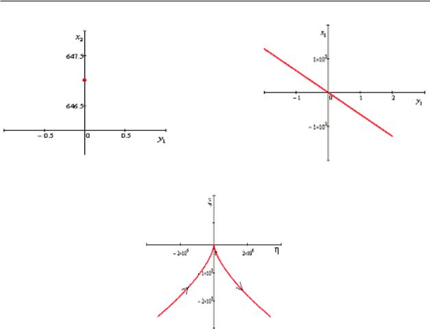
As it was mentioned previously, tangent y1 = 0 in the plane ξ, η reduces to the origin of coordinates; tangent x2 = 0 enters the curve
ξ = − |
C1C0 |
y12, η = ( |
C1C0 |
)2y13 |
(34) |
γ |
γ |
and we can assume, that it represents the integral curves in the neighborhood of the origin of the plane ξ, η.
Fig. 4 (in the corresponding coordinates) represents the tangent x2 = 0.
In conclusion we shall note, that this singular point is a saddle-node: as it can be seen from the equations (25), the representation point ξ(t), η(t) with increasing time is moving along the integral curve along the direction, indicated by arrows.
5 Conclusions
Peculiarities of integral curves of vibro-protective systems on rolling bearings in absence of rolling friction are investigated. Special points of integral curves ar defined and it is ascertained that special points are centre, saddle and centre. The special point D (in this case the
point of reference) is centre. Oscillation frequency (fig.8) changes depending on A and coin- n − 1
cides with frequency of external force frequency only in case, when A = (NnK1/p2 + 1)n − 2 . The special point B is regarded as sadle-knot.
Study of forced vibrations transition processes . . . |
143 |
a)
b)
c)
Figure 4: Integral curves in respective coordinates: a special point suits the point B in Fig. 2
References
[1]Zelenskiy G.A., Shevlyakov Yu.A. "Seysmoizolyatsiya zdaniy [Seismic isolation of buildings]" , M., Osnovaniya, fundamentyi i mehanika gruntov No 4 (1976): 19-21.
[2]Cherepinskiy Yu.D. "K seysmostoykosti zdaniy na kinematicheskih oporah [To earthquake resistance of buildings on kinematic supports]" , M., Osnovaniya, fundamentyi i mehanika gruntov No 3 (1973): 104-107.
[3]Polyakov S.V. "Sovremennoe sostoyanie i osnovnyie napravleniya v oblasti seysmostoykogo stroitelstva [Current state and main directions in the field of earthquake-resistant construction]" , Stroitelnaya mehanika i raschet sooruzheniy No 4 (1975): 8.
[4]Hayashi Т. "Nonlinear oscillations in physical systems" , M.: Mir (1968).
[5]Tondl А. "Nonlinear vibrations of mechanical systems" , M.: Mir (1973).
[6]Tondl А. "Autooscillations of mechanical systems" , M.: Mir (1979).
[7]Bissembayev K., Iskakov Zh. "Oscillations ofthe orthogonal mechanism with a non-ideal source of energy in the presence of a load on the operating link" , Mechanism and Machine Theory 92 (2015): 153-170.
[8]Jonuˇsas R., Juz˙enas E., Juz˙enas K., Meslinas N. "Modelling of rotor dynamics caused by ofdegradingbearings" , Mechanika Vol. 18(4) (2012): 438-441.

146 |
A.K. Tuleshov et al. |
1А.К. Тулешов, 2Б.М. Меркибаева, 3Б.А. Ахметова
1д.т.н., проф. Институт механики и машиноведения имени У.А. Джолдасбекова, г. Алматы, Казахстан, E-mail: aman_58@mail.ru
2PhD докторант, E-mail: bakhyta23@mail.ru
3PhD докторант, E-mail: balzhanibragimovna@mail.ru
2,3Казахский национальный университет им. аль-Фараби, г. Алматы, Казахстан
Кинематический анализ и синтез рычажного механизма штамповки кривошипного пресса
Расширение технических и технологических возможностей кузнечно-штамповочных машин и оборудования можно проводить за счет внедрения новых конструкций исполнительных механизмов с широкими функциональными возможностями. Такими возможностями обладает кривошипные рычажные механизмы пресса. В данной статье представлен кинематический анализ и синтез шестизвенного рычажного механизма штамповки кривошипного пресса с механизмом подачи поковки. Предлагается аналитический метод кинематического анализа механизма, который позволил реализовать программу численного расчета в интегрированной среде Maple. Разработаны методы кинематического синтеза шестизвенного механизма кривошипного пресса на основе среднеквадратического приближения, также синтеза четырехзвенного кривошипно-ползунного механизма подачи поковки. Определены все искомые постоянные геометрические параметры механизма штамповки, в результате механизм с высокой точностью реализовывает заданный закон движения рабочего ползуна. Сравнительный анализ проведен в среде ASIAN-2014.
Ключевые слова: кривошип, пресс, рычажный механизм, ползун, обработка материалов давлением.
1 Introduction
To increase the competitiveness of forging and stamping equipment, it is necessary to increase its operational characteristics (accuracy, durability, e ciency, high manufacturability) while reducing overall development and production costs [1, 2]. This encourages the transition to modern design methods based on mathematical modeling of ongoing processes throughout the technological cycle and rational use of modern CAD tools. Expanding the technical and technological capabilities of forging machines and equipment can be carried out by introducing new designs of actuators with wide functionality. These features are provided by the crank lever mechanisms of the press. The development begins with solving the problems of kinematic synthesis and analysis of mechanisms.
2 Literature review
The development of new machine mechanism designs, including crank presses [1], begins with solving problems of analysis and synthesis based on mathematical modeling. When implementing the technological process in crank presses, it is necessary to provide a specified cyclogram of the movement of the working slider: fast ascent, dwell, slow descent. Research on crank presses considers two ways to achieve this goal, the first is to synthesize a mechanism with a single degree of freedom [2, 3, 4, 5], where these properties are embedded in the properties of the kinematic chain, the second is the solution of this problem due to the additional freedom of the kinematic chain, which are called the hybrid press system [6].
M. Erkan Kyutyuk’s work [6] provides a review of the scientific literature on the analysis and synthesis of hybrid mechanisms of crank presses. In this paper, we consider a seven-way


148 |
A.K. Tuleshov et al. |
anism has the form [20].
Figure 1: Kinematic schemes of the stamping mechanism
I(1) IV (2, 3, 4, 5) II(6, 7) II(8, 9).
A special feature of the mechanism is that the modified contour BB C”C is a parallelogram and the ABB triangle is equilateral. This imposes certain conditions on the movement of individual joints: joint 2 makes a forward movement on the plane and joints 3 and 4 occupy the same angular positions.
The following symbols for the coordinates and dimensions of joints were introduced: r
– length of crank 1; a – height of ABB triangle; l – length of parallel connecting rods BC = B C ; ϕ – angular coordinate of crank 1; ψ – angular coordinate of two connecting rods 3 and 4; S – linear coordinate of slide 5; e – eccentricity of slide 5, i.e. the deviation of the trajectory of the center of gravity of the slider from Oy axis; b – distance between ball joint C and the center of the slide 5 along Ox axis; li,j – the length of the leash triangular joints, where i = 4.7 takes the number value of the joint j = 1, 2 – number of sides on a i triangle; li – the length of the i-joint; ϕi – angular coordinate of the i-joint; S9 – movement of slide 9 parallel to the axis O2x.
3.2 Kinematic analysis
The kinematics equations of the Stephenson mechanism I(1) IV (2, 3, 4, 5) in the crank press structure have the form [2]
r cos ϕ + l cos ψ = e
(1)
r sin ϕ − a + l sin ψ = −S

Kinematic analysis and synthesis of the lever mechanism . . . |
149 |
Solutions of equations (1) with respect to S = S(ϕ), ψ = ψ(ϕ) are obtained explicitly
|
S = a − r sin ϕ ± |
l2 − (e − r cos ϕ)2 |
(2) |
|||||||||||||
|
ψ = ± arccos l (e − r cos ϕ) |
|||||||||||||||
|
|
8 |
|
|
|
|
|
|
|
|
|
9 |
|
|||
|
|
1 |
|
|
|
|
|
|
|
|
|
|||||
|
The signs ± correspond to di erent assemblies of the mechanism. |
|||||||||||||||
|
The first and second derivative (analogs of speed and acceleration) are written as |
|||||||||||||||
|
ψ |
sin ψ = −rl sin ϕ |
|
|
|
|
|
|
(3) |
|||||||
|
S |
= −r cos ϕ − l cos ψ · ψ |
|
|
||||||||||||
|
ψ |
|
|
|
|
|
|
|
= −rl cos ϕ |
(4) |
||||||
|
sin ψ + cos ψ · ψ 2 |
|||||||||||||||
|
S |
= r sin ϕ + l sin ψ · ψ 2 − l cos ψ · ψ |
|
|||||||||||||
|
|
|
|
|
|
|
|
|
|
|||||||
|
Solutions of equations (3) and (4) with respect to the first and second derivative are |
|||||||||||||||
written as |
|
|
|
|
|
|
|
|
|
|
|
|
|
|
|
|
|
|
|
|
r sin(ϕ) |
|
|
||||||||||
1◦ |
Tψ(ϕ) = ψ = − |
|
|
|
|
|
, sin(ψ) = 0, ψ = 0, |
kπ, k = 1, 2, 3, . . . |
||||||||
l |
sin(ψ) |
|||||||||||||||
2◦ |
TS (ϕ) = S = −r cos ϕ − l · Tψ(ϕ) cos ψ, |
sin ψ = 0, ψ = 0, kπ, k = 1, 2, 3, . . . |
||||||||||||||
3◦ |
Tψ (ϕ) = ψ = −sin ψ ; l cos ϕ |
2− (Tψ)2 cos ψ<, |
||||||||||||||
|
|
1 |
|
|
r |
|
|
|||||||||
4◦ |
TS (ϕ) = S = r sin ϕ + l · (Tψ) |
sin ψ − l · Tψ cos ψ. |
||||||||||||||
(5)
In real crank presses, the eccentricity e = 0, the above formulas are slightly simplified and the algorithm for kinematic analysis of the mechanism is recorded
|
S = a − r sin ϕ ± |
l2 |
− r2 cos2 ϕ |
|
|
|
|
|
|
|
|
|
||||||||||||||||
1◦ |
|
|
|
|
|
; |
r |
|
|
< |
|
sin ϕ |
|
|
|
|
|
|
|
|
|
|
|
|||||
2◦ |
ψ = ± arccos |
l |
cos ϕ |
|
|
r2 cos2 |
ϕ |
|
|
|
|
|
|
|
|
|
||||||||||||
S = −r cos ϕ ± |
2 |
|
l2 |
|
|
|
|
|
|
|
|
|
|
|
||||||||||||||
|
|
|
|
|
|
|
|
|
|
|
r2 |
|
|
|
|
|
|
|
|
|
|
|
|
|
|
|
||
|
|
|
|
|
r sin ϕ |
|
|
|
− |
|
|
|
|
|
|
|
|
|
|
|
|
|
|
|||||
|
ψ = |
|
|
|
|
|
|
|
|
|
|
|
|
|
|
|
|
|
|
|
|
|
|
|
|
|
|
|
|
|
|
|
|
|
|
|
|
|
|
|
|
|
|
|
|
|
|
|
|
|
|
|
|
|
|
|
|
|
|
|
|
|
|
|
|
|
|
|
|
|
|
|
|
|
|
|
|
|
|
|
|
|
|
(6) |
||
|
|
|
|
|
|
|
2 |
|
|
|
|
|
|
|
|
|
|
|
|
|
|
|
|
|
|
|
||
|
|
|
|
|
|
|
|
|
|
|
|
|
|
|
|
|
|
|
|
|
|
|
|
|
|
|
|
|
|
|
|
|
l2 − r2 cos2 ϕ |
|
cos ϕ |
|
|
|
|
|
r2 sin2 ϕ cos ϕ |
|
|
||||||||||||||
|
S = r sin ϕ ± r |
|
|
|
|
|
|
|
|
− |
|
|
|
|
|
|||||||||||||
|
|
|
|
|
|
|
|
2(l2 |
− |
r2 cos2 ϕ)3/2 |
|
|||||||||||||||||
|
|
l2 |
− |
r2 cos2 ϕ |
|
|||||||||||||||||||||||
3◦ |
|
|
|
|
|
|
|
|
|
|
|
|
|
|
|
|
|
2 |
2 |
|
|
|
|
|
||||
|
|
|
|
|
|
|
|
|
cos ϕ |
|
|
|
|
|
r |
sin |
ϕ cos ϕ |
|
|
|
||||||||
|
|
|
|
|
|
|
|
|
|
|
|
|
|
|
|
|
|
|||||||||||
|
|
|
|
|
|
|
|
|
|
|
|
|
|
|
|
|
|
|
|
|
|
|
|
|
|
|
||
|
ψ = |
|
|
r |
|
|
|
|
|
|
|
|
|
|
|
|
|
|
|
|
|
|
|
|
|
|
|
|
|
|
|
|
|
|
|
|
|
|
|
|
|
|
|
|
|
|
|
|
|
|
|
|
|
||||
|
|
± |
|
l2 − r2 cos2 ϕ − 2(l2 − r2 cos2 ϕ)3/2 |
|
|
||||||||||||||||||||||
|
|
|
|
|
|
|
|
|
|
|
|
|
|
|
|
|
|
|
|
|
|
|
|
|
|
|
|
|
|
|
|
|
|
|
|
|
|
|
|
|
|
|
|
|
|
|
|
|
|
|
|
|
|
|
|
|
|
|
|
|
|
|
|
|
|
|
|
|
|
|
|
|
|
|
|
|
|
|
|
|
|
|
|
|
||
|
make the kinematics equations for the following mechanism structures II(6, 7) |
|
||||||||||||||||||||||||||
Next, we |
|
|
|
|
|
|
|
|
|
|
|
|
|
|
|
|
|
|
|
|
|
|
|
|
|
|
|
|
II(8, 9). To do this, write down the coordinates of the joints B and C : |
|
|||||||||||||||||||||||||||
xB = r cos ϕ + b, |
yB |
= r sin ϕ − a, |
xC = e + b, |
yC = S. |
|
(7) |
||||||||||||||||||||||

150 A.K. Tuleshov et al.
Let us write the equations of the geometric connection of a B DC triangle:
(xB − xD)2 + (yB − yD)2 = l412 , (xD − xC )2 + (yD − yC )2 = l422 ,
The solution of this system of equations with respect to two unknowns xD and yD can be
represented as [1] |
|
|
|
|
|
|
|
|
|
|
|||
|
|
= |
B ± √ |
|
|
|
|
|
|
|
|||
(xD)1,2 |
B2 − AC |
, |
(yD)1,2 = c(xD)1,2 + d, |
|
|
(8) |
|||||||
|
A |
|
|
||||||||||
|
|
|
|
|
|
|
|
|
|
|
|
||
where A = 1 + c2, B = c(yB − d), C = xB2 |
+ (yB − d)2 − l412 , |
|
|
||||||||||
c = |
xC |
− xB |
, d = |
l412 − l422 |
+ xC2 − xB2 + yC2 − yB2 |
, |
yC = yB . |
(9) |
|||||
|
|||||||||||||
|
yC |
− |
yB |
|
|
|
|
2(yC |
− |
yB ) |
|
|
|
|
|
|
|
|
|
|
|
|
|||||
Let us write similar geometric connection equations for the group II(6, 7)
(xD − xK )2 + (yD − yK )2 = l62, (xK − xO2 )2 + (yK − yO2 )2 = l712 ,
The xO2 , yO2 coordinates are calculated, then the solution of this system of equations
with respect to two unknowns xK and yK can be represented as |
|
|
|
|
|||||||||||||||
(xK )1,2 = |
B ± √ |
|
|
|
, (yK )1,2 = c(xK )1,2 + d, |
|
|
|
|
|
|
||||||||
B2 − AC |
|
|
|
|
|
(10) |
|||||||||||||
|
|
|
|
|
|
|
|
|
A |
|
|
|
|
|
|
||||
where A = 1 + c2, B = c(yD − d), C = xD2 + (yD − d)2 − l62, |
|
|
|
|
|
||||||||||||||
c = |
xO2 − xD |
, d = |
l62 − l712 + xO2 2 − xD2 + yO2 2 − yD2 |
, y |
|
= y |
|
. |
(11) |
||||||||||
yO2 − yD |
|
|
|
|
|
||||||||||||||
|
|
|
|
|
|
|
2(yO2 − yD) |
|
O2 |
|
D |
|
|||||||
Let us determine ϕ7 angle of the angular position of joint 7 (O2P ) using the formula |
|||||||||||||||||||
ϕ |
7 |
= 2π |
− |
β |
7 |
+ tan−1 |
yK − yO2 |
. |
|
|
|
|
|
(12) |
|||||
|
|
|
|
|
|
|
xK − xO2 |
|
|
|
|
|
|||||||
Now let us write the kinematics equations for the rocker-slider mechanism I(7) II(8, 9) in the following form
xN = xO2 + l7 cos ϕ7 + l8 cos ϕ8, yN = yO2 + l7 sin ϕ7 + l8 sin ϕ8.
Given that we have the kinematics equation xN |
− xO2 = S9 and yN − yO2 = h9 = const |
|||||||||||||||||
S9 = l7 cos ϕ7 + l8 cos ϕ8, l7 sin ϕ7 + l8 sin ϕ8 |
= h9. |
|
|
|
|
|
|
|
|
|
|
(13) |
||||||
Whence |
|
|
|
|
|
|
|
|
|
|
|
|
|
|
|
|
|
|
ϕ |
|
= |
± |
sin−1 |
h9 − l7 sin ϕ7 |
+ kπ, k = 0, 1, 2, 3, . . . , |
S |
|
= l |
|
cos ϕ |
|
+ l |
|
cos ϕ |
, |
(14) |
|
|
8 |
|
|
l7 |
|
|
9 |
|
7 |
|
7 |
|
8 |
8 |
|
|||