

Internet.Security
.pdf60 |
INTERNET SECURITY |
the 32-bit swap of the output of the 16th round encryption process. The output of the first round decryption is L15||R15 , which is the 32-bit swap of the input to the 16th round of encryption.
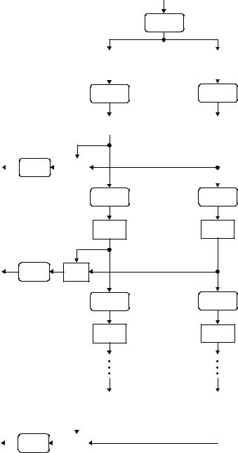
3.1.2Key Schedule
The 64-bit input key is initially reduced to a 56-bit key by ignoring every eighth bit. This is described in Table 3.1. These ignored 8 bits, k8, k16, k24, k32, k40, k48, k56, k64 are used as a parity check to ensure that each byte is of old parity and no errors have entered the key.
After the 56-bit key was extracted, they are divided into two 28-bit halves and loaded into
Y to the next iteration. These halves are concatenatedLin the ordered set and serve as input
two working registers. The halves in registers are shifted left either one or two positions, depending on the round. The number of bits shifted is given in Table 3.2.
After being shifted, the halves of 56 bits (Ci , Di ), 1 ≤ i ≤ 16, are used as the key input
to the Permuted Choice 2 (see Table 3.3), which produces a 48-biy key output. Thus, a different 48-bit key is generated for each round of DES. These 48-bit keys, K1, K2, . . . ,
K16 |
, are used for encryption at each round in the order from K1 through K16. The key |
|||||
|
|
F |
|
|||
schedule for DES is illustrated in Figure 3.3. |
|
|
|
|
||
|
|
56 |
× |
10 |
16 |
possible keys. Assuming that, on |
With a key length of 56 bits, these areM2 = 7.2 |
|
|||||
average, half the key space has to be searched, a single machine performing one DES |
||||||
|
A |
|
|
|
|
|
|
E |
|
|
|
|
|
|
T |
|
|
|
|
|
encryption per µs would take more than 1000 years to break the cipher. Therefore, a brute-force attack on DES appears to be impractical.
Table 3.1 |
Permuted choice 1 (PC-1) |
|
|
|
|
|
|
|
|
|
|
|
|||||
|
|
|
|
|
|
|
|
|
|
|
|
|
|
|
|
|
|
57 |
49 |
41 |
33 |
|
25 |
17 |
|
9 |
1 |
|
58 |
50 |
42 |
34 |
|
26 |
18 |
10 |
2 |
59 |
51 |
|
43 |
35 |
|
27 |
19 |
|
11 |
3 |
60 |
52 |
|
44 |
36 |
63 |
55 |
47 |
39 |
|
31 |
23 |
|
15 |
7 |
|
62 |
54 |
46 |
38 |
|
30 |
22 |
14 |
6 |
61 |
53 |
|
45 |
37 |
|
29 |
21 |
|
13 |
5 |
28 |
20 |
|
12 |
4 |
|
|
|
|
|
|
|
|
|
|
|
|
|
|
||||
Table 3.2 |
Schedule for key shifts |
|
|
|
|
|
|
|
|
|
|
|
|
||||
|
|
|
|
|
|
|
|
|
|
|
|
|
|
|
|
|
|
Round |
1 |
2 |
3 |
4 |
5 |
6 |
7 |
8 |
9 |
10 |
11 |
12 |
13 |
14 |
15 |
16 |
|
|
number |
|
|
|
|
|
|
|
|
|
|
|
|
|
|
|
|
Number of |
1 |
1 |
2 |
2 |
2 |
2 |
2 |
2 |
1 |
2 |
2 |
2 |
2 |
2 |
2 |
1 |
|
|
left shifts |
|
|
|
|
|
|
|
|
|
|
|
|
|
|
|
|
|
|
|
|
|
|
|
|
|
|
|
|
|
|
|
|
|
|
Table 3.3 Permuted choice 2 (PC-2)
14 |
17 |
11 |
24 |
1 |
5 |
3 |
28 |
15 |
6 |
21 |
10 |
23 |
19 |
12 |
4 |
26 |
8 |
16 |
7 |
27 |
20 |
13 |
2 |
41 |
52 |
31 |
37 |
47 |
55 |
30 |
40 |
51 |
45 |
33 |
48 |
44 |
49 |
39 |
56 |
34 |
53 |
46 |
42 |
50 |
36 |
29 |
32 |
|
|
|
|
|
|
|
|
|
|
|
|
Team-Fly®
SYMMETRIC BLOCK CIPHERS |
61 |
Key input (64 bits) |
|
PC-1 |
56 bits |
C0 |
28 bits |
|
|
|
|
|
|
|
LS (1)
C1 |
28 bits |
|
|
K1 |
|
PC-2 |
|
| | |
|
|
|||
|
|
|
|
|
48 bits
LS (1) |
|
C2 |
28 bits |
K2 |
PC-2 |
| | |
48 bits |
|
|
LS (2) |
|
C3 |
28 bits |
|
C16 |
28 bits |
|
|
|
|
|
|
|
|
|
K16 |
|
PC-2 |
|
| | |
|
|
48 bits
D0 |
28 bits |
|
|
|
|
|
|
|
LS (1)
D1 |
28 bits |
|
|
|
|
|
|
|
LS (1) |
|
D2 |
28 bits |
LS (2) |
|
D3 |
28 bits |
D16 |
28 bits |
|
|
|
|
Figure 3.3 Key schedule for DES.

62 |
INTERNET SECURITY |
Example 3.1 Assume that a 64-bit key input is K = 581fbc94d3a452ea, including 8 parity bits. Find the first three round keys only: K1, K2, and K3.
The register contents C0 (left) and D0 (right) are computed using Table 3.1:
C0 = bcd1a45
D0 = d22e87f
Using Table 3.2, the blocks C1 and D1 are obtained from the block C0 and D0 by shifting one bit to the left as follows:
C1 = 79a348b
D1 = a45d0ff
The 48-bit key K1 is derived using Table 3.3 (PC-2) by inputting the concatenated block (C1||D1) such that K1 = 27a169e58dda.
The concatenated block (C2||D2) is computed from (C1||D1) by shifting one bit to the left as shown below:
(C2||D2) = f346916 48ba1ff
Using Table 3.3 (PC-2), the 48-bit key K2 at round 2 is computed as K2 = da91ddd7b748. Similarly, (C3||D3) is generated from shifting (C2||D2) by two bits to the left as follows:
(C3||D3) = cd1a456 22e87fd
Using Table 3.3, we have
K3 = 1dc24bf89768
In a similar fashion, all the other 16-round keys can be computed and the set of entire DES keys is listed as follows:
K1 = 27a169e58dda |
K2 |
= da91ddd7b748 |
|||
K3 |
= 1dc24bf89768 |
K4 |
= 2359ae58fe2e |
||
K5 |
= b829c57c7cb8 |
K6 |
= 116e39a9787b |
||
K7 |
= c535b4a7fa32 |
K8 |
= d68ec5b50f76 |
||
K9 |
= e80d33d75314 |
K10 |
= e5aa2dd123ec |
||
K11 |
= 83b69cf0ba8d |
K12 |
= 7c1ef27236bf |
||
K13 |
= f6f0483f39ab |
K14 |
= 0ac756267973 |
||
K15 |
= 6c591f67a976 |
K16 |
= 4f57a0c6c35b |
||
3.1.3 DES Encryption
DES operates on a 64-bit block of plaintext. After initial permutation, the block is split into two blocks Li (left) and Ri (right), each 32 bits in length. This permuted plaintext

|
|
|
SYMMETRIC BLOCK CIPHERS |
|
|
63 |
|||
Table 3.4 Initial permutation (IP) |
|
|
|
|
|
||||
|
|
|
|
|
|
|
|
|
|
|
58 |
50 |
42 |
34 |
26 |
18 |
10 |
2 |
|
Li |
60 |
52 |
44 |
36 |
28 |
20 |
12 |
4 |
|
|
62 |
54 |
46 |
38 |
30 |
22 |
14 |
6 |
|
|
64 |
56 |
48 |
40 |
32 |
24 |
16 |
8 |
|
|
|
|
|
|
|
|
|
|
|
|
57 |
49 |
41 |
33 |
25 |
17 |
9 |
1 |
|
Ri |
59 |
51 |
43 |
35 |
27 |
19 |
11 |
3 |
|
|
61 |
53 |
45 |
37 |
29 |
21 |
13 |
5 |
|
|
63 |
55 |
47 |
39 |
31 |
23 |
15 |
7 |
|
|
|
|
|
|
|
|
|
|
|
Table 3.5 E bit-selection table
32 |
1 |
2 |
3 |
4 |
5 |
4 |
5 |
6 |
7 |
8 |
9 |
8 |
9 |
10 |
11 |
12 |
13 |
12 |
13 |
14 |
15 |
16 |
17 |
16 |
17 |
18 |
19 |
20 |
21 |
20 |
21 |
22 |
23 |
24 |
25 |
24 |
25 |
26 |
27 |
28 |
29 |
28 |
29 |
30 |
31 |
32 |
1 |
|
|
|
|
|
|
|
|
|
|
|
|
(see Table 3.4) has bit 58 of the input as its first bit, bit 50 as its second bit, and so on down to bit 7 as the last bit. The right half of the data, Ri , is expanded to 48 bits according to Table 3.5 of an expansion permutation.
The expansion symbol E of E(Ri ) denotes a function which takes the 32-bit Ri as input and produces the 48-bit E(Ri ) as output. The purpose of this operation is twofold – to make the output the same size as the key for the XOR operation, and to provide a longer result that is compressed during the S-box substitution operation.
After the compressed key Ki is XORed with the expanded block E(Ri−1) such that ) Ki for 1 ≤ i ≤ 15, this 48-bit i moves to substitution operations that are performed by eight Si -boxes. The 48-bit i is divided into eight 6-bit blocks. Each
6-bit block is operated on by a separate Si -box, as shown in Figure 3.2. Each Si -box is a table of 4 rows and 16 columns as shown in Table 3.6. This 48-bit input i to the S-boxes are passed through a nonlinear S-box transformation to produce the 32bit output.
If each Si denotes a matrix box defined in Table 3.6 and A denotes an input block of 6 bits, then Si (A) is defined as follows: the first and last bits of A represent the row number of the matrix Si , while the middle 4 bits of A represent a column number of Si in the range from 0 to 15.
For example, for the input (101110) to S5-box, denote as S105 (0111), the first and last bits combine to form 10, which corresponds to the row 2 (actually third row) of S5. The
64 |
|
|
|
|
|
|
|
INTERNET SECURITY |
|
|
|
|
|
|
|
|||
Table 3.6 |
S-boxes |
|
|
|
|
|
|
|
|
|
|
|
|
|
|
|||
|
|
|
0 |
1 |
2 |
3 |
4 |
5 |
6 |
7 |
8 |
9 |
10 |
11 |
12 |
13 |
14 |
15 |
|
|
|
|
|
|
|
|
|
|
|
|
|
|
|
|
|
|
|
|
0 |
|
14 |
4 |
13 |
1 |
2 |
15 |
11 |
8 |
3 |
10 |
6 |
12 |
5 |
9 |
0 |
7 |
S1 |
1 |
|
0 |
15 |
7 |
4 |
14 |
2 |
13 |
1 |
10 |
6 |
12 |
11 |
9 |
5 |
3 |
8 |
|
2 |
|
4 |
1 |
14 |
8 |
13 |
6 |
2 |
11 |
15 |
12 |
9 |
7 |
3 |
10 |
5 |
0 |
|
3 |
|
15 |
12 |
8 |
2 |
4 |
9 |
1 |
7 |
5 |
11 |
3 |
14 |
10 |
0 |
6 |
13 |
|
0 |
|
15 |
1 |
8 |
14 |
6 |
11 |
3 |
4 |
9 |
7 |
2 |
13 |
12 |
0 |
5 |
10 |
S2 |
1 |
|
3 |
13 |
4 |
7 |
15 |
2 |
8 |
14 |
12 |
0 |
1 |
10 |
6 |
9 |
11 |
5 |
|
2 |
|
0 |
14 |
7 |
11 |
10 |
4 |
13 |
1 |
5 |
8 |
12 |
6 |
9 |
3 |
2 |
15 |
|
3 |
|
13 |
8 |
10 |
1 |
3 |
15 |
4 |
2 |
11 |
6 |
7 |
12 |
0 |
5 |
14 |
9 |
|
0 |
|
10 |
0 |
9 |
14 |
6 |
3 |
15 |
5 |
1 |
13 |
12 |
7 |
11 |
4 |
2 |
8 |
S3 |
1 |
|
13 |
7 |
0 |
9 |
3 |
4 |
6 |
10 |
2 |
8 |
5 |
14 |
12 |
11 |
15 |
1 |
|
2 |
|
13 |
6 |
4 |
9 |
8 |
15 |
3 |
0 |
11 |
1 |
2 |
12 |
5 |
10 |
14 |
7 |
|
3 |
|
1 |
10 |
13 |
0 |
6 |
9 |
8 |
7 |
4 |
15 |
14 |
3 |
11 |
5 |
2 |
12 |
|
0 |
|
7 |
13 |
14 |
3 |
0 |
6 |
9 |
10 |
1 |
2 |
8 |
5 |
11 |
12 |
4 |
15 |
S4 |
1 |
|
13 |
8 |
11 |
5 |
6 |
15 |
0 |
3 |
4 |
7 |
2 |
12 |
1 |
10 |
14 |
9 |
|
2 |
|
10 |
6 |
9 |
0 |
12 |
11 |
7 |
13 |
15 |
1 |
3 |
14 |
5 |
2 |
8 |
4 |
|
3 |
|
3 |
15 |
0 |
6 |
10 |
1 |
13 |
8 |
9 |
4 |
5 |
11 |
12 |
7 |
2 |
14 |
|
0 |
|
2 |
12 |
4 |
1 |
7 |
10 |
11 |
6 |
8 |
5 |
3 |
15 |
13 |
0 |
14 |
9 |
S5 |
1 |
|
14 |
11 |
2 |
12 |
4 |
7 |
13 |
1 |
5 |
0 |
15 |
10 |
3 |
9 |
8 |
6 |
|
2 |
|
4 |
2 |
1 |
11 |
10 |
13 |
7 |
8 |
15 |
9 |
12 |
5 |
6 |
3 |
0 |
14 |
|
3 |
|
11 |
8 |
12 |
7 |
1 |
14 |
2 |
13 |
6 |
15 |
0 |
9 |
10 |
4 |
5 |
3 |
|
0 |
|
12 |
1 |
10 |
15 |
9 |
2 |
6 |
8 |
0 |
13 |
3 |
4 |
14 |
7 |
5 |
11 |
S6 |
1 |
|
10 |
15 |
4 |
2 |
7 |
12 |
9 |
5 |
6 |
1 |
13 |
14 |
0 |
11 |
3 |
8 |
|
2 |
|
9 |
14 |
15 |
5 |
2 |
8 |
12 |
3 |
7 |
0 |
4 |
10 |
1 |
13 |
11 |
6 |
|
3 |
|
4 |
3 |
2 |
12 |
9 |
5 |
15 |
10 |
11 |
14 |
1 |
7 |
6 |
0 |
8 |
13 |
|
0 |
|
4 |
11 |
2 |
14 |
15 |
0 |
8 |
13 |
3 |
12 |
9 |
7 |
5 |
10 |
6 |
1 |
S7 |
1 |
|
13 |
0 |
11 |
7 |
4 |
9 |
1 |
10 |
14 |
3 |
5 |
12 |
2 |
15 |
8 |
6 |
|
2 |
|
1 |
4 |
11 |
13 |
12 |
3 |
7 |
14 |
10 |
15 |
6 |
8 |
0 |
5 |
9 |
2 |
|
3 |
|
6 |
11 |
13 |
8 |
1 |
4 |
10 |
7 |
9 |
5 |
0 |
15 |
14 |
2 |
3 |
12 |
|
0 |
|
13 |
2 |
8 |
4 |
6 |
15 |
11 |
1 |
10 |
9 |
3 |
14 |
5 |
0 |
12 |
7 |
S8 |
1 |
|
1 |
15 |
13 |
8 |
10 |
3 |
7 |
4 |
12 |
5 |
6 |
11 |
0 |
14 |
9 |
2 |
|
2 |
|
7 |
11 |
4 |
1 |
9 |
12 |
14 |
2 |
0 |
6 |
10 |
13 |
15 |
3 |
5 |
8 |
|
3 |
|
2 |
1 |
14 |
7 |
4 |
10 |
8 |
13 |
15 |
12 |
9 |
0 |
3 |
5 |
6 |
11 |
middle 4 bits combine to form 0111, which corresponds to the column 7 (actually the eighth column) of the same S5-box. Thus, the entry under row 2, column 7 of S5-box is computed as:
S105 (0111) = S25(7) = 8 (hexadecimal) = 1000 (binary)
Thus, the value of 1000 is substituted for 101110. That is, the four-bit output 1000 from S5 is substituted for the six-bit input 101110 to S5. Eight four-bit blocks are the S-box output resulting from the substitution phase, which recombine into a single 32-bit block i by concatenation. This 32-bit output i of the S-box substitution are permuted according to Table 3.7. This permutation maps each input bit of i to an output position of P( i ).

|
SYMMETRIC BLOCK CIPHERS |
65 |
||
Table 3.7 Permutation function P |
|
|
||
|
|
|
|
|
16 |
7 |
20 |
21 |
|
29 |
12 |
28 |
17 |
|
1 |
15 |
23 |
26 |
|
5 |
18 |
31 |
10 |
|
2 |
8 |
24 |
14 |
|
32 |
27 |
3 |
9 |
|
19 |
13 |
30 |
6 |
|
22 |
11 |
4 |
25 |
|
|
|
|
|
|
Table 3.8 Inverse of initial permutation, IP−1
40 |
8 |
48 |
16 |
56 |
24 |
64 |
32 |
39 |
7 |
47 |
15 |
55 |
23 |
63 |
31 |
38 |
6 |
46 |
14 |
54 |
22 |
62 |
30 |
37 |
5 |
45 |
13 |
53 |
21 |
61 |
29 |
36 |
4 |
44 |
12 |
52 |
20 |
60 |
28 |
35 |
3 |
43 |
11 |
51 |
19 |
59 |
27 |
34 |
2 |
42 |
10 |
50 |
18 |
58 |
26 |
33 |
1 |
41 |
9 |
49 |
17 |
57 |
25 |
|
|
|
|
|
|
|
|
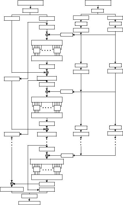
The output P( i ) are obtained from the input i by taking the 16th bit of i as the first bit of P( i ), the seventh bit as the second bit of P( i ), and so on until the 25th bit of i is taken as the 32nd bit of P( i ). Finally, the permuted result is XORed with the left half Li of the initial permuted 64-bit block. Then the left and right halves are swapped and another round begins. The final permutation is the inverse of the initial permutation, and is described in Table 3.8 IP−1. Note here that the left and right halves are not swapped after the last round of DES. Instead, the concatenated block R16||L16 is used as the input to the final permutation of Table 3.8 (IP−1). Thus, the overall structure for DES algorithm is shown in Figure 3.4.
Example 3.2 Suppose the 64-bit plaintext is X = 3570e2f1ba4682c7, and the same key as used in Example 3.1, K = 581fbc94d3a452ea is assumed again. The first two-round keys are, respectively, K1 = 27a169e58dda and K2 = da91ddd76748.
For the purpose of demonstration, the DES encryption aims to limit the first two rounds only. The plaintext X splits into two blocks (L0, R0) using Table 3.4 IP such that L0 = ae1ba189 and R0 = dc1f10f4.
The 32-bit R0 is expanded to the 48-biy E(R0) such that E(R0) = 6f80fe8a17a9.
The key-dependent function i is computed by XORing E(R0) with the first round key K1, such that
1 = E(R0) K1
= 4821976f9a73
66 |
INTERNET SECURITY |
|
|
X |
|
Plaintext input |
64 bits |
|
|
|
|
|
IP |
|
|
|
L0 |
|
32 bits |
R0 |
32 bits |
|
|
|
|
|
|
E(R0) |
|
|
|
|
|
|
48 bits |
|
|
|
|
|
|
K1 |
PC-2 |
|
|
|
|
|
|
|
|
|
|
|
Γ1 = E(R0) K1 (48 bits) |
||
|
|
|
|
S1 |
|
S8 |
|
|
|
|
|
Ω1 (32 bits) |
|
|
|
|
|
|
P(Ω1) |
|
|
|
|
|
|
32 bits |
|
L |
1 |
= R |
0 |
R1 = P(Ω1) L0 32 bits |
||
|
|
|
|
|
||
|
|
32 bits |
E(R1) |
48 bits |
||
|
|
|
|
|
K2 |
PC-2 |
|
|
|
|
48 bits |
||
|
|
|
|
|
||
|
|
|
|
Γ2 = E(R1) K2 (48 bits) |
||
|
|
|
|
S1 |
|
S8 |
|
|
|
|
|
Ω2 (32 bits) |
|
|
|
|
|
|
P(Ω2) |
|
L2 = R1 |
R2 = P(Ω2) L1 |
|||||
|
|
32 bits |
32 bits |
|||
|
|
|
|
|||
|
|
E(R15) |
|
|
R15 |
K16 |
PC-2 |
|
|
||
L15 |
Γ16 = E(R15) K16 (48 bits) |
|
|
|
S1 |
S8 |
|
|
|
Ω16 (32 bits) |
|
|
|
P(Ω16) |
|
R16 = P(Ω16) L15 |
L16 = R15 |
|
|
|
IP−1 |
|
|
Y |
Ciphertext output |
64 bits |
|
K |
Key input |
64 bits |
|
|
|
|
PC-1 |
56 bits |
|
C0 |
28 bits |
D0 |
28 bits |
|
LS |
|
LS |
|
|
C |
1 |
|
D1 |
|
|
|
|
|
|
LS |
LS |
|
C |
2 |
D2 |
|
|
|
LS |
LS |
|
C |
3 |
D3 |
|
|
|
Figure 3.4 Block cipher design of DES.
SYMMETRIC BLOCK CIPHERS |
67 |
This 48-bit 1 is first divided into eight six-bit blocks, and then fed into eight Si -boxes. The output 1 resulting from the S-box substitution phase is computed as 1 = a1ec961c.
Using Table 3.7, the permuted values of 1 are P( 1) = 2ba1536c. Modulo-2 addition of P( 1) with L0 becomes
R1 = P( 1) L0
= 85baf2e5
Since L1 = R0, this gives L1 = dc1f10f4.
Consider next the second-round encryption. Expanding R1 with the aid of Table 3.5 yields E(R1) = c0bdf57a570b. XORing E(R1) with K2 produces
2 = E(R1) K2
= 1a2c28ade043
The substitution operations with S-boxes yields the 32-bit output 2 such that 2 = 1ebcebdf. Using Table 3.7, the permutation P( 2) becomes P ( 2) = 5f3e39f7. Thus, the right-half output R2 after round two is computed as
R2 = P( 2) L1
= 83212903
The left-half output L2 after round two is immediately obtained as
L2 = R1 = 85baf2e5
Concatenation of R2 with L2 is called the preoutput block in our two-round cipher system. The preoutput is then subjected to the inverse permutation of Table 3.8. Thus, the output of the DES algorithm at the end of the second round becomes the ciphertext Y:
Y= IP−1(R2||L2)
= d7698224283e0aea
3.1.4DES Decryption
The decryption algorithm is exactly identical to the encryption algorithm except that the round keys are used in the reverse order. Since the encryption keys for each round are K1, K2, . . . , K16, the decryption keys for each round are K16, K15, . . . , K1. Therefore, the same algorithm works for both encryption and decryption. The DES decryption process will be explained in the following example.
Example 3.3 Recover the plaintext X from the ciphertext Y = d7698224283e0aea (computed in Example 3.2). Using Table 3.4 in the first place, divide the ciphertext Y into the two blocks:
68 INTERNET SECURITY
R2 = 83212903
L2 = 85baf2e5
Applying Table 3.5 to L2 yields E(L2) = c0bdf57a570b.
E(L2) is XORed with K2 such that
2 = E(L2) K2
= 1a2c28ade043
This is the 48-bit input to the S-boxes.
After the substitution phase of S-boxes, the 32-bit output 2 from the S-boxes is computed as 2 = 1ebcebdf. From Table 3.7, the permuted values of 2 are P( 2) =
5f3e39f7.
Moving up to the first round, we have L1 = P( 2) R2 = dc1f10f4. Applying Table 3.5 for L1 yields E(L1) = 6f80fe8a17a9.
XORing E(L1) with K1, we obtain the 48-bit input to the S-boxes.
1 = E(L1) K1
= 4821976f9a73
The 32-bit output from the S-boxes is computed as:
1 = a1ec961c
Using Table 3.7 for permutation, we have
P( 1) = 2ba1536c
The preoutput block can be computed as follows:
L0 = P( 1) R1 = ae1ba189
R0 = L1 = dc1f10f4
L0||R0 = ae1ba189dc1f10f4 (preoutput block)
Applying Table 3.8 (IP−1) to the preoutput block, the plaintext X is restored as follows:
X= IP−1(L0||R0 )
= 3570e2f1ba4682c7
Example 3.4 Consider the encryption problem of plaintext
X = 785ac3a4bd0fe12d with the original input key
K = 38a84ff898b90b8f.

SYMMETRIC BLOCK CIPHERS |
69 |
The 48-bit round keys from K1 through K16 are computed from the 56-bit key blocks through a series of permutations and left shifts, as shown below:
Compressed round keys
K1 = 034b8fccfd2e |
K2 |
= 6e26890ddd29 |
|||
K3 |
= 5b9c0cca7c70 |
K4 |
= 48a8dae9cb3c |
||
K5 |
= 34ec2e915e9a |
K6 |
= e22d02dd1235 |
||
K7 |
= 68ae35936aec |
K8 |
= c5b41a30bb95 |
||
K9 |
= c043eebe209d |
K10 |
= b0d331a373c7 |
||
K11 |
= 851b6336a3a3 |
K12 |
= a372d5f60d47 |
||
K13 |
= 1d57c04ea3da |
K14 |
= 5251f975f549 |
||
K15 |
= 9dc1456a946a |
K16 |
= 9f2d1a5ad5fa |
||
The 64-bit plaintext X splits into two blocks (L0, R0), according to Table 3.4 (IP), such that
L0 = 4713b8f4
R0 = 5cd9b326
The 32-bit R0 is spread out and scrambled in 48 bits, using Table 3.5, such that E(R0) =
2f96f3da690c.
The 48-bit input to the S-box, 1, is computed as:
1 = E(R0) K1
= 2cdd7c169422
The 32-bit output from the S-box is 1 = 28e8293b.
Using Table 3.7, P( 1) becomes
P( 1) = 1a0b2fc4
XORing P( 1) with L0 yields
R1 = P( 1) L0
= 5d189730
which is the right-half output after round one.
Since L1 = R0, the left-half output L1 after round one is L1 = 5cd9b326. The first round of encryption has been completed.
In similar fashion, the 16-round output block (Li , Ri ), 2 ≤ i ≤ 16, can be computed as follows: