

Internet.Security
.pdf30 |
INTERNET SECURITY |
|
|
IP layer |
|
|
|
IP packet |
|
ARP |
|
Output module |
|
|
|
|
|
Cache |
|
|
Queues |
table |
|
|
|
|
|
Y |
|
Check entry |
|
||
by entry |
|
|
|
|
|
|
|
Cache-control |
|
L |
|
|
Input module |
||
module |
|
||
|
F |
||
|
|
Request |
Reply |
|
|
M |
|
Request |
A |
Request |
|
|
|
||
EARP packet |
|
||
T |
|
|
|
|
|
Physical access layer |
|
|
|
Transmission |
|
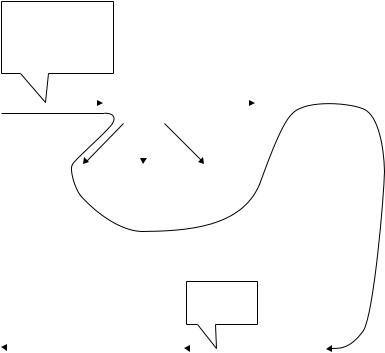
Figure 2.5 Simplified ARP package.
•The cache table has an array of entries used and updated by ARP messages. It is inefficient to use the ARP protocol for each datagram destined for the same host or router. The solution is to use the cache table. The cache table is implemented as an array of entries. When a host or router receives the corresponding physical address for an IP datagram, the address can be saved in the cache table within the next few minutes. However, mapping in the cache should not be retained for an unlimited time, due to the limited cache space.
•A queue contains packets going to the same destination. The ARP package maintains a set of queues to hold the IP packets, while ARP tries to resolve the physical address. The output module sends unresolved packets to the corresponding queue. The input
Team-Fly®
TCP/IP SUITE AND INTERNET STACK PROTOCOLS |
31 |
module removes a packet from a queue and sends it to the physical access layer for transmission.
•The output module takes an IP packet from the IP layer and sends it to a queue as well as the physical access layer. The output module checks the cache table to find an entry corresponding to the destination IP address of this packet. If the entry is found and the state of the entry is resolved, the packet, along with the destination physical address, is passed to the physical access layer (or data link layer) for transmission. If the entry is found and the state of the entry is pending, the packet should wait until the destination physical address is found. If no entry is found, the module creates a queue and enqueues the packet. A new cache entry (‘pending’) is created for the destination and the attempt field is set to 1. An ARP request is then broadcast.
•The input module waits until an ARP request or reply arrives. The input module checks the cache table to find an entry corresponding to this packet (request or reply).
If the entry is found and the state of the entry is ‘pending’, the module updates the entry by copying the target physical address in the packet to the physical address field of the entry and changing the state to ‘resolved’. The module also sets the value of the time-out for the entry and then dequeues the packets from the corresponding queue, one by one, and delivers them along with the physical address to the physical access layer for transmission.
If the entry is found and the state is ‘resolved’, the module still updates the entry. This is because the target physical address could have been changed. The value of the time-out field is also reset. If the entry is not found, the module creates a new entry and adds it to the cache table.
Now the module checks to see if the arrived ARP packet is a request. If it is, the input module immediately creates an ARP reply message and sends it to the sender. The ARP reply packet is created by changing the value of the operation field from request to reply and filling in the target physical address.
•The cache-control module is responsible for maintaining the cache table. It checks the cache table periodically, entry by entry. If the entry is free, it continues to the next entry. If the state is ‘pending’, the module increments the value of the attempts field by 1. It then checks the value of the attempts field. If this value is greater than the maximum number of attempts allowed, the state is changed to ‘free’ and the corresponding queue is destroyed. However, if the number of attempts is less than the maximum, the input module creates and sends another ARP request. If the state of the entry is ‘resolved’, the module decrements the value of the ‘time-out’ field by the amount of the time elapsed since the last check. If this value is less than or equal to zero, the state is changed to free and the queue is destroyed.
2.1.3 Reverse Address Resolution Protocol (RARP)
To create an IP datagram, a host or a router needs to know its own IP address, which is independent of the physical address. The RARP is designed to resolve the address mapping of a machine in which its physical address is known, but its logical (IP) address is unknown. The machine can get its physical address, which is unique locally. It can then use the physical address to get the logical IP address using the RARP protocol. In
32 INTERNET SECURITY
Physical address is given. Request IP address
H |
|
|
|
|
|
|
RARP |
|
|
|
|
|
S |
|||
|
|
|
|
|
|
request |
|
|
|
|
|
|||||
|
|
|
|
|
|
|
|
|
|
|
|
|
||||
|
|
|
|
|
|
|
|
|
|
|
|
|
|
|
|
|
Host |
|
|
|
|
|
|
|
|
|
Server |
||||||
|
|
|
|
|
|
|
|
|
|
|
|
|
|
|
|
|
|
|
|
|
|
|
|
|
|
|
|
|
|
|
|
|
|
|
|
|
M1 |
|
|
M2 |
|
|
|
|
M3 |
|
|
|
||
|
|
|
|
|
|
|
|
|
|
|
|
|
|
|
||
|
|
(a) Request for the physical address by broadcast |
||||||||||||||
|
|
|
|
|
|
|
|
|
|
|
|
|
Reply IP |
|||
|
|
|
|
|
|
|
|
|
|
|
|
|
Address |
|||
|
|
IP address |
|
|
|
|
|
|
|
|
|
|
|
|
||
H |
|
|
|
RARP |
|
|
|
|
|
S |
||||||
|
|
|
|
|
|
|
|
|
|
|
||||||
|
|
|
|
|
|
reply |
|
|
|
|
|
|||||
|
|
|
|
|
|
|
|
|
|
|
|
|
||||
|
|
|
|
|
|
|
|
|
|
|
|
|
|
|
|
|
Host |
|
|
|
|
|
|
|
|
|
|
|
Server |
||||
|
|
|
|
|
|
|
|
|
|
|
|
|||||
|
|
(b) Reply IP address by unicast |
|
|
|
|
||||||||||
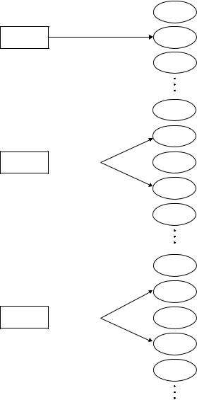
Figure 2.6 RARP dynamic mapping.
reality, RARP is a protocol of dynamic mapping in which a given physical address is associated with a logical IP address, as shown in Figure 2.6.
To get the IP address, a RARP request is broadcast to all systems on the network. Every host or router on the physical network will receive the RARP request packet, but the RARP server will only answer it as shown in Figure 2.6(b). The server sends a RARP reply packet including the IP address of the requestor.
2.1.4Classless Interdomain Routing (CIDR)
CIDR is the standard that specifies the details of both classless addressing and an associated routing scheme. Accordingly, the name is slightly inaccurate designation because CIDR specifies addressing as well as routing.
The original IPv4 model built on network classes was a useful mechanism for allocating identifiers (netid and hostid) when the primary users of the Internet were academic and research organisations. But, this mode proved insufficiently flexible and inefficient as the Internet grew rapidly to include gateways into corporate enterprises with complex
TCP/IP SUITE AND INTERNET STACK PROTOCOLS |
33 |
networks. By September 1993, it was clear that the growth in Internet users would require an interim solution while the details of IPv6 were being finalised. The resulting proposal was submitted as RFC 1519 titled ‘Classless Inter-Domain Routing (CIDR): an Address Assignment and Aggregation Strategy.’ CIDR is classless, representing a move away from the original IPv4 network class model. CIDR is concerned with interdomain routing rather than host identification. CIDR has a strategy for the allocation and use of IPv4 addresses, rather than a new proposal.
2.1.5 IP Version 6 (IPv6, or IPng)
The evolution of TCP/IP technology has led on to attempts to solve problems that improve service and extend functionalities. Most researchers seek new ways to develop and extend the improved technology, and millions of users want to solve new networking problems and improve the underlying mechanisms. The motivation behind revising the protocols arises from changes in underlying technology: first, computer and network hardware continues to evolve; second, as programmers invent new ways to use TCP/IP, additional protocol support is needed; third, the global Internet has experienced huge growth in size and use. This section examines a proposed revision of the Internet protocol which is one of the most significant engineering efforts so far.
The network layer protocol is currently IPv4. IPv4 provides the basic communication mechanism of the TCP/IP suite. Although IPv4 is well designed, data communication has evolved since the inception of IPv4 in the 1970s. Despite its sound design, IPv4 has some deficiencies that make it unsuitable for the fast-growing Internet. The IETF decided to assign the new version of IP and to name it IPv6 to distinguish it from the current IPv4. The proposed IPv6 protocol retains many of the features that contributed to the success of IPv4. In fact, the designers have characterised IPv6 as being basically the same as IPv4 with a few modifications: IPv6 still supports connectionless delivery, allows the sender to choose the size of a datagram, and requires the sender to specify the maximum number of hops a datagram can make before being terminated. In addition, IPv6 also retains most of IPv4’s options, including facilities for fragmentation and source routing.
IP version 6 (IPv6), also known as the Internet Protocol next generation (IPng), is the new version of the Internet Protocol, designed to be a full replacement for IPv4. IPv6 has an 128-bit address space, a revised header format, new options, an allowance for extension, support for resource allocation and increased security measures. However, due to the huge number of systems on the Internet, the transition from IPv4 to IPv6 cannot occur at once. It will take a considerable amount of time before every system in the Internet can move from IPv4 to IPv6. RFC 2460 defines the new IPv6 protocol. IPv6 differs from IPv4 in a number of significant ways:
•The IP address length in IPv6 is increased from 32 to 128 bits.
•IPv6 can automatically configure local addresses and locate IP routers to reduce configuration and setup problems.
•The IPv6 header format is simplified and some header fields dropped. This new header format improves router performance and make it easier to add new header types.
•Support for authentication, data integrity and data confidentiality are part of the IPv6 architecture.
34 |
INTERNET SECURITY |
•A new concept of flows has been added to IPv6 to enable the sender to request special handling of datagrams.
IPv4 has a two-level address structure (netid and hostid) categorised into five classes (A, B, C, D and E). The use of address space is inefficient. For instant, when an organisation is granted a class A address, 16 million addresses from the address space are assigned for the organisation’s exclusive use. On the other hand, if an organisation is granted a class C address, only 256 addresses are assigned to this organisation, which may not be enough. Soon there will be no addresses left to assign to any new system that wants to be connected to the Internet.
Although the subnetting and supernetting strategies have alleviated some addressing problems, subnetting and supernetting make routing more complicated. The encryption and authentication options in IPv6 provide confidentiality and integrity of the packet. However, no encryption or authentication is provided by IPv4.
2.1.5.1IPv6 Addressing
In December 1995, the network working group of IETF proposed a longer-term solution for specifying and allocating IP addresses. RFC 2373 describes the address space associated with the IPv6. The biggest concern with Internet developers will be the migration process from IPv4 to IPv6.
IPv4 addressing has the following shortcoming: IPv4 was defined when the Internet was small and consisted of networks of limited size and complexity. It offered two layers of address hierarchy (netid and hostid) with three address formats (class A, B and C) to accommodate varying network sizes. Both the limited address space and the 32-bit address size in IPv4 proved to be inadequate for handling the increase in the size of the routing table caused by the immense numbers of active hosts and servers. IPv6 is designed to improve upon IPv4 in each of these areas. IPv6 allocates 128 bits for addresses. Analysis shows that this address space will suffice to incorporate flexible hierarchies and to distribute the responsibility for allocation and management of the IP address space.
Like IPv4, IPv6 addresses are represented as string of digits (128 bits or 32 hex digits) which are further broken down into eight 16-bit integers separated by colons (:). The basic representation takes the form of eight sections, each two bytes in length.
xx:xx:xx:xx:xx:xx:xx:xx
where each xx represents the hexadecimal form of 16 bits of address. IPv6 uses hexadecimal colon notation with abbreviation methods.
Example 2.4 An IPv6 address consists of 16 bytes (octets) which is 128 bits long. The IPv6 address consists of 32 hexadecimal digits, with every four digits separated by a colon.

|
TCP/IP SUITE AND INTERNET STACK PROTOCOLS |
35 |
|
IPv6 address: |
flea:1075:fffb:110e:0000:0000:7c2d:a65f |
|
|
|
|
|
|
|
|
|
|
Abbreviated address: |
f1ea:1075:fffb:110e::7c2d:a65f |
|
|
|
|
|
|
|
|
|
|
Binary address: |
1111000111101010 . . . 1010011001011111 |
|
|
Many of the digits in IPv6 addresses are zeros. In this case, the abbreviated address can be obtained by omitting the leading zeros of a section (four hex digits between two colons), but not the trailing zeros.
Example 2.5 Assume that the IPv6 address is given as
fedc:ab98:0052:4310:000f:bccf:0000:ff1f (unabbreviated)
Using the abbreviated form, 0052 can be written as 52, 000f as f, and 0000 as 0. But the trailing zeros cannot be dropped, so that 4310 would not be abbreviated. Thus, the given IP address becomes fedc:ab98:52:4310:f:bccf:0:ff1f (abbreviated).
Example 2.6 Consider an abbreviated address with consecutive zeros. When consecutive sections are composed of zeros, further abbreviations are possible. We can remove the zeros altogether and replace them with a double semicolon.
fedc:0:0:0:0:abf8:0:f75f (abbreviated)
fedc::abf8:0:f75f (more abbreviated)
IPv6 Address Types
IPv6 has identified three types of addresses:
•Unicast : To associate with a specific physical interface to a network. Packets sent to a unicast address are delivered to the interface uniquely specified by the address.
•Anycast : To associate with a set of physical interfaces, generally on different modes. Packets sent to an anycast address will be delivered to at least one interface specified by the address.
•Multicast : To associate with a set of physical interfaces, generally on multiple hosts (nodes). Packets sent to a multicast address will be delivered to all the interfaces to which the address refers.
Figure 2.7 illustrates three address types.
IPv6 addresses divide the address space into two parts with the type prefix for each type of address, rest of address, and the fraction of each type of address relative to the whole address space. Table 2.5 illustrates the address space assignment for type prefixes.
36 |
INTERNET SECURITY |
|
Host 1 |
Unicast |
IP packet |
Host 2 |
|
|
Host 3 |
Host 1
Host 2
or
Anycast  Host 3 or
Host 4
Host 5
Host 1
Host 2
and
Multicast  Host 3 and
Host 4
Host 5
Figure 2.7 IPv6 address types.
2.1.5.2IPv6 Packet Format
The IPv6 protocol consists of two parts: the basic elements of the IPv6 header and IPv6 extension headers. The IPv6 datagram is composed of a base header (40 bytes) followed by the payload. The payload consists of two parts: optional extension headers and data from the upper layer. The extension headers and data packet from the upper layer usually

|
|
TCP/IP SUITE AND INTERNET STACK PROTOCOLS |
37 |
|
Table 2.5 Type prefixes for IPv6 addresses |
|
|
||
|
|
|
|
|
Type prefix |
Type of address |
Fraction of |
||
(binary) |
|
address space |
||
|
|
|
|
|
0000 |
0000 |
Reserved |
1/256 |
|
0000 |
0001 |
Reserved |
1/256 |
|
0000 |
001 |
NSAP (Network Service Access |
1/128 |
|
|
|
Point) |
|
|
0000 |
010 |
IPX (Novell) |
1/128 |
|
0000 |
011 |
Reserved |
1/128 |
|
0000 |
100 |
Reserved |
1/128 |
|
0000 |
101 |
Reserved |
1/128 |
|
0000 |
110 |
Reserved |
1/128 |
|
0000 |
111 |
Reserved |
1/128 |
|
0001 |
|
Reserved |
1/16 |
|
001 |
|
Reserved |
1/8 |
|
010 |
|
Provider-based unicast addresses |
1/8 |
|
011 |
|
Reserved |
1/8 |
|
100 |
|
Geographic unicast addresses |
1/8 |
|
101 |
|
Reserved |
1/8 |
|
110 |
|
Reserved |
1/8 |
|
1110 |
|
Reserved |
1/16 |
|
1111 |
0 |
Reserved |
1/32 |
|
1111 |
10 |
Reserved |
1/64 |
|
1111 |
110 |
Reserved |
1/128 |
|
1111 |
1110 0 |
Reserved |
1/512 |
|
1111 |
1110 10 |
Link local addresses |
1/1024 |
|
1111 |
1110 11 |
Site local addresses |
1/1024 |
|
1111 |
1111 |
Multicast addresses |
1/256 |
|
|
|
|
|
|
 Prefix (variable)
 Rest of address (variable)
128 bits
occupy up to 65 535 bytes of information. Figure 2.8 shows the base header with its eight fields. Each IPv6 datagram begins with a base header. The IPv6 header has a fixed length of 40 octets, consisting of the following fields:
•Version: This four-bit field defines the version number of the IP. For IPv6, the value is 6.
•Priority: This four-bit priority field defines the priority of the packet with respect to traffic congestion. So, this field is a measure of the importance of a datagram. The IPv4 service class field has been renamed the IPv6 traffic class field.
•Flow label : This 24-bit field is designed to provide special handling for a particular flow of data. This field contains information that routers use to associate a datagram with a specific flow and priority.

38 |
|
|
|
|
INTERNET SECURITY |
|
|
|
|
|
||
0 |
4 |
8 |
16 |
31 |
|
|
|
|
||||
|
|
Version |
|
Priority |
|
|
Flow label |
|
|
|
|
|
|
|
|
|
|
|
|
|
|
|
|||
|
|
(4 bits) |
|
(4 bits) |
|
|
(24 bits) |
|
|
|
|
|
|
|
|
|
|
|
|
|
|
|
|
|
|
|
|
|
|
Payload length |
|
Next header |
Hop limit |
|
|
|
|
|
|
|
|
|
(16 bits) |
|
(8 bits) |
(8 bits) |
|
|
|
||
|
|
|
|
|
||||||||
|
|
|
|
|
|
|
|
|
|
40 bytes |
||
|
|
|
|
|
|
Source IP address |
|
|
||||
|
|
|
|
|
|
|
|
|
|
|
||
|
|
|
|
|
|
|
|
|
|
|
||
|
|
|
|
|
|
(128 bits) |
|
|
|
|
|
|
|
|
|
|
|
|
|
|
|
|
|
|
|
|
|
|
|
|
|
Destination IP address |
|
|
|
|
|
|
|
|
|
|
|
|
(128 bits) |
|
|
|
|
|
|
|
|
|
|
|
|
|
|
|
|
|
|
|
|
|
|
|
|
|
|
|
|
|
|
|
|
Figure 2.8 IPv6 base header with its eight fields.
•Payload length: This 16-bit payload length field defines the total length of the IP datagram excluding the base header. A payload consists of optional extension headers
plus data from the upper layer. It occupies up to 216 − 1 = 65 535 bytes.
•Next header: The next header is an eight-bit field defining the header that follows the base header in the datagram. The next header is either one of the optional extension headers used by IP or a header for an upper-layer protocol such as UDP or TCP. Extension headers add functionality to the IPv6 datagram.
Table 2.6 shows the values of next headers (i.e. IPv6 extension headers).
Six types of extension header have been defined. These are the hop-by-hop option, source routing, fragmentation, authentication, encrypted security payload, and destination option. These are discussed below.
Hop-by-hop option: This option is used when the source needs to pass information to all routers (in the path) visited by the datagram.
Table 2.6 Next header codes
Code |
Next header |
0Hop-by-hop option
2ICMP
6TCP
17 UDP
43Source routing
44Fragmentation
50Encrypted security payload
51Authentication
59Null (no next header)
60Destination option
TCP/IP SUITE AND INTERNET STACK PROTOCOLS |
39 |
Source routing: The source routing extension header combines the concepts of the strict source route and the loose source route options of IPv4. The source routing extension is used when the source wants to specify the transmission path.
The source routing header contains a minimum of seven fields which are expressed in a unified form as follows:
–The next header and header length are identical to that of hop-by-hop extension header.
–The type field defines loose or strict routing.
–The address left field indicates the number of hops still needed to reach the destination.
–The strict/loose mask field determines the rigidity of routing.
–The destination address in source routing changes from router to router.
The fragmentation extension is used if the payload is a fragment of a message. The concept of fragmentation is the same as that in IPv4 except that where fragmentation takes place differs. In IPv4, the source or router is required to fragment if the size of the datagram is larger than the MTU of the network. In IPv6, only the original source can fragment using the Path MTU Discovery technique. If the source does not use this technique, it should fragment the datagram to a size of 576 bytes or smaller, which is the minimum size of MTU required for each network connected to the Internet.
Encrypted Security Payload (ESP): The ESP is an extension that provides confidentiality between sender and receiver and guards against eavesdropping. The ESP format contains the security parameter index field and the encrypted data field. The security parameter index field is a 32-bit word that defines the type of encryption/decryption used. The encrypted data field contains the data being encrypted along with any extra parameters needed by the algorithm. Encryption can be implemented in two ways: transport mode and tunnel mode, as shown in Figure 2.9. The transport-mode method encrypts
|
|
|
|
|
|
|
|
|
|
|
|
|
|
|
Base header |
|
|
|
|
|
|
|
|
|
|
|
|
|
|
|
|
|
|
|
|
|
|
|
|
|
|
|
Key |
|
|
|
|
|
Extension headers |
|
|
||
|
|
|
|
|
|
|
|
|
|
|
|
|
|
|
|||
|
|
|
|
|
|
|
|
|
|
|
|
|
|
|
|
|
|
|
|
|
|
|
|
|
|
|
|
|
|
|
|
|
SPI |
|
|
|
|
|
|
|
|
|
|
|
|
|
|
|
|
|
|
|
|
|
TCP or UDP |
|
|
|
|
|
Encryption |
|
|
|
|
|
Encrypted data |
|
|
||
|
Datagram |
|
|
|
|
|
|
|
|
|
|
|
|
||||
|
|
|
|
|
|
|
|
|
|
|
|
|
|
|
|
|
|
|
|
|
|
|
|
|
|
|
|
|
|
|
|
|
|
|
|
|
|
|
|
|
|
|
|
|
|
(Encapsulated in an IPv6 packet) |
|||||||
|
|
|
(a) Transport-mode encryption |
||||||||||||||
|
|
|
|
|
|
|
|
|
|
|
|
|
|
|
|
|
|
|
Base header |
|
|
|
|
|
|
Key |
|
|
|
|
|
|
|
|
|
|
|
|
|
|
|
|
|
|
|
|
|
|
|
|
|
||
|
|
|
|
|
|
|
|
|
|
|
|
|
|
|
|
|
|
|
Extension headers |
|
|
|
|
|
|
|
|
|
|
|
|
|
New IPv6 header |
|
|
|
|
|
|
|
|
|
|
|
|
|
|
|
|
|
|
|
|
|
IP |
|
|
|
|
|
Encryption |
|
|
|
|
|
Encrypted packet |
|
|||
|
Datagram |
|
|
|
|
|
|
|
|
|
|
|
|||||
|
|
|
|
|
|
|
|
|
|
|
|
|
|
|
|
|
|
|
|
|
|
|
|
|
|
|
|
|
|
|
|
|
|||
|
|
|
|
|
|
|
|
|
|
|
(Encapsulated in an IPv6 packet) |
||||||
|
|
|
|
|
(b) Tunnel-mode encryption |
||||||||||||
Figure 2.9 Encrypted security payload.