

диафрагмированные волноводные фильтры / 8ead47af-c6c1-4850-b20d-91fcebf1a3be
.pdfWaveguide Filters
for Satellites
Vicente E. Boria and Benito Gimeno
Since the late 1960s, when first Intelsat satellite series were launched, the number and applications of satellite communication systems have grown exponentially. In the last four decades, the use of
satellite systems has been extended from traditional fixed telecommunication systems to cope with mobile, navigation and remote-sensing applications [1]. Microwave components, and in particular filters, are key elements present in the payloads of the aforementioned satellites [2], [3]. A very deep review of many different filter topologies and corresponding electrical characteristics can be found in [4]. However, as described in [2], the specific implementation of filters for satellite communication systems are mainly dependent on the space mission as well as on the required filtering function within the corresponding payload.
Satellite filters can also cover a wide range of frequencies (from a few hundreds of megahertz up to 40 GHz), depending upon the specific service
provided by each payload. For instance, navigation and mobile satellite systems are typically operated in the L (1–2 GHz) and S (2–4 GHz) bands, whereas remote sensing applications are mostly offered in C (4–8 GHz) band. In the commercial communication area, due to the increasing demand of high-quality services, the operating frequency band has evolved towards the K u (12–18 GHz) band [2], whereas higher spectral bands (20–30 GHz) are also being considered [3].
To fix the scope of this article, we will consider the
© ARTVILLE
communications payload of a satellite system, where microwave filters are typically inserted [2]. A generic block diagram of such a payload can be seen in Figure 1, where the division of the frequency band into a number of channels is detailed. This channelization is required because of practical constraints due to nonlinearities and noise effects in high power amplifiers, which allow the required level for the transmitted signals to be obtained. The division into channels and the consequent recombination is
Vicente E. Boria (vboria@dcom.upv.es) is with the Universidad Politécnica de Valencia, Spain,
Benito Gimeno is with the Universidad de Valencia, Spain.
Digital Object Identifier 10.1109/MMM.2007.903649
60 


 1527-3342/07/$25.00©2007 IEEE October 2007
performed, respectively, through input and output |
where the inclusion of periodic obstacles for improving |
||||||||||||||
multiplexers, which are essentially composed of nar- |
the filtering performance is also considered. The more |
||||||||||||||
row bandpass microwave filters (with relative band- |
compact dual-mode filter solutions are then intro- |
||||||||||||||
widths between 0.2% and 2%). Furthermore, to select |
duced, and a classical implementation based on square |
||||||||||||||
the complete frequency band of interest, as well as to |
waveguide resonators with tuning elements is first |
||||||||||||||
avoid interferences between different units, input |
described. Second, a dual-mode filter realized in circu- |
||||||||||||||
and output filters of moderate bandwidths (up to |
lar waveguide and using only elliptical irises is pre- |
||||||||||||||
10%) are also included in the payload schemes. |
|
sented. Finally, reduced weight and volume evanescent |
|||||||||||||
Microwave filters for space systems have been his- |
mode ridge-waveguide filters are studied. |
|
|||||||||||||
torically implemented in waveguide technology, main- |
Analysis and Design of Waveguide Filters |
|
|||||||||||||
ly due to low losses and high power handling capabil- |
|
||||||||||||||
ity issues [5]. However, since waveguide structures are |
For the accurate and efficient electromagnetic analysis |
||||||||||||||
typically bulky, significant advances in reducing the |
of waveguide filters, a strategy consisting of dividing |
||||||||||||||
mass and volume related to such technology have |
the complete structure into simpler key building blocks |
||||||||||||||
been provided in the past. For instance, the replace- |
has been traditionally followed [9]. Most conventional |
||||||||||||||
ment of traditional weighty materials like aluminum |
filters are implemented in a direct-coupled cavity con- |
||||||||||||||
by lighter ones, such as Kevlar (composed of light |
figuration [10] and can be seen as a simple cascade con- |
||||||||||||||
weight plastic fibers), has been performed [2]. |
nection of waveguides with different cross sections. In |
||||||||||||||
Additionally, the use of graphite waveguides or car- |
such cases, the basic components to be characterized |
||||||||||||||
bon fiber technology has also been successfully con- |
are simple planar waveguide junctions. On the other |
||||||||||||||
sidered [6]. When using these lighter materials, a |
hand, when more complex and generalized filtering |
||||||||||||||
deposit of high conductivity silver onto them is typi- |
functions (i.e., with transmission zeros) are being |
||||||||||||||
cally required to achieve the good conductor proper- |
implemented, canonical waveguide filters involving |
||||||||||||||
ties required in the waveguide walls. |
|
couplings between nonadjacent cavities are required |
|||||||||||||
In the last four decades, the area of microwave fil- |
[11]. For these configurations, the multiport rectangular |
||||||||||||||
ters for space applications has experienced significant |
waveguide junction is an additional basic block to be |
||||||||||||||
improvements in theoretical, technological, and perfor- |
considered. |
|
|
|
|
|
|
|
|
|
|
|
|
||
mance subjects. For instance, during the 1970s and |
|
To perform the electromagnetic analysis of planar |
|||||||||||||
1980s, many efforts were devoted to produce new filter |
waveguide junctions, several approaches can be |
||||||||||||||
topologies with reduced mass and volume, improved |
found in the technical literature. For instance, when |
||||||||||||||
use of the frequency spectrum, and enhanced behavior |
such junctions involve waveguides with a standard |
||||||||||||||
in terms of high power handling. A very detailed |
cross section (i.e., rectangular, circular and even ellip- |
||||||||||||||
description of this filter evolution in such pioneering |
tical shapes) or the waveguide mode functions are |
||||||||||||||
times is documented in [2]. During the last 20 years |
known analytically or numerically, classical modal |
||||||||||||||
(1990s and 2000s), advanced industrial applications |
methods formulated in terms of generalized scatter- |
||||||||||||||
have been demanding increasingly tighter require- |
ing matrices (GSMs), generalized admittance matrices |
||||||||||||||
ments in terms of electrical specifications as well as |
(GAMs), or generalized impedance matrices (GIMs) |
||||||||||||||
drastic reductions of manufacturing costs and develop- |
have been successfully proposed [12]–[14]. On the |
||||||||||||||
ment times. These challenges have required the exten- |
other hand, for dealing with more complicated or gen- |
||||||||||||||
sive generation and use of flexible computer-aided |
eral shapes, less efficient space segmentation tech- |
||||||||||||||
design (CAD) tools based on accurate and efficient |
niques, such as finite element (FE) [15] or finite-differ- |
||||||||||||||
electromagnetic simulators, as discussed in [7] and [8]. |
ence time-domain (FD-TD) [16] methods, have been |
||||||||||||||
The next section of this article focuses on the evolution |
reported. A third option is to suitably combine effi- |
||||||||||||||
of such filtering analysis and design areas and also |
cient modal techniques with flexible segmentation |
||||||||||||||
introduces the CAD tool used to generate the numeri- |
schemes, which has given place to several advanced |
||||||||||||||
cal results included in this work. |
|
“hybrid” methods, such as the |
mode-matching FE |
||||||||||||
The rest of the article is aimed at presenting |
|
|
|
|
|
|
|
|
|
|
|
|
|
|
|
several examples of all-metal waveguide filters |
|
|
|
|
|
|
|
|
|
|
|
|
|
|
|
typically employed in satellite communication |
|
|
|
|
|
|
|
|
|
|
|
|
|
|
|
|
|
|
|
|
|
|
Amplifier |
|
|
|
|
|
|
|
|
systems. For each filter example, we first review |
|
|
|
|
|
|
|
|
|
|
|
|
|
|
|
|
|
|
|
|
|
|
|
|
|
|
|
|
|
|
|
fu |
|
Receiver |
|
IMUX |
|
|
|
|
OMUX |
|
|
fd |
|||
its more classical configuration and basic opera- |
|
|
|
|
|
|
|
|
|||||||
tion principles, and then we describe some recent |
|
|
|
|
|
|
|
|
|
|
|
|
|
|
|
advancements in the area. We start with the clas- |
|
|
Input Filter |
|
|
|
|
|
|
|
|
Output Filter |
|||
|
|
|
|
|
|
|
|
|
|
||||||
sical inductively coupled rectangular waveguide |
|
|
|
|
|
|
|
|
|
|
|
||||
|
|
|
|
|
|
Multiplexers |
|
|
|||||||
filter, where mechanical effects and tuning |
|
|
|
|
|
|
|
|
|
|
|
|
|||
|
|
|
|
|
Channel Filters |
|
|
|
|
|
|
||||
screws are discussed. Next, we present the well- |
|
known E-plane waveguide filter technology, |
Figure 1. Block diagram of the communications payload of a satellite. |
October 2007 |
61 |
Output Waveguide
Fourth Section
Third Section
Second Section
Resonant Cavity
Coupling Window
Input Waveguide
 w1
w1
Another strategic area in the practical development of microwave filters for satellite communication systems is related to the design process, where a wide variety of techniques and methodologies can be followed (see a detailed review in [32]). Since extremely fast and precise electromagnetic analysis methods are already available, recent efforts are being devoted to their integration within modern CAD tools, which are typically driven by optimization algorithms. A wide survey of technical contributions on this research area
can be found in [7] and [8]. Even though optimization methods are extremely useful, their direct application to the filter design problem may not result in good solutions. They should be wisely combined with synthesis techniques, such as those based on network theory and coupling matrices [33]–[35], which provide good initial points that help to find the optimal solution with reduced computational efforts. This combined strategy has been recently applied to the fast and automated design of waveguide filters and diplexers for direct use in space systems [36]–[38].
Finally, we will briefly describe the basic features of the software package FEST 3D (Full-Wave Electromagnetic Simulation Tool), which has been used for the analysis and design of the waveguide filters described in the next sections. This CAD tool, supported through several research funding programs of ESTEC, ESA (European Space Research and Technology Centre, European Space Agency), is based on the advanced modal methods described in [21]. Among such analysis methods, the previously cited two-dimensional (2-D) and 3-D BI-RME techniques are included, thus allowing the software to cope with a wide range of complex waveguide devices. FEST 3D is also provided with synthesis and design capabilities of waveguide filters and diplexers, which are based on the theoretical approach reported in [37]. Furthermore, since the software tool is focused on space applications, some additional modules for dealing with high power effects are available. For instance, FEST 3D can predict the multipactor breakdown level of waveguide based components using the method described in [39] and can also perform the analysis of passive intermodulation (PIM) in waveguide connections [40].
Inductively Coupled Rectangular Waveguide Filters
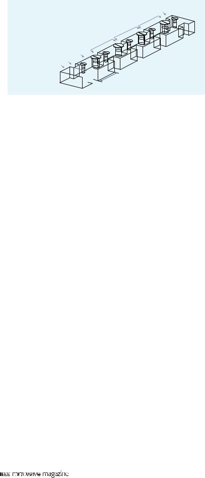
The first example under consideration is a simple implementation of a direct-coupled cavity filter in rectangular waveguide technology, which is composed of waveguide cavities coupled through thick inductive irises (see Figure 2). This waveguide topology implements the classic half-wave prototype, where the
62 |
October 2007 |
coupling windows act as the required impedance |
on a standard personal computer (Pentium IV plat- |
||||||||||||
inverters, and the waveguide cavities loaded with their |
form at 3 GHz with 1-GB of RAM). This reduced com- |
||||||||||||
input and output irises are equivalent to the half-wave- |
putational effort has allowed the employment of opti- |
||||||||||||
length transmission lines [33]. In this filter implementa- |
mization algorithms, which typically require the |
||||||||||||
tion, only one mode resonates in each single cavity, and |
repeated use of the simulation tool. |
|
|
|
|||||||||
therefore the degree of the reflection coefficient (S11 |
|
|
A prototype of this tuneable inductive waveguide fil- |
||||||||||
parameter) is equal to the number of cavities. It is also |
ter has also been manufactured. As is shown in Figure 4, |
||||||||||||
interesting to note that these filters can be employed for |
the filter is composed of two pieces: an inductive base |
||||||||||||
both narrow-band and wide-band applications [32]. |
|
structure with the thick irises and cavities and a top |
|||||||||||
To manufacture these waveguide filters, several fab- |
including the tuning screws. Once the two pieces are |
||||||||||||
rication techniques involving different degrees of accu- |
assembled, the designed filter is recovered. Starting from |
||||||||||||
racy and economic costs can be employed. Satellite |
the values provided by the CAD tool for the depths of |
||||||||||||
applications demand very high-precision components, |
the screws, they have been slightly adjusted to obtain the |
||||||||||||
where dimension tolerances are usually required to be |
desired responses in the laboratory. Experimental mea- |
||||||||||||
below 10 μm. For such purposes, spark eroding or elec- |
surements have confirmed the wide tuning range |
||||||||||||
tro-forming seems more appropriate, but they are usu- |
(between 11 and 13 GHz) of the four-pole 300 MHz |
||||||||||||
ally expensive techniques. On the other hand, low-cost |
bandpass response. |
|
|
|
|
|
|||||||
manufacturing methods, such as computer-controlled |
|
Recently, the advancements in the area of electromag- |
|||||||||||
milling or die-casting, typically introduce rounded cor- |
netic analysis tools can be used to avoid including post- |
||||||||||||
ners either in the H- or in the E-plane of the filters [9], |
assembly tuning screws when low-cost manufacturing |
||||||||||||
which can perturb the electrical response |
|
|
|
|
|
|
|
|
|
|
|
||
even beyond the specifications. |
|
|
|
|
|
|
|
|
|
|
|
|
|
A first attempt |
to overcome |
the cited |
|
|
0 |
|
|
|
|
|
|
|
|
drawback of low-cost manufacturing tech- |
|
|
|
|
|
|
|
|
|
|
|||
|
|
|
|
|
|
|
|
|
|
|
|||
niques consists on the use of tuning screws, |
|
|
|
|
|
|
|
|
|
|
|
||
as it is shown in Figure 2. If second-order |
|
−10 |
|
|
|
|
|
|
|
|
|||
effects are neglected, it can be assumed that |
|
|
|
|S21| |
|
|
|
|
|
|
|
||
the screws located in the coupling windows |
|
−20 |
|
|
|
|
|
|
|
||||
|
|
|
|
|
|
|
|
|
|||||
mainly provide the specified bandwidth of |
|
|
|
|S11| |
|
|
|
|
|||||
dB |
|
|
|
|
|
|
|
|
|||||
the electrical response, whereas the screws |
|
|
|
|
|
|
|
|
|
|
|||
|
−30 |
|
|
|
|
|
|
|
|
||||
placed in the cavities are adjusted to tune |
|
|
|
|
|
New CAD Tool |
|||||||
|
|
|
|
|
|
|
|||||||
the bandpass response at the right center |
|
|
|
|
|
|
|
FEM |
|
|
|||
frequency. Proceeding in this way, a four- |
|
−40 |
|
|
|
|
|
|
|
|
|||
pole inductively coupled rectangular wave- |
|
|
|
|
|
|
|
|
|
|
|
||
guide filter with a bandpass response of 300 |
|
−50 |
|
|
|
|
|
|
|
|
|||
MHz, tuneable in the range between 11 and |
|
|
10.5 |
10.6 10.7 |
10.8 |
10.9 |
11 |
11.1 11.2 |
11.3 |
11.4 |
11.5 |
||
13 GHz with real screws, has been success- |
|
|
|
|
|
|
GHz |
|
|
|
|
||
fully designed. |
|
|
|
|
|
|
|
|
(a) |
|
|
|
|
Following the |
automated |
procedure |
|
|
0 |
|
|
|
|
|
|
|
|
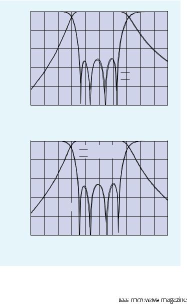
described in [38], our CAD tool has provid- |
|
|
|
|
New CAD Tool |
|
|
|
|||||
ed the geometrical dimensions of the chosen |
|
|
|
|
|
|
|
|
|||||
|
|
|
|
|
FEM |
|
|
|
|
||||
design parameters. In principle, the widths |
|
−10 |
|
|
|
|
|
|
|||||
|
|
|
|
|
|
|
|
|
|||||
of the coupling windows and the lengths of |
|
|
|
|S21| |
|
|
|
|
|
|
|
||
the cavities of the filter (see Figure 2) have |
|
|
|
|
|
|
|
|
|
|
|||
|
−20 |
|
|
|
|
|
|
|
|
||||
been optimized for providing a basic induc- |
|
|
|
|
|
|
|
|
|
||||
dB |
|
|
|
|
|
|
|
|
|
|
|||
tive-iris geometry whose bandpass response |
|
|
|
|
|
|
|
|
|
|
|||
|
−30 |
|
|
|
|
|
|
|
|
||||
can be tuned by means of the screws. Then, |
|
|
|
|
|
|
|
|
|
||||
the penetration depths of the complete set of |
|
|
|
|
|S11| |
|
|
|
|
|
|
||
tuning screws have been determined to |
|
−40 |
|
|
|
|
|
|
|
|
|||
recover the desired electrical response at 11 |
|
|
|
|
|
|
|
|
|
|
|
||
and 13 GHz (see Figure 3). In such figure, |
|
−50 |
|
|
|
|
|
|
|
|
|||
our simulated results are successfully com- |
|
|
|
|
|
|
|
|
|
||||
|
|
12.5 |
12.6 12.7 |
12.8 |
12.9 |
13 |
13.1 13.2 |
13.3 |
13.4 |
13.5 |
|||
pared with those provided by the commercial software Ansoft HFSS, based on the finite element method (FEM). The complete set of simulated results (150 frequency points) have been obtained in only 2.6 min
October 2007 |
63 |
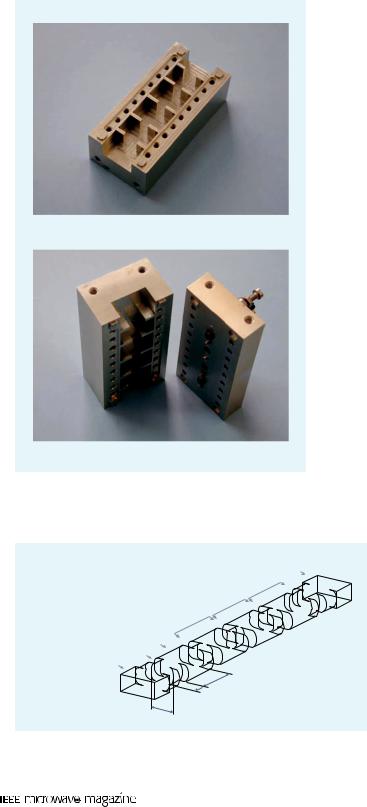
techniques are used. For such purposes, the rounded corners effects introduced in the H- or E-plane of the manufactured waveguide filters have been rigorously considered during the analysis and design stages (see details in [9]). An alternative application of the low-cost milling technique produces rounded corners in the cross section of the waveguides, as shown in Figure 5. Making use of this novel topology, a four-pole inductive filter with a
(a)
bandpass response of 300 MHz centered at 11 GHz has been completely designed as proposed in [23].
In this case, the CAD tool employed has optimized the lengths of the coupling windows and cavities of the filter (see such parameters in Figure 5). This choice has widely increased the numerical efficiency of the complete design procedure, since the optimization of the length parameters does not imply any change in the cross section of the rounded corner waveguides. Therefore, the modal chart of such arbitrarily shaped waveguides does not need to be recomputed at each optimization step. Once the lengths of all involved waveguides have been determined, a prototype has been manufactured using this alternative fabrication technique. As shown in Figure 6(a), the filter is composed of several pieces, which must be cascaded to build up the complete structure. To minimize the additional losses introduced by this fabrication technique as much as possible, the junction of consecutive pieces takes place at the half plane of each waveguide resonator.
For validation purposes, the simulated results provided by our CAD tool at the design point are successfully compared with measurements of the manufactured prototype in Figure 6(b). In this case, and using the same personal computer employed in the previous example, a global effort of 204 s has been required for obtaining the simulated results in the whole frequency band (1,000 points). Therefore, it is also concluded that the complete design procedure of this filter has been performed in reasonable development times.
E-Plane Metal Insert Filters
|
E-plane metal insert technology is another classical |
|
|
implementation of direct-coupled cavity filters, which |
|
|
has been widely employed in several microwave and |
|
(b) |
millimeter-wave applications for over 25 years [41], |
|
Figure 4. Manufactured prototype of the tuneable wave- |
[42]. In this filter configuration, the impedance inverter |
|
constants of the half-wave prototype are synthesized |
||
guide filter: (a) inductive base structure and (b) top with |
through the thin metal fins inserted in the mid plane of |
|
tuning screws. Courtesy of ESTEC, ESA. |
waveguide resonators. The geometry of a standard |
|
|
||
|
|
implementation of an E-plane filter in rectan- |
|
|
gular waveguide technology is shown in |
Output Waveguide |
|
Figure 7(a). These filters, which are usually |
Fourth Section |
|
composed of single-mode resonating cavities, |
Third Section |
|
have been proved to be suitable for low and |
Second Section |
|
moderate electrical requirements [41]. |
Resonant Cavity |
|
One advantage of this filtering technology |
|
is related to its easy manufacturing process, |
|
Coupling Window |
|
|
|
which is very suitable for low-cost and mass |
|
Input Waveguide |
|
|
l1 |
|
production. The rectangular waveguide hous- |
|
ing is initially made of two symmetrical split |
|
t1 |
|
|
w1 |
|
blocks, and then a metal sheet with all the |
|
|
|
|
|
septa is inserted longitudinally between the |
Figure 5. Inductive filter with rounded corners in the cross section of |
two blocks. In this technology, the electrical |
|
the waveguides. |
|
response of the filters is mainly controlled by |
64 |
|
October 2007 |
the pattern of the E-plane metal fins. The fabrication of |
one. Finally, it is convenient to note that our simulated |
||||||||||||||
the metal insert can be performed in several ways, for |
results are in good agreement with both numerical |
||||||||||||||
instance using metal etching or stamping methods for |
(FEM) and measured data included also in Figure 8(b), |
||||||||||||||
thicker sheets, or photolitographic and electro-deposi- |
and that a CPU time of 0.35 s was required to get the |
||||||||||||||
tion techniques if the sheet is thinner (typically below |
response per frequency point in the same computer of |
||||||||||||||
100 μm). Nevertheless, for an accurate design of these |
previous cases. |
|
|
|
|
|
|
|
|
|
|||||
filters, the metal thickness should be considered in the |
Dual-Mode Waveguide Filters |
|
|
|
|
||||||||||
electromagnetic analysis tool. |
|
|
|
|
|
|
|
||||||||
To validate this technology, a simple two-pole E-plane |
Dual-mode waveguide filters have been widely |
||||||||||||||
filter in rectangular waveguide technology providing a |
employed in satellite communication systems since |
||||||||||||||
bandpass response in the X band (between 8.34 and 8.92 |
their introduction in the early 1970s [44], [45], due to |
||||||||||||||
GHz) has been designed. As shown in Figure 7(a), the |
their well-known advantages of reduced mass and vol- |
||||||||||||||
design parameters optimized by our CAD tool have |
ume. In these structures, each waveguide resonator sup- |
||||||||||||||
been the lengths of the metal fins and of the waveguide |
ports two orthogonal degenerate modes, thus reducing |
||||||||||||||
resonators. The simulated results of the E-plane filter |
the number of cavities by a factor of two with regard to |
||||||||||||||
compare well to FEM-based HFSS data in Figure 7(b). |
single-mode resonator filters. Dual-mode filters can also |
||||||||||||||
Since the analysis of this example only involves rectan- |
implement nonadjacent couplings between resonators, |
||||||||||||||
gular waveguides of different cross section, the related |
resulting in more complex filtering functions (i.e., with |
||||||||||||||
CPU effort can be considered practically negligible. |
|
|
finite-frequency transmission zeros), typically providing |
||||||||||||
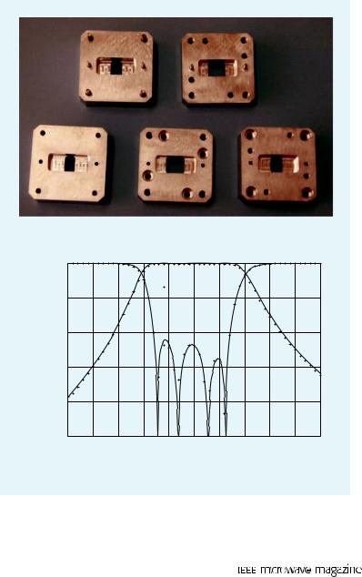
In practical applications, standard E- |
|
|
|
|
|
|
|
|
|
|
|
|
|
|
|
plane rectangular waveguide filters are |
|
|
|
|
|
|
|
|
|
|
|
|
|
|
|
revealed to offer narrow stopband per- |
|
|
|
|
|
|
|
|
|
|
|
|
|
|
|
formance as well as moderate attenua- |
|
|
|
|
|
|
|
|
|
|
|
|
|
|
|
tion slopes. To overcome such draw- |
|
|
|
|
|
|
|
|
|
|
|
|
|
|
|
backs, the number of resonators are |
|
|
|
|
|
|
|
|
|
|
|
|
|
|
|
typically increased, thus providing |
|
|
|
|
|
|
|
|
|
|
|
|
|
|
|
bulky devices not suitable for space |
|
|
|
|
|
|
|
|
|
|
|
|
|
|
|
applications. An alternative solution is |
|
|
|
|
|
|
|
|
|
|
|
|
|
|
|
based on periodic structures, which |
|
|
|
|
|
|
|
|
|
|
|
|
|
|
|
have been reported to offer improved |
|
|
|
|
|
|
|
|
|
|
|
|
|
|
|
stopband performance and reduced |
|
|
|
|
|
|
|
|
|
|
|
|
|
|
|
physical size due to well-known slow- |
|
|
|
|
|
|
|
|
|
|
|
|
|
|
|
wave effects. Recently, a periodic E- |
|
|
|
|
|
|
|
|
|
|
|
|
|
|
|
plane filter, where the rectangular |
|
|
|
|
|
|
|
|
|
|
|
|
|
|
|
waveguide resonators are periodically |
|
|
|
|
|
|
|
|
|
|
|
|
|
|
|
loaded with reactive obstacles in form |
|
|
|
|
|
|
|
(a) |
|
|
|
|
|
|
|
of ridges, has been proposed [43]. The |
|
|
|
|
|
|
|
|
|
|
|
|
|
|
|
|
|
|
|
|
|
|
|
|
|
|
|
|
|
|
|
topology of this novel periodic struc- |
|
0 |
|
|
|
|
|
|
|
|
|
|
|
|
|
ture can be seen in Figure 8(a). |
|
|
|
|
|
|
|
|
|
|
|
|
|
|
|
|
|
|
|
|
|
New CAD Tool |
|
|
|
|
|||||
|
|
|
|
|
|
|
|
|
|
|
|||||
With the aim of proving the features |
|
|
|
|
|
|
|
|
|
|
|
||||
|
−10 |
|
|
|
|
|
Measurements |
|
|
|
|
||||
of the periodic structure just described, |
|
|
|
|
|
|
|
|
|
|
|
|
|
|
|
the same passband response obtained |
|
|
|
|S21| |
|
|
|
|
|
|
|
|
|
|
|
with the previous standard E-plane filter |
|
−20 |
|
|
|
|
|
|
|
|
|
|
|
||
|
|
|
|
|
|
|
|
|
|
|
|
|
|
||
can be obtained with the periodically |
|
|
|
|
|
|
|
|
|
|
|
|
|
|
|
dB |
|
|
|
|
|
|
|
|
|
|
|
|
|
|
|
loaded solution, as it can be seen in |
|
|
|
|
|
|
|
|
|
|
|
|
|
|
|
|
−30 |
|
|
|
|
|
|
|
|
|
|
|
|
|
|
Figure 8(b). For such purposes, the CAD |
|
|
|
|
|
|
|
|
|
|
|
|
|
|
|
|
|
|
|
|
|
|
|
|
|
|
|
|
|
|
|
tool has optimized the geometrical para- |
|
|
|
|
|
|S11| |
|
|
|
|
|
|
|
|
|
meters of the metal insert shown in |
|
−40 |
|
|
|
|
|
|
|
|
|
|
|
|
|
Figure 8(a). Comparing now the out-of- |
|
|
|
|
|
|
|
|
|
|
|
|
|
|
|
band responses of both E-plane filters, it |
|
−50 |
|
|
|
|
|
|
|
|
|
|
|
|
|
can be concluded from Figures 7(b) and |
|
|
|
|
|
|
|
|
|
|
|
|
|
|
|
|
10.5 |
10.6 |
10.7 |
10.8 |
10.9 |
11 |
11.1 |
11.2 |
11.3 |
11.4 |
11.5 |
||||
|
|
||||||||||||||
8(b) that the periodic solution response has better selectivity and wider stopband than the standard counterpart. Regarding the total length of both solutions, the complete periodic filter is roughly 50% shorter than the standard
October 2007 |
65 |
improved selectivity and insertion loss performance. Such electrical responses have been traditionally required by narrow-band channel filters [44], [45].
For implementing dual-mode filters, square and circular waveguides have been typically used [2], since they support the dominant mode in vertical and horizontal polarizations. To understand the operation of these compact filtering devices, a classical implementation using square waveguide cavities and tuning screws has been first considered, whose topology is shown in Figure 9(a). The screws rotated 45◦ are used for controlling the coupling levels between the two orthogonal modes of each cavity, whereas the other screws allow the independent frequency tuning of each resonant mode. The required intercavity coupling levels between each pair of resonant modes are performed through an evanescent rectangular waveguide. The same kind of rectangular iris is also employed for coupling the input and output waveguides to the corresponding square cavities. As shown in Figure 9(a), the orientations of the two modal coupling screws are perpendicular, which realizes a modified elliptic-function response with two transmission zeros [44].
The dual-mode filter topology described above has been used to obtain a four-pole bandpass response of 400 MHz bandwidth centered at 15 GHz with two transmission zeros. For such purposes, our CAD tool has optimized the lengths of all waveguides, the width and height of the central rectangular iris, and the penetration depths of the tuning screws. In Figure 9(b), we successfully compare our simulated results for the designed filter with the numerical data generated by the FEM-based Ansoft HFSS code. The same personal computer used in the previous examples was employed to generate these results (150 frequency points), with a global CPU effort of 229 s.
It is widely recognized that the use of tuning screws in dual-mode filters can severely affect their power handling capability as well as increase the passive intermodulation risks. These restrictions are relevant for dual-mode components, which are typically used as channel filters in output multiplexers of satellite payloads. For such reasons, some novel topologies of dualmode filters without tuning screws, based on rectangular (almost square) [46], [47], circular [48] and elliptical [49] resonators, were proposed during the 1990s. A
|
|
|
|
t |
|
b |
|
|
|
|
|
|
Ls1 |
Lr1 |
Ls2 |
Lr2 |
Ls3 |
b |
|
|
|
|
|
|
|
|
(a) |
|
|
|
0 |
|
|
|
|
|
−10 |
|
|S21| |
|
|
|
|
|
|
|
|
|
−20 |
|
|
|
|
dB |
−30 |
|S11| |
|
|
|
|
|
|
|
||
|
−40 |
|
|
|
|
−50 |
|
New CAD Tool |
|
|
|
|
|
FEM |
|
|
|
|
|
|
|
|
|
|
|
|
−608 |
9 |
10 |
11 |
12 |
13 |
14 |
GHz
(b)
Figure 7. Standard E-plane filter in rectangular waveguide technology: (a) 3-D geometry and 2-D view of the metal insert and (b) scattering parameters.
t
b
Ls1 |
Lr1 |
Ls2 |
Lr2 |
Ls3 |
|||||
|
|
|
|
|
|
|
|
|
|
b |
s1 s2 l2 |
l1 |
s1 s2 l2 |
l1 |
|
|
|
|
(a) |
|
|
|
|
0 |
|
|
|
|
|
|
|
−10 |
|
|
|
|
|
|
|
−20 |
|
|
|S21| |
|
|
|
dB |
−30 |
|S11| |
|
|
|
|
|
|
|
|
|
|
|
||
|
−40 |
|
New CAD Tool |
|
|
|
|
|
|
|
|
|
|
||
|
−50 |
|
FEM |
|
|
|
|
|
|
Measurements |
|
|
|
||
|
|
|
|
|
|
||
|
−60 |
9 |
10 |
11 |
12 |
13 |
14 |
|
8 |
||||||
|
|
|
|
GHz |
|
|
|
|
|
|
|
(b) |
|
|
|
Figure 8. Periodically loaded E-plane waveguide filter:
(a)3-D geometry and 2-D view of the metal insert and
(b)scattering parameters.
66 |
October 2007 |

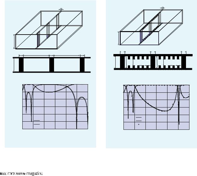
practical realization of a dual-mode filter in circular waveguide technology without tuning screws is presented in Figure 10, where it can be noticed that only elliptical irises are used.
Each cavity of the dual-mode filter shown in Figure 10 contains two elliptical irises, the first one rotated 45◦ for realizing the modal coupling of the two degenerate modes and the second one (not rotated) with major and minor axis dimensions chosen for tuning each independent resonant frequency. The cross section of a central elliptical iris is also designed for recovering the needed coupling levels between the pairs of resonant modes placed at adjacent cavities. Finally, the input and output waveguides are coupled to the first and last waveguide resonators, respectively, through two elliptical irises. For designing this filter, the dimensions of all elliptical irises, as well as the lengths of the circular cavities, have been determined.
In this case, our flexible CAD tool has been used to provide a four-pole elliptical bandpass response of 2% relative bandwidth centered at 11 GHz. For generating the two transmission zeros of such electrical response, the modal coupling elliptic irises of the filter must be orthogonally oriented, as it is shown in Figure 10. Once the geometrical dimensions of the designed dual-mode filter were determined, a real prototype was manufactured. In Figure 11(a) we can see the pieces of the filter, which include the required elliptical irises and circular waveguide cavities. After assembling all these pieces, a very compact filtering structure is finally obtained for space applications. An excellent comparison between the measurements of the fabricated filter response and the predicted simulated results is offered in Figure 11(b). It is relevant to remark that such experimental results were obtained without using any tuning screw in the prototype, which was possible due to the accuracy of the manufacturing technique employed (i.e., spark eroding).
Evanescent Mode Waveguide Filters
of-band performance and sharp selectivity. In addition, these filters are very competitive in terms of mass and volume due to their below-cutoff waveguide housing. As a practical example, we have used this compact geometry to realize a seven-pole bandpass response of 250 MHz bandwidth centered around 7 GHz. The design parameters determined by our CAD tool were the lengths of the evanescent waveguide sections and of the ridge waveguides (see Figure 12), whereas the housing dimensions and the ridge width and height were previously fixed for optimizing the filter length
Frequency |
Coupling |
Output |
|
Iris |
|||
Tuning |
Waveguide |
||
|
Input
Waveguide
Modal Coupling Screw
|
(a) |
|
0 |
|
|
|
New CAD Tool |
|
−10 |
FEM |
|
|
|
|
−20 |
|
|S11| |
dB |
|
|
−30 |
|S21| |
|
|
|
|
−40 |
|
|
−50 |
|
15 15.2 15.4 15.6 15.8 16 |
14 14.2 14.4 14.6 14.8 |
||
|
|
GHz |
|
|
(b) |
Another compact implementation of filtering structures for space applications is based on evanescent mode waveguides, whose typical configuration using symmetrical metal ridges can be seen in Figure 12. These filters, originally proposed in [50] and [51] and refined in
[52], are essentially composed of a hollow below |
|
|
cut-off waveguide housing, which transmits the |
Output Waveguide |
|
energy between standard waveguide access ports |
Second Section |
|
through shunt capacitive elements (ridges in |
||
Coupling Iris |
||
Figure 12). The below cut-off waveguide sections |
||
placed between consecutive ridges can be modeled |
Frequency Tuning Iris |
|
Modal Coupling Iris |
||
as impedance inverters and shunt inductances |
||
Input Coupling Iris |
||
that, when combined with the cited capacitances, |
||
Input Waveguide |
||
provide the required filter resonances. |
|
|
Evanescent mode waveguide filters are a good |
|
|
choice for the input and output stages of satellite |
|
|
payloads, since they can provide moderate and |
Figure 10. Dual-mode filter in circular waveguide technology with- |
|
wide-band electrical responses with excellent out- |
out tuning screws. |
October 2007 |
67 |
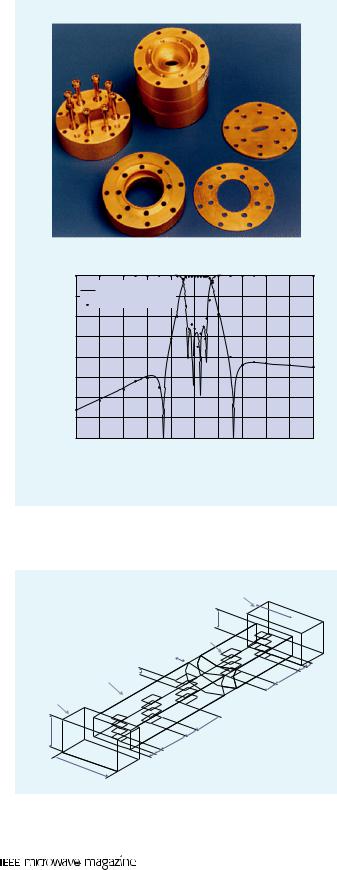
and its stopband behavior. A prototype of the designed filter was manufactured using a conventional milling technique. As shown in Figure 13(a), the structure is composed of two symmetrical pieces including the cor-
|
|
|
|
(a) |
|
|
|
|
0 |
|
|
|
|
|
|
|
−10 |
New CAD Tool |
|
|
|
||
|
Measurements |
|
|
|
|||
|
−20 |
|
|
|
|||
|
|
|
|
|
|
|
|
|
−30 |
|
|
|
|
|
|
dB |
−40 |
|S |
|
| |
|
|S11| |
|
|
−50 |
21 |
|
|
|||
|
|
|
|
|
|
||
|
−60 |
|
|
|
|
|
|
|
−70 |
|
|
|
|
|
|
|
−80 |
10.2 10.4 10.6 10.8 |
11 |
11.2 11.4 11.6 11.8 |
12 |
||
|
10 |
||||||
|
|
|
|
|
GHz |
|
|
|
|
|
|
|
(b) |
|
|
Figure 11. Manufactured prototype of the dual-mode filter in circular waveguide technology: (a) view of the internal pieces and (b) scattering parameters. Courtesy of ESTEC, ESA.
responding metal ridges, which must be assembled together to build up the complete filter.
The experimental measurements of the manufactured prototype are included in Figure 13(b), where they compare well with the simulated results of the designed structure. Nevertheless, some slight variations between both responses are observed in the passband, which are attributed to manufacture tolerances. For this structure, small perturbations in the penetration depths of the upper and lower metal inserts seriously affect the ridge gap dimension, which is identified to be a very sensitive parameter. Additionally, slight assembly misalignments can easily spoil the required symmetry of this filter design. To overcome such drawbacks, a potential alternative consists of using an asymmetrical configuration, with metal inserts placed only in one wall of the
waveguide housing.
A practical implementation of an asymmetrical evanescent mode waveguide filter, which uses tuning screws instead of rectangular cross-section metal ridges, is shown in Figure 14(a). In these structures, the use of post-assembly tuning screws can also be useful for overcoming response degradations due to manufacture tolerances. Using this asymmetrical configuration, a Chebyshev bandpass electrical response with five poles, 300 MHz bandwidth, and center frequency of 10 GHz was realized. For such purposes, the CAD tool optimized the penetration depths of the screws, as well as the lengths of below-cutoff waveguide sections placed between such screws.
In Figure 14(b), we successfully compare the simulated results provided by our CAD tool for the designed asymmetrical filter with numerical data, obtained with Ansoft HFSS based on the FEM method. To compute our simulated results (200 frequency points) with the same personal computer of previous cases, a CPU time of 35 s was only needed, which was very suitable for design purposes.
Output Waveguide
|
|
ah |
|
|
|
bh |
|
|
Metal Ridge |
|
|
Waveguide |
|
w |
|
h |
|
ln+1 |
|
Housing |
t |
||
Input |
|
n |
|
|
ln |
||
Waveguide |
|
|
|
|
tn–1 |
|
|
bin |
|
l3 |
|
|
|
t2 |
|
|
t |
l2 |
|
ain |
l1 |
1 |
|
|
|
|
|
Figure 12. Symmetrical evanescent mode waveguide filter with centered ridges.
Conclusions
All-metal waveguide filters have been widely used in satellite payloads since the advent of the first space communication systems four decades ago. In this period, such technology has been continuously evolving due to the increasing requirements demanded to these components. This article has tried to describe this historical evolution, and its theoretical and technological features. Special attention has also been paid to present the most recent advances in the development of CAD tools for satellite filters, which are based on full-wave electromagnetic analysis methods.
Several practical examples of waveguide filters for space communication systems were considered. For each waveguide filter type, we
68 |
October 2007 |

|
|
|
|
(a) |
|
|
|
|
|
0 |
|
|
|S21| |
|
|
|
|
|
−10 |
|
|
|
|
|
|
|
|
|
|
|
|
|
|
|
|
|
−20 |
|
|
|S11| |
|
|
|
|
|
−30 |
|
|
|
|
|
|
|
dB |
−40 |
|
|
|
|
|
|
|
|
−50 |
|
|
|
|
|
|
|
|
−60 |
|
New CAD Tool |
|
|
|
||
|
−70 |
|
|
|
|
|||
|
|
Measurements |
|
|
|
|||
|
−80 |
|
|
|
|
|||
|
6.85 |
6.9 |
6.95 |
7 |
7.05 |
7.1 |
7.15 |
|
|
6.8 |
|||||||
|
|
|
|
GHz |
|
|
|
|
|
|
|
|
(b) |
|
|
|
|
Figure 13. Manufactured prototype of the evanescent mode filter: (a) view of the two symmetrical pieces with ridges and (b) scattering parameters. Courtesy of Alcatel Alenia Space (Spain).
have described a standard configuration, its typical electrical response, and the potential use within a satellite communications payload. Then, we presented some of the technological novelties related to each filter category under study. The two first examples included in this article are classical implementations of direct-coupled cavity filters, i.e., the inductively coupled rectangular waveguide filter and the E-plane metal insert filter. For both of them, standard topologies and common manufacturing processes were outlined. In the case of inductive filters, we have also shown how modern CAD tools can cope with the undesired mechanization effects due to low-cost mass-production techniques. For the E-plane technology, a more compact alternative solution with an improved stopband electrical performance was proposed. Later on, the concept of dual-mode filters was introduced. Two solutions, the first one based on square waveguide cavities and tuning screws and the second one using circular cavities and elliptical irises without tuning elements, were detailed. Finally, we focused on compact solutions for the input and out-
|
|
Output Waveguide |
|
Waveguide Housing |
|
Input |
Tuning Screw |
|
Waveguide |
|
|
|
|
h3 |
|
h1 |
h2 |
|
l3 |
|
|
|
l2 |
|
|
l1 |
|
|
(a) |
0 |
|
|
New CAD Tool |
−10 |
FEM |
|
−20 |
|S21| |
|
|
|
|
dB |
|
|
|
|
||
−30 |
|
|
|
|
|
|
|
|
|
|
|
|
|
|
−40 |
|
|
|
|
|S11| |
|
|
|
|
|
|
|
|
−50 |
|
|
|
|
|
|
9.5 |
9.6 |
9.7 |
9.8 |
9.9 |
10 10.110.210.310.410.5 |
|
|
|
|
|
GHz |
|
|
|
|
|
|
(b) |
|
Figure 14. Asymmetrical evanescent mode waveguide filter with tuning screws: (a) geometry and (b) scattering parameters.
put stages of satellite payloads, thus considering the evanescent mode waveguide filter technology.
Acknowledgments
The authors would like to thank ESTEC, ESA (in particular Dr. Marco Guglielmi) and Alcatel Alenia Space (Spain) for providing the manufactured prototypes shown in the manuscript. They also want to acknowledge their research colleagues and Ph.D. students at Valencia (Spain), who have contributed with some of the numerical and experimental results included in this article.
References
[1]G. Maral and M. Bousquet, Satellite Communication Systems, 3rd ed. Chichester: Wiley, 1998.
[2]C. Kudsia, R.J. Cameron, and W.-C. Tang, “Innovations in microwave filters and multiplexing networks for communications satellite systems,” IEEE Trans. Microwave Theory Tech., vol. 40, no. 6, pp. 1133–1149, Jun. 1992.
[3]R. Coirault, S.J. Feltham, G. Gatti, G. Guglielmi, and D. Perring, “Overview of microwave components activity at the European Space Agency,” IEEE Trans. Microwave Theory Tech., vol. 40, no. 6, pp. 1150–1158, Jun. 1992.
[4]G.L. Matthaei, L. Young, and E.M.T. Jones, Microwave Filters, Impedance-Matching Networks and Coupling Structures. New York: McGraw-Hill, 1964.
[5]J. Uher, J. Bornemann, and U. Rosenberg, Waveguide Components for Antenna Feed Systems: Theory and CAD. Norwood: Artech House, 1993.
[6]C. Kudsia, “A light weight graphite fiber epoxy composite (GFEC) waveguide multiplexer for satellite applications,” in Proc. 4th Eur. Microwave Conf., Montreaux, Switzerland, Sep. 1974, pp. 585–589.
[7]J.W. Bandler, Ed., “Special Issue on Automated circuit design using electromagnetic simulators,” IEEE Trans. Microwave Theory
Tech., vol. 45, no. 5, pp. 709–866, May 1997.
October 2007 |
69 |