
Holpzaphel_-_Nonlinear-Solid-Mechanics-a-Contin
.pdf

120 3 The Conce.pt of Stress
(compare with eq. (l.166)). In order to obtain the eigenvalues we must solve the characteristic polynomial-of u, which is cubic in 1\:., i.e.
(3.38)
with the three principal stress invariants lu of tensor u (com.pare with eqs. (1.170)- ( 1. l72)), Le.
f..1 |
(u) = trcr = .,\~ |
+ ,,\~ + /\; |
, |
|
(3.39) |
||||
J2 |
{u) = ~- |
[{tru) |
2 |
- |
tr(cr |
2)] |
= /\7A;+ A7/\; + ,\;,\; |
, |
(3.40) |
|
|
|
|
|
|
|
|||
|
|
|
|
|
|
|
|
|
(3.4.1) |
The three eigenvalues ,,\~ are here called principal normal stresses and typically are denoted by a,1' a = The principal values ·'1a include both the maximum and
minimum normal stresses among all planes passing through a given x.
The corresponding three orthonormal e.igenvectors iia, which are then characterized through refation (3.37), are the principal directions of u. The normal stress is stationary along these principal directions. Their related norma] planes are known as principal ,planes. Since the stress tensor u is sym·metric the set of eigenvectors form a mutually orthogonal basis. Shear stress components vanish at normal (principal) planes, since obviously aH eigenvectors are normal to their respective principal planes.
We -may rep.resent u in the spectral form
3 |
|
|
u(x_, t) = L O"utln ® fiu |
(3.42) |
|
<t-=l |
|
|
(see Section 1.4), satisfying the eigenvalue problem uita |
= alliia, a = 1, 2, 3. |
Note |
that only for isotropic materials do the introduced three principal directions fia |
of u |
|
coincide with the principal directions, as defined in Section 2.6..For a brief explanation the reader is referred to Section 5.4, in particular to ·eq. (5.88), and also to Section 6.2.
Maximum .and minimum shear stresses. The next goal is to find the direction of the unit vector n at x that gives the maximum and minimum values of shear stresses·T.
In the following we choose the eigenvectors fia, a = 1, 21 3, of u as a possible set of basis vectors. Then, according to the spectral decomposition (3..42), all non-diagonal· components of the matrix [u] vanish. The components cr1 ~ a 2 , a3 form the only entries of the stress matrixT and [u] is 'diagonalized'.
The Cauchy traction vector ·tp then appears in the simple form
(3.43).:
where n = n 1n1 + n2 n2 + n:-ifi3 denotes the .unit vector normal to an arbitrary oriented_·:_ surface element. The normal stress .and shear stress on that surface element follow from:·.·,


124 |
3 The Concept of Stress |
Post-multiplying (3.52) with the unit vector n we find using rule (1.53) and (3.28)2 that
un = a(n ® n)n
=a (n · n) n =an= tll . |
(3.53) |
|
~ |
n |
|
1 |
|
|
Evidently, tll is along (or opposite) n (compare with Figure 3.4). This stress state is characterized by a normal stress a, the shear stress is zero. The stress a characterizes either pure tension (if a > 0) or pure compression (if a < 0).
Consider a rectangular Cartesian coordinate system. If a 11 = er = const and all other stress components are identically zero, then we have either uniform tension or in the x 1-direction. In the literature these stress states are often referred to as uniaxial tension and uniaxial compression, respectively. This may
be imagined as the stress in a rod (with uniform cross-section) generated by forces applied to its plane ends in the x 1-direction, which is one principal direction of stress.
A uniform tension or compression of a uniform cylindrical rod leads to a deformation, which we had already called uniform extension or compression (see p. 92).
A three-dimensional stress state in which all shear stress components vanish, i.e. aab = 0, a i= b, is said to be triaxial, while in a biaxial stress state (which is associated with biaxial deformations) we have a pair of non-vanishing normal stresses, i.e. a1, a2 ; a2 , a3 ; a 1 , a3 • However, in an equibiaxial stress state (which is associated with equibiaxial deformations) the non-vanishing normal stresses have the same value.
(ii) A pure shear stress state at a certain point is given by the stress tensor
u = r(n ® m + m ® n) |
or |
(3.54) |
(see Figure 3.5(b)). Here, the stress r |
is related to the directions of the unit vectors n |
|
and m, with property m · n = 0. |
|
|
Post-multiplying (3.54) with the unit vector n we obtain with rule (1.53) and (3.28h
un = r(n®m+m®n)n |
|
|
= r((m · n) n + (n · n) m) =rm= t;. . |
(3.55) |
|
~~ |
|
|
0 |
I |
|
Evidently, t~ is tangential to the surface and along (or opposite) m, i.e. perpendicular to n (compare with Figure 3.4). This stress state is characterized by a
T (or'" pure tangential stress) and the normal stress is zero.
Consider a rectangular Cartesian coordinate system. = a~n = T = const and
all other stress components are identically zero, then this stress state is characterized by a uniform shear stress. A state of uniform shear stress leads to a uniform (or simple) shear deformation, as illustrated in Figure 2.2 (see also Exercise 2 on p. 93 ).

3.3 |
Examples of States of Stress |
125 |
(a) |
(b) |
t~ =Tm |
|
lt~I = T
n |
n |
|
tll =an |
(c)
n
tU =-po
Figure 3.5 Examples of stress states.
(iii) A hydrostatic stress state at a certain point is given by the stress tensor
u =-vi or  (3.56)
(see Figure 3.5(c)). Within a rectangular Cartesian coordinate system that means that
we have normal stresses a 11 |
= a 22 = a33 = -p and no shear stresses on any plane |
|
containing this point, i.e. a 12 |
= a~a = a:11 = 0. |
|
Post-multiplying (3.56) with the unit vector n, we obtain, using (3.28)2, |
||
un = -(vl)n = -vn = t~! . |
(3.57) |
|
Evidently, tU is opposite to the normal vector n. The relationship un = |
-pn holds only |
|
if n is a principal direction of u. Note that any three mutually orthogonal directions may be regarded as principal directions (compare also with eq. (1.179)). This stress state is characterized by a scalar p, known as the hydrostatic pressure. In ge~eral, the hydrostatic pressure is a scalar function of time t, and in the literature is often introduced with the opposite sign.
One example of stress state (3.56) is in an (elastic) fluid (without motion) that is
not able to sustain shear stresses. Taking the trace of (3.56), we obtain
p = - |
1 |
|
1 |
|
-tru |
or |
p = - 3a"u ' |
(3.58) |
|
|
3 |
|
|
|
126 |
3 |
The Concept of Stress |
.indicating that the pressure of the (elastic) ·fluid is a mean pressure. |
||
The three stress fields described for a certain point x at .t (with u constant) corre- |
||
spond to the states, as illustrated in Fi_gure 3.5. |
||
(iv) A plane stress state at a certain point is given by the relation |
||
|
|
(359) |
and a 11 , a 22 _, a 12 |
are functions of the coordinates :z;1 .and :r.2 only. Consequently, the |
|
~r~1-direction, as represented by it3, |
is a principal direction of stress with a zero car.. |
|
responding principal stress a~i:1• The other two principal directions acting in a pfane normal .to ila are inclined at an angle fJ with the :r; 1 and x 2 direction, where
|
|
2a12 |
|
|
(3.60) |
|
|
tan2B = ---- |
|
|
|||
|
|
a1.1 - |
0"22 |
|
|
|
The corresponding maximum and minimum -stresses are given by |
|
|||||
1 |
+ 0"22) ± |
[1 |
? |
') |
] J j'> |
(3.61) |
2(0"11 |
4(0"11 - |
0"22)- + <J"j2 |
- 1 |
|||
defining a biax.ial stress state.
The maximum shear stress Tmax for a plane stress state will be the largest of the three values of (3.48}~-(3.50)2 s-ince cr:1 = 0. The planes of extremal shear stresses form angles of ±45° with the .planes of the principal stresses.
A plane -stress state occurs at any unloaded surface in a continuum body and is of practical interest.
EXERCISES
I. For the case of plane stress, show that -e-q. (3.38) reduces to eq. (3.61 ).
2~ Assume a plane stress state in a rectangular cube bounded by the planes :r:1
±a, :I:2 = ±b, :1;3 = ±c .. The state of stress at a po.int with coordinates ;1~1 , ~r:2, :1::1 in the cube is given by
where n, /3 are constants. For a point with-coordinates (a/2, -b/2,-0), determ:ine.
(a)the principal normal .stresses and the associated principal directions,
(b)the planes_, characterized by the unit normal n_, that give the maximum and minimum shear stresses and the magnitude of the extremal shear stress.
(c)Find the total Cauchy traction vector on each face of this rectangular cube.
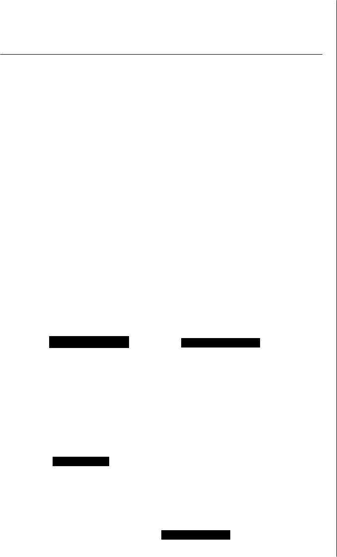
3.4 AHernative Stress Tensors |
127 |
3.4 Alternative Stress Tensors
Numerous definitions and names of stress tensors have been proposed in the literature. Each definition has advantages .and disadvantages. In the following we discuss stress tensors used for practical nonlinear analyses ..Most of their components do not have a direct physical interpretation.
Often it is convenient to work with the so-called Kirchhoff stress tensor r, which differs from the Cauchy stress tensor by the volume ratio J. It is a contravariant spatial tensor field parameterized by spatial coordinates, and is defined by
T =Ju or Tut> = ,Ja ab • (3.62)
We introduce further the second Piola-Kirchhoff stress tensor S which does not admit a physical .interpretation in terms of surface tractions. The contravariant material tensor field is symmetric .and parameterized by material coordinates. Therefore, .it often represents a very useful stress measure in computational mechanics and in the formu- lation of constitutive equations, in particular, for solids., as we will see in Chapter 6.
. The second Piola-Kirchhoff stress tensor is obtained by the pull-back operation on the contravariant spatial tensor field T~ by the motion x, which is, according to (2.85h,
or |
1 -lp-l |
(3.63) |
SA H = FAu 1Jb Tub • |
||
Hence, the Kirchhoff stress tensor is the push-forward of S, i.e.~ using (2.85}1, |
|
|
or |
|
(3.64) |
Using eqs. (3.6.3)2, (3.62) and (3.8) we obtain the Piola transformation relating the two stress fields S and u, i.e..
S == .IF-tuF-T = F- 1p =ST
or |
S |
|
JF-t |
- tF - l |
|
|
p-lp |
= |
c |
(3.65) |
||
|
|
|
|
|||||||||
|
|
A 0 |
= ~ . An · ~I.lb |
fTub |
= ·Aa |
n IJ |
•.J II A |
|
||||
with its inverse, |
|
|
|
|
|
|
|
|
|
|
|
|
|
|
|
|
or |
1-'ub - |
' |
|
uA .t'.bJJ' A.IJ • |
(3.66) |
|||
|
|
|
|
|
rr |
- |
|
7- l F. |
.'fi' |
S . |
|
|
From eq. (3.65) we find a fundamental relationship between the first Piola-Kirchhoff stress tensor P introduced in (3.8) and the symmetric second Piola-Kirchhoff stress tensor S, i.e.
P= FS or |
(3.67) |
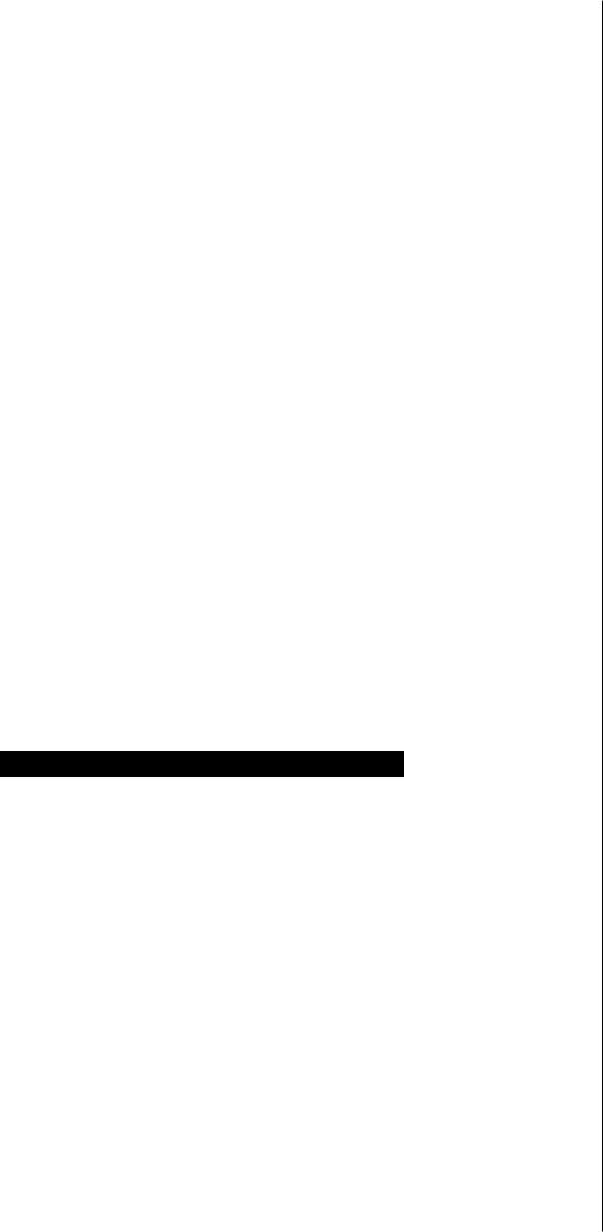
128 3 ·The Concept of Stress
In addition to the four stress tensors -given above, we .introduce another important -quantity. .It ·is a material stress tensor formally defined as
Tn = .RTP or  (3.68)
The non-symmetric tensor Tu, which -is not in general positive definite, is known as the Biot .stress tensor. With (3.67) and the polar decomposition F = RU we deduce from (3.68) that Tn = RT (FS) = US. Herein, R and U denote the rotation tensor (with defR = 1) and the (positive definite) symmetric right stretch tensor, respectively.
They are according to the polar decomposition of the deformation gradient F (see Sec-
tion 2~6).
Multiplying eq. (3.68) by R from the left-hand side, we obtain the polar decompo-
s.ition |
|
|
P=RTn |
or |
(3.6.9) |
for the first Piola-Kirchhoff stress tensor, which is in analogy with that for F. Since the .Biot stress tensor Tn is not positive definite this decomposition .is not unique, in general.
Other examples of stress tensors are the symmetric so..called corotated Cauchy stress tensor uu, as introduced by Green and Naghdi, and the Mande·J stress tensor
~ which is in general not symmetric. These tensors are defined with respect to an intermediate configuration. In .order to obtain the corotated Cauchy stress tensor take relation (3.66) .and use the symmetric right stretch tensor U instead of F. Then apply relation (3.65}1 and the polar decomposition -F = RU to find
|
(3.70) |
The .Mande] stress tensor is defined to be |
|
E =CS |
(3.71) |
which is often used to describe .inelastic (plastic) materials.
EXERCISES
l.Consider an infinitesimal resultant (pseudo) force dfn = (TnN)dS, where TnN denotes the Biot traction vec.tor. Using (3.68) and the linear transformations
(3.3)2 and (3 ..1)2, verify that
= . 'r dfn R df ,
which shows that d.fn -only differs from elf (.introduced in (3 ..l )) by the rotation tensor RT.
