09.Datapaths
.pdf
Chapter 9 − Datapaths |
Page 21 of 24 |
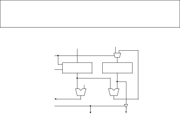
From analyzing the algorithm, we conclude that the following registers and functional units are needed in the datapath:
•One register for storing the variable product.
•One down counter with parallel load for storing the variable n and for decrementing n. The parallel load feature will allow for the input of n.
•One multiply functional unit.
•One greater-than-one comparator for returning the status signal to the control unit.
•A tri-state buffer for output.
Having decided on what components are needed in the datapath, we need to connect them together so that the functional units will get the correct data, and the outputs from the functional units will be stored in the correct register.
The complete custom datapath is shown in Figure 22. For example, in line 4 of the algorithm, one operand of the multiply function is the product and the other operand is n. Hence, the output of the register where product is stored is connected to one input of the multiply unit. Since n is stored in the counter, therefore, the output of the counter is connected to the second input of the multiply unit. The result of the multiply is assigned back into the variable product. Thus, in the datapath, we needed a connection from the output of the multiply functional unit back to the input of the register where product is stored. However, we cannot make this connection directly because we also need to load the constant 1 into this register as required by line 2 of the algorithm. So a 2-to-1 multiplexer is used to select whether the constant 1 or the output from the multiply unit gets stored in the register. The down counter allows for the execution of line 5. Since the counter also serves as the register for the variable n, we don’t need an extra register. The parallel load feature of the counter allows the execution of line 1. The tri-state buffer, connected to the output of the product register, is needed for the final output of the result. Finally, the comparator generates the status signal for the condition n > 1 to the control unit. One input to the comparator comes from the counter where n is stored and the other input is the constant 1. ♦
1input n
2product = 1
3while n > 1
4product = product * n
5n = n – 1
6output product
Figure 21. Algorithm for solving the factorial of n problem of Example 9.7.
|
Input |
"1" |
|
Load |
|
1 |
0 |
|
s |
y |
|
Count |
down counter |
register for |
|
also for storing n |
storing product |
||
|
"1" |
|
|
(n > 1) |
> |
* |
|
|
|
|
|
Done |
|
|
|
|
Done |
|
Output |
Figure 22. Dedicated datapath for solving the factorial of n problem of Example 9.7.
Microprocessor Design – Principles and Practices with VHDL |
Last updated 7/16/2003 12:32 PM |

Chapter 9 − Datapaths |
Page 22 of 24 |
9.9VHDL for a Dedicated Datapath
Figure 23 shows the VHDL code for the dedicated datapath of Figure 20.
LIBRARY ieee;
USE ieee.std_logic_1164.ALL;
USE ieee.std_logic_arith.ALL;
ENTITY Datapath IS PORT (
Clock: IN STD_LOGIC;
-- primary datapath input
Input: IN STD_LOGIC_VECTOR(7 DOWNTO 0);
--control signals Load: IN STD_LOGIC; Shift: IN STD_LOGIC; Count_e: IN STD_LOGIC; Clear: IN STD_LOGIC; Count_b: IN STD_LOGIC; Down: IN STD_LOGIC; OutDone: IN STD_LOGIC;
--status signals
Eq8: OUT STD_LOGIC;
LSBeg1: OUT STD_LOGIC;
-- primary datapath output Done: OUT STD_LOGIC; Output: OUT STD_LOGIC);
END Datapath;
ARCHITECTURE Structural OF Datapath IS
COMPONENT shiftreg PORT (
Clock: IN STD_LOGIC;
SHSel: IN STD_LOGIC_VECTOR(1 DOWNTO 0);
D: IN STD_LOGIC_VECTOR(7 DOWNTO 0);
Q: OUT STD_LOGIC_VECTOR(7 DOWNTO 0));
END COMPONENT;
COMPONENT counter PORT (
Clock: IN STD_LOGIC;
Clear: IN STD_LOGIC;
Count: IN STD_LOGIC;
Down: IN STD_LOGIC;
Q: OUT INTEGER RANGE 0 TO 15);
END COMPONENT;
SIGNAL SHSel: STD_LOGIC_VECTOR(1 DOWNTO 0);
SIGNAL ShiftOut: STD_LOGIC_VECTOR(7 DOWNTO 0);
SIGNAL CountbitOut: INTEGER RANGE 0 TO 15;
SIGNAL CounteightOut: INTEGER RANGE 0 TO 15;
SIGNAL Equal: STD_LOGIC;
SIGNAL Up: STD_LOGIC;
Microprocessor Design – Principles and Practices with VHDL |
Last updated 7/16/2003 12:32 PM |

Chapter 9 − Datapaths |
Page 23 of 24 |
|
|
|
|
|
BEGIN |
|
|
SHSel <= Shift & Load; |
|
|
U0: shiftreg PORT MAP(Clock,SHSel,Input,ShiftOut); |
|
|
LSBeg1 <= ShiftOut(0); |
|
--counteight Up <= '0';
U1: counter PORT MAP(Clock,Clear,Count_e,Up,CounteightOut); Eq8 <= '1' WHEN CounteightOut = 8 ELSE '0';
--countbit
U2: counter PORT MAP(Clock,Clear,Count_b,Down,CountbitOut); Equal <= '1' WHEN CountbitOut = 0 ELSE '0';
Output <= Equal WHEN OutDone = '1' ELSE 'Z'; Done <= OutDone;
END Structural;
Figure 23. VHDL code for the datapath of Example 9.6, Figure 20.
9.10 * Optimization for Datapaths
9.10.1 Functional Unit Sharing
asd
9.10.2 Register Sharing
asdf
9.10.3 Bus Sharing
asdf
9.11Summary Checklist
Datapath
General datapath
Dedicated datapath
Control signals
Status signals
Register-transfer level design
Control word
Timing issues. When a register is updated
Microprocessor Design – Principles and Practices with VHDL |
Last updated 7/16/2003 12:32 PM |
Chapter 9 − Datapaths
Index
C
Control signal, 2, 3
Control word, 3
D
Data transfer methods, 16 multiple destinations, 16 multiple sources, 16 tri-state bus, 17
Datapath, 2
complex example, 8
dedicated. See Dedicated datapath. general. See General datapath. simple example, 3
timing issues, 5 Dedicated datapath, 15
data transfer methods, 16 examples, 17
selecting functional units, 15 selecting registers, 15
Page 24 of 24
timing issues, 5 using a, 17
G
General datapath, 3 timing issues, 5 using a, 4
R
Register file, 8
Register transfer level, 2
RTL. See Register transfer level.
S
Status signal, 2, 5
T
Timing issues, 5
Tri-state bus, 17
Microprocessor Design – Principles and Practices with VHDL |
Last updated 7/16/2003 12:32 PM |
