

01_elektor_electronics_UK_january_2006
.pdf+5V
|
|
|
|
|
|
|
|
|
|
|
|
|
|
|
|
|
|
|
|
|
|
|
|
|
|
|
|
|
|
|
|
|
|
|
|
|
|
|
|
|
|
|
|
|
|
|
C7 |
|
C6 |
|
R12 |
|
|
|
|
|
|
|
|
|
|
|
|
||||||
|
|
|
|
|
|
|
|
|
|
|
|
|
|
|
|
|
|
|
|
|
|
|
|
|
|
|||||||||
|
|
|
|
|
|
|
|
|
|
|
|
|
4k7 |
|
|
|
|
|
|
|
|
|
|
|
|
|||||||||
+5V |
|
IC2 = 74HC4518 |
|
|
|
|
|
|
|
|
|
|
|
|
24 |
|
|
|
|
|
|
|||||||||||||
|
|
|
|
|
|
|
|
|
|
|
|
|
|
|
|
|
|
|||||||||||||||||
|
|
|
|
|
|
|
|
|
220µ |
|
16V |
|
100n |
7 |
BCD1 |
SA |
23 |
R13 |
|
|
|
|||||||||||||
|
|
|
|
|
|
IC2.B |
|
|
|
|
|
|
|
|
|
|
|
|
|
68 Ω |
|
|||||||||||||
|
|
|
|
|
|
|
|
|
|
|
|
|
|
|
|
|
|
|
6 |
27 |
R14 |
|
||||||||||||
|
|
|
|
|
|
|
|
|
|
|
|
|
|
|
|
|
|
|
BCD2 |
SB |
|
68 Ω |
|
|||||||||||
|
|
|
|
|
|
CTRDIV10 |
|
|
|
|
|
|
|
|
|
|
|
|
|
5 |
BCD4 IC1 |
SC |
25 |
R15 |
|
|
|
|||||||
|
|
|
|
|
|
|
|
|
|
|
|
|
|
|
|
|
|
|
68 Ω |
|
||||||||||||||
|
|
|
|
10 |
E ≥1 |
+ |
0 |
11 |
|
5 |
6 |
|
|
|
|
|
4 |
BCD8 |
SD |
28 |
R16 |
|
68 Ω |
|
||||||||||
|
|
|
|
9 |
12 |
|
|
|
|
|
|
|
|
|
|
22 |
R17 |
|
|
|||||||||||||||
|
|
|
|
|
|
|
|
|
|
|
|
|
|
|
|
|
|
|
||||||||||||||||
|
|
|
|
1 |
4 |
|
|
|
S1.A |
|
|
|
|
|
|
|
|
|
SE |
|
68 Ω |
|
||||||||||||
|
|
|
|
|
|
C |
|
13 |
|
|
|
|
|
8 |
|
|
|
|
|
|
26 |
R18 |
|
|
||||||||||
|
|
|
|
|
|
|
|
2 |
|
|
|
|
13 |
|
|
|
|
CNT |
SF |
|
68 Ω |
|
||||||||||||
|
|
|
|
|
|
|
|
|
|
|
|
|
|
|
|
|
|
|
|
|
|
21 |
|
|
|
|||||||||
|
|
|
|
|
15 |
|
|
14 |
|
|
|
|
|
|
|
|
|
|
|
13 |
R19 |
|
|
|||||||||||
|
|
|
|
|
CT=0 |
3 |
|
3 |
|
|
|
|
|
|
|
|
SCAN |
SG |
|
68 Ω |
|
|||||||||||||
|
|
|
|
|
|
|
|
|
|
|
2 |
|
1 |
|
|
|
|
|
14 |
RESET |
C/B |
1 |
|
|
|
|
||||||||
|
|
|
|
|
|
|
|
|
|
|
|
|
|
|
|
|
|
|
|
|
||||||||||||||
|
|
|
|
|
|
|
|
|
|
|
|
|
|
|
|
|
|
|
|
|
|
|
|
|
||||||||||
|
|
|
|
|
|
|
|
|
|
|
|
|
|
|
|
|
|
|
|
|
|
|
2 |
|
|
|
|
|||||||
|
|
|
|
|
|
|
|
|
|
|
|
|
|
|
|
|
|
|
|
|
10 |
|
|
|
|
|||||||||
|
|
|
|
|
|
|
|
|
|
|
|
|
|
|
|
|
|
|
|
|
UP/DWN |
ZERO |
|
|
|
|
||||||||
|
|
|
|
|
|
|
|
|
|
|
|
|
|
|
|
|
|
|
|
|
11 |
3 |
|
|
|
|
||||||||
|
|
|
|
|
|
IC2.A |
|
|
|
|
|
|
|
|
|
|
|
|
|
LR/OFF |
EQUAL |
|
|
|
|
|||||||||
|
|
|
|
|
|
CTRDIV10 |
|
|
|
|
|
|
|
|
S2 |
|
|
|
ICM7217A |
15 |
|
|
|
|
||||||||||
|
|
|
|
2 |
|
|
|
3 |
|
|
|
|
|
|
12 |
LC/IOF |
D4 |
|
|
|
|
|||||||||||||
|
|
|
|
|
|
|
|
|
|
|
|
|
|
|
|
|
|
|
|
|
|
|
|
|
||||||||||
|
|
|
|
E ≥1 |
+ |
0 |
|
|
|
|
|
|
|
|
|
|
20 |
16 |
|
|
|
|
||||||||||||
|
|
|
|
1 |
1 |
4 |
|
|
|
|
|
|
|
|
|
|
|
|
|
DSP C |
D3 |
|
|
|
|
|
||||||||
|
|
|
|
|
|
C |
|
|
|
|
|
|
|
|
|
|
|
|
|
|
|
|
|
|
|
|
|
D2 |
17 |
|
|
|
|
|
|
|
|
|
|
|
5 |
|
|
|
|
|
RESET |
|
|
|
|
|
|
|
|
|
|
|
|
|
|||||||||
|
|
|
|
|
|
|
|
2 |
|
|
|
|
|
|
|
|
|
|
|
|
9 |
STORE |
|
D1 |
18 |
|
|
|
|
|||||
|
|
|
|
|
7 |
|
|
6 |
|
|
|
|
|
|
|
|
|
|
|
|
|
|
|
|||||||||||
|
|
|
|
|
|
|
|
|
|
|
|
|
|
|
|
|
|
|
|
|
|
|
||||||||||||
|
|
|
|
|
CT=0 |
3 |
|
|
|
|
|
|
|
|
|
|
|
|
|
|
|
|
|
|
||||||||||
|
|
|
|
|
|
|
|
|
|
|
|
|
|
|
|
|
|
|
|
|
|
|
|
|
|
|
|
|
|
|
|
|
|
|
|
|
|
|
|
|
|
|
|
|
|
|
|
|
|
|
|
|
|
|
|
|
|
|
19 |
|
|
|
|
|
|
||||
|
|
|
|
|
|
|
|
|
|
|
|
|
|
|
|
|
|
|
|
|
|
|
|
|
|
|
|
|
||||||
|
|
|
|
|
|
|
|
|
|
|
|
|
|
|
|
|
|
|
|
|
|
|
|
|
|
|
|
|
|
|
|
|
|
|
|
|
|
|
|
|
|
|
|
|
|
|
|
|
|
|
|
|
|
|
|
|
|
|
|
|
|
|
|
|
|
|
|
|
|
|
|
|
|
|
|
|
|
|
|
|
|
|
|
|
|
|
|
|
|
|
|
|
|
|
|
|
|
|
|
|
|
|
|
|
|
|
|
|
|
|
|
|
|
|
|
|
|
|
|
|
|
|
|
|
|
|
|
|
|
|
|
|
|
|
|
|
|
|
|
|
|
|
|
|
|
|
+5V |
|
IC3 = 74HCU04 |
|
R10 |
|
R7 |
|
|||
|
|
|
|
|
4k7 |
|
10Ω |
TP2 |
|
R8 |
|
|
|
|
|
|
|
|
10M |
|
|
|
|
R2 |
|
R6 |
|
|
|
|
|
|
C1 |
|
|
|
IC3.A |
|
|
IC3.B |
|
47k |
|
4k7 |
|
|
|
100µ |
25V |
T1 |
|
||
|
|
|
|
|
|
|||
1 |
1 |
2 |
3 |
1 |
4 |
|
|
|
|
|
|
|
|
|
|
||
|
|
|
R9 |
|
R11 |
R1 |
BC557B |
|
|
X1 |
|
270k |
|
10k |
R4 |
T2 |
|
|
|
|
1k |
1M5 |
||||
|
|
|
|
|
TP1 |
R3 |
R5 |
|
C2 |
100kHz |
|
C3 |
|
|
D1 |
4k7 |
BC547B |
|
|
|
470k |
|||||
10p |
|
|
10p |
|
|
|
||
|
|
|
|
|
|
|
||
HSDL-5420
LD4 LTS4301E |
LD3 LTS4301E |
LD2 LTS4301E |
|
LD1 LTS4301E |
||||||||||||||||||||||||||||||||||||||||||||||||||||||||||||||||
10 |
a |
|
|
|
|
|
|
|
|
|
|
10 |
a |
|
|
|
|
|
|
|
|
|
|
10 |
a |
|
|
|
|
|
|
|
|
|
|
|
10 |
a |
|
|
|
|
|
|
|
|
|
|||||||||||||||||||||
|
|
|
|
|
|
|
|
|
|
|
|
|
|
|
|
|
|
|
|
|
|
|
|
|
|
|
|
|
|
|
|
|
|
|
|
|
|
|
|
|
|
|
|
|
|
|
||||||||||||||||||||||
9 |
b |
|
|
|
|
|
|
|
|
|
|
|
9 |
b |
|
|
|
|
|
|
|
|
|
|
|
9 |
b |
|
|
|
|
|
|
|
|
|
|
|
|
9 |
|
b |
|
|
|
|
|
|
|
|
|
|
||||||||||||||||
|
|
|
|
|
|
|
|
|
|
|
|
|
|
|
|
|
|
|
|
|
|
|
|
|
|
|
|
|
|
|
|
|
|
|
|
|
|
|
|
|
|
|
|
|
|
|
||||||||||||||||||||||
7 |
|
|
|
|
|
|
|
|
|
|
7 |
|
|
|
|
|
|
|
|
|
|
7 |
|
|
|
|
|
|
|
|
|
|
|
7 |
|
|
|
|
|
|
|
|
|
|
||||||||||||||||||||||||
c |
|
|
|
|
|
|
|
|
|
|
c |
|
|
|
|
|
|
|
|
|
|
c |
|
|
|
|
|
|
|
|
|
|
|
|
c |
|
|
|
|
|
|
|
|
|
||||||||||||||||||||||||
|
|
|
|
|
|
|
|
|
|
|
|
|
|
|
|
|
|
|
|
|
|
|
|
|
|
|
|
|
|
|
|
|
|
|
|
|
|
|
|
|||||||||||||||||||||||||||||
|
|
|
|
|
|
|
|
|
|
|
|
|
|
|
|
|
|
|
|
|
|
|
|
|
|
|
|
|
|
|
|
|
|
|
|
|
|
|
|
|
|
|
|
|
|
|
||||||||||||||||||||||
5 |
|
|
|
|
|
|
|
|
|
|
5 |
|
|
|
|
|
|
|
|
|
|
5 |
|
|
|
|
|
|
|
|
|
|
|
5 |
|
|
|
|
|
|
|
|
|
|
||||||||||||||||||||||||
d |
|
|
|
|
|
|
|
|
|
|
d |
|
|
|
|
|
|
|
|
|
|
d |
|
|
|
|
|
|
|
|
|
|
|
|
d |
|
|
|
|
|
|
|
|
|
||||||||||||||||||||||||
|
|
|
|
|
|
|
|
|
|
|
|
|
|
|
|
|
|
|
|
|
|
|
|
|
|
|
|
|
|
|
|
|
|
|
|
|
|
|
|
|
|
|
|
|
|
|
||||||||||||||||||||||
4 |
|
|
|
|
|
|
|
|
|
|
4 |
|
|
|
|
|
|
|
|
|
|
4 |
|
|
|
|
|
|
|
|
|
|
|
4 |
|
|
|
|
|
|
|
|
|
|
||||||||||||||||||||||||
|
|
|
|
|
|
|
|
|
|
|
|
|
|
|
|
|
|
|
|
|
|
|
|
|
|
|
|
|
|
|
|
|
|
|
|
|
|
|
|
|
|
|
|
|
|
|
|
|
|
|
|
|
|
|
|
|
|
|
|
|
|
|
||||||
e |
|
|
|
|
|
|
|
|
|
|
e |
|
|
|
|
|
|
|
|
|
|
e |
|
|
|
|
|
|
|
|
|
|
|
e |
|
|
|
|
|
|
|
|
|
|||||||||||||||||||||||||
|
|
|
|
|
|
|
|
|
|
|
|
|
|
|
|
|
|
|
|
|
|
|
|
|
|
|
|
|
|
|
|
|
|
|
|
|
|
|
|
|
|
|
|
|
|
|
||||||||||||||||||||||
2 |
|
|
|
|
|
|
|
|
|
|
2 |
|
|
|
|
|
|
|
|
|
|
2 |
|
|
|
|
|
|
|
|
|
|
|
2 |
|
|
|
|
|
|
|
|
|
|
||||||||||||||||||||||||
f |
|
|
|
|
|
|
|
|
|
|
|
|
|
f |
|
|
|
|
|
|
|
|
|
|
|
|
|
f |
|
|
|
|
|
|
|
|
|
|
|
|
|
f |
|
|
|
|
|
|
|
|
|
|
||||||||||||||||
|
|
|
|
|
|
|
|
|
|
|
|
|
|
|
|
|
|
|
|
|
|
|
|
|
|
|
|
|
|
|
|
|
|
|
|
|
|
|
|
|
|
|
|
|
|
|
||||||||||||||||||||||
1 |
|
|
|
|
|
|
|
|
|
|
1 |
|
|
|
|
|
|
|
|
|
|
1 |
|
|
|
|
|
|
|
|
|
|
|
1 |
|
|
|
|
|
|
|
|
|
|
||||||||||||||||||||||||
g |
|
|
|
|
|
|
|
|
|
|
|
|
g |
|
|
|
|
|
|
|
|
|
|
|
|
g |
|
|
|
|
|
|
|
|
|
|
|
|
|
|
|
g |
|
|
|
|
|
|
|
|
|
|
|
|
||||||||||||||
|
|
|
|
|
|
|
|
|
|
|
|
|
|
|
|
|
|
|
|
|
|
|
|
|
|
|
|
|
|
|
|
|
|
|
|
|
|
|
|
|
|
|
|
|
|
|
|
|
|
|
|
|
|
|
|
|||||||||||||
6 |
|
|
|
|
|
|
|
|
|
|
6 |
|
|
|
|
|
|
|
|
|
|
6 |
|
|
|
|
|
|
|
|
|
|
|
6 |
|
|
|
|
|
|
|
|
|
|
|
|
|
|||||||||||||||||||||
dp CC |
|
|
|
|
|
|
|
|
|
|
dp CC |
|
|
|
|
|
|
|
|
|
|
dp CC |
|
|
|
|
|
|
|
|
|
|
|
|
dp CC |
|
|
|
|
|
||||||||||||||||||||||||||||
|
|
|
|
CC |
|
|
|
|
|
CC |
|
|
|
|
|
CC |
|
|
|
|
|
CC |
||||||||||||||||||||||||||||||||||||||||||||||
|
|
3 |
|
8 |
|
|
|
|
|
3 |
|
|
8 |
|
|
|
|
3 |
8 |
|
|
|
|
|
|
3 |
|
|
8 |
|
||||||||||||||||||||||||||||||||||||||
|
|
|
|
|
|
|
|
|
|
|
|
|
|
|
|
|
|
|
|
|
|
|
|
|
|
|
|
|
|
|
|
|
|
|
|
|
|
|
|
|
|
|
|
|
|
|
|
|
|
|
|
|
|
|
|
|
|
|
|
|
|
|
|
|
|
|
|
|
|
|
|
|
|
|
|
|
|
|
|
|
|
|
|
|
|
|
|
|
|
|
|
|
|
|
|
|
|
|
|
|
|
|
|
|
|
|
|
|
|
|
|
|
|
|
|
|
|
|
|
|
|
|
|
|
|
|
|
|
|
|
|
|
|
|
|
|
|
|
|
|
|
|
|
|
|
|
|
|
|
|
|
|
|
|
|
|
|
|
|
|
|
|
|
|
|
|
|
|
|
|
|
|
|
|
|
|
|
|
|
|
|
|
|
|
|
|
|
|
|
|
|
|
|
|
|
|
|
|
|
|
|
|
|
|
|
|
11 |
12 |
|
10 |
S1.B R20 |
+5V |
|
14 |
Ω |
|
68 |
|
9 |
|
|
8 |
7 |
|
+5V
|
IC3.F |
|
|
IC3.E |
|
|
IC3.D |
|
13 |
1 |
12 |
11 |
1 |
10 |
9 |
1 |
8 |
|
|
|
|
|
|
|
IC3.C |
|
|
5 |
1 |
6 |
|
T3 |
|
|
|
|
|
+5V |
|
BS170 |
|
IC4 |
|
D2 |
7805 |
|
|
|
|
||
>9V |
|
|
|
|
1N4004 |
16 |
14 |
|
|
C9 |
C8 |
IC2 |
C4 |
IC3 |
C5 |
|
|
8 |
|
7 |
|
10µ |
10µ |
|
100n |
|
100n |
63V |
63V |
|
|
|
|
|
|
|
|
050199 - 11 |
|
Figure 1. The schematic shows a number of similarities as well as differences compared to the design from 1981. The basic idea is the same, but the implementation is clearly different.
stances make series resistors unnecessary. However, the present generation of LEDs require less current, so we decided it would be better to limit the current through the LEDs with R13 through R19 (see Figure 1).
The IC also contains a leading zero blanking function (suppressing leading zeros). We have permanently enabled this function, because it makes the read-out a little clearer.
While the counter is being reset (S2) all displays are off, except for the decimal point. This decimal point will therefore always provide an indication whether the circuit is switched on or not.
Range switch S1 is a rotary switch with two poles, which has to be (mechanically) limited to three positions. The first pole determines the input signal for the counter, the second pole selects the correct decimal point for the display. The ranges we have selected are 99.99 ms, 999.9 ms and 9.999 s.
To allow the counter to count to its
maximum value in each range, three different clock frequencies are necessary. They are 100 kHz, 10 kHz and 1 kHz. The 100-kHz clock is generated using a 100-kHz crystal and a standard un-buffered inverter from the HCseries (IC3, a 74HCU04). The other two clock frequencies are generated using two decade counters in series. For this we use a dual BCD-counter (IC2, a 74HC4518).
The most important part of the circuit is the method that translates the shutter time into a usable signal for the counter. This is realised by placing a small, fast IR-photodiode (D1, a type HSDL-5420) at the rear of the camera, the side that normally holds the film. Via a discrete amplifier stage (T1, T2), the light received by the diode is used as the measuring window. R1 protects the amplifier stage in the event that the connections to the diode are accidentally short-circuited or have a voltage
applied. The amplifier has a small amount of hysteresis added (R4), which improves the switching of the two transistors and makes the circuit less sensitive to noise. Since the counter with its multiplexed display is a source if quite a bit of noise, the combination of R7/C1 provides additional decoupling of the power supply voltage.
The output of the amplifier (collector of T2) is used to gate the clock pulse to the counter input. This is realised quite simply by using a MOSFET (T3) to either short, or not short, the clock signal via a series resistor (R10) to ground. This way, the two decade counters also do, or do not, have a clock signal and the photodiode therefore determines whether the counter receives clock pulses or not.
As soon as the photodiode receives enough light, that is, when the shutter opens, the counter starts to count and the display indicates the number of milliseconds. You need to check your-
1/2006 - elektor electronics |
51 |

HANDS-ON TEST & MEASUREMENT
Figure 2. These photos clearly show how the top and bottom sides of the PCB are assembled.
In order to make the PCB as compact as possible the parts are quite densely mounted.
self that the range of the counter is not exceeded. This does no harm, because the counter simply starts from the beginning again, but the total shutter time is then not displayed properly.
Table 1 shows a number of common shutter times converted to milliseconds, so that you can immediately compare the displayed value with what it should be, according to the camera. For shutter times from 1/1000 to 1/15 the smallest range provides the greatest accuracy. For 1/8 to 1/2 use
the 1000 ms range. And for shutter times greater than 1 second, use the largest range (up to 10 s).
The power supply for the circuit is regulated with a 7805. The current consumption of up to 80 mA makes a mains adapter a logical choice (for example 9 VDC). It is also possible to use four AA-size batteries as the power supply, because the circuit is likely to be used for a limited time only. With 2000 mAh capacity per battery, the circuit should theoretically work for about 25 hours. Note that in this case
Figure 3. The PCB is double sided to save space.
the voltage regulator needs to be a low-drop version and D2 (reverse polarity protection) needs to be omitted.
Construction
The construction of the PCB requires more attention than usual. We have kept the circuit as compact as possible and therefore have not designed for a specific enclosure. We leave a suitable housing to your imagination. Note the order of placing the components. The
1-050199
X1 |
|
|
|
C9 |
|
|
IC4 |
D2 |
+ |
|
|
C7 |
|
|
0 |
|||
|
|
|
C6 |
R19 |
R13 |
R17 |
C8 |
R12 |
|
|
|
|
>9V |
||||
|
|
|
|
|
|
|
IC1 |
|
R15 |
R18 |
R14 |
R16 |
|
|
|
|
S2 |
|
|
|
|
|
||||
|
|
|
LD1 |
LD2 |
LD3 |
|
LD4 |
|
|
C3 C2 |
|
|
|
|
|
|
|
|
|
R9 |
|
|
R20 |
|
|
|
|
|
R7 |
050199-1 |
|
|
|
|
|
|
|
(C) ELEKTOR |
|||
|
|
|
C4 |
|
|
|
|
|
|
|
|
C5 |
|
|
|
|
|
C1 |
|
||
|
|
|
|
|
|
|
|
|||
R8 |
IC3 |
|
IC2 |
|
|
R6 |
|
R2 |
R1 |
|
|
|
|
|
|
|
|
T1 |
|
K |
|
|
|
|
|
|
|
|
|
|
D1 |
|
|
T |
TP1 |
R10 |
|
R4 |
T2 |
R5 |
R3 |
A |
|
|
|
|
|
|
||||||
|
|
|
R11 |
S1 |
T3 |
TP2 |
|
|
|
|
52 |
elektor electronics - 1/2006 |

layout is double sided and components are also mounted on both sides. This has been done because of the position of the displays on the PCB. These are on the solder side under IC1. Naturally, the most appropriate place for the rotary switch is on the same side as the display, and the same goes for the reset-switch (S2). All the other parts are mounted the usual way, on the component side of the PCB.
Use single-in-line socket strips for the displays and IC1. This is necessary for the displays because no IC-sockets are available for the 2x5 contact arrangement. For IC1 this is necessary because otherwise the plastic cross supports for the IC socket will get in the way of the connections for the displays. For the displays it is better to stack the sockets two high, because the rotary switch S1 is quite tall. S2 will also have to be mounted a little higher. To save space, it is possible to mount the voltage regulator IC4 flat on the component side of the PCB (as a continuation of the PCB).
Connecting and measuring
For the measurement setup only the camera, the measuring circuit and a 100-W incandescent lamp are required. The lamp is placed 10 cm in front of the axis of the lens. The aperture is fully opened. The rear of the camera is also opened. If required, D1 can be connected to the PCB with as short a screened cable as is possible. Connect the screen to the anode because that is the ground connection. The cathode of the diode can, according to the
datasheet, be recognised by a marking, however in practice we determined that this indicated the anode instead. To be sure that the diode is connected the right way around, measure the voltage drop across the diode. This should be about 4.5 V. If that is not the case, the diode is connected the wrong way around. Place the rounded side of the photodiode in the middle behind the shutter where the film normally is.
Put the camera in manual operation and reset the counter before making a measurement. The display indicates a cumulative result. For an average you could, for example, make ten measurements without resetting the counter in between. Subsequently, you need to divide the end result by ten, resulting in average value.
Practice
We have made some measurements using an older SLR camera. These measurements provided some interesting results. For each of the five shutter times we made ten measurements and took the average. This gave the follow-
ing results: |
|
|
1⁄1000 |
produced |
0.99 ms |
1⁄250 |
produced |
4.168 ms |
1⁄60 |
produced |
16.04 ms |
1⁄15 |
produced |
83.739 ms |
1 |
produced |
0.95 s. |
A clear exception is the 1/15 setting which is wrong by 25%. A deviation like this is not all that bad in practice. A deviation of up to 20% is still considered good and even a deviation of
COMPONENTS LIST
Resistors:
R1 = 1kΩ
R2 = 47kΩ
R3 = 470kΩ
R4 = 1MΩ 5
R5,R6,R10,R12 = 4kΩ 7
R7 = 10Ω
R8 = 10MΩ
R9 = 270kΩ
R11 = 10kΩ
R13-R20 = 68Ω
Capacitors:
C1 = 100µF 25V radial
C2,C3 = 10pF
C4,C5,C6 = 100nF
C7 = 220µF 16V radial
Table 1. Shutter Time
Conversion Table
1/2000 |
0.50 ms |
|
|
1/1000 |
1.00 ms |
|
|
1/500 |
2.00 ms |
|
|
1/250 |
4.00 ms |
|
|
1/125 |
8.00 ms |
|
|
1/60 |
16.67 ms |
|
|
1/30 |
33.33 ms |
|
|
1/15 |
66.66 ms |
|
|
1/8 |
125 ms |
|
|
1/4 |
250 ms |
|
|
1/2 |
500 ms |
|
|
1 |
1000 ms |
|
|
30% is usually not visible in the ultimate prints.
Conclusion
Except for the 4-digit counter, the new circuit contains only standard parts. The LED displays follow an industry standard and can be replaced by other types if necessary. The revised shutter time meter is, just like its predecessor, a very accurate measuring instrument, which could also be used for other applications that require exact time measurements.
(050199-1)
C8,C9 = 10µF 63V radial
Semiconductors:
D1 = HSDL-5420 (Agilent) (Farnell)
D2 = 1N4004
T1 = BC557B
T2 = BC547B
T3 = BS170
IC1 = ICM7217AIPI (Maxim) (Digi-Key) IC2 = 74HC4518
IC3 = 74HCU04 IC4 = 7805
Miscellaneous:
S1 = rotary switch, 6 positions, 2 poles
S2 = 6mm pushbutton, 1 make contact LD1-LD4 = LTS-4301E (LiteOn) (Digi-Key:
LTS4301-B, JR, JS, JF) common cathode 12.9 x 9.7 mm, 10-pin device
X1 = 100kHz quartz crystal
PCB, ref. 050199-1 from The PCBShop
1/2006 - elektor electronics |
53 |

TECHNOLOGY E-BLOCKS
E-blocks in Cyberspace
Connect your blocks to the Internet!
David Daamen
Many readers who have bought a starter kit asked us about the rest of the E-blocks. There are quite a lot of them and it would be tedious if we just gave you a list of the modules.
There is only room to describe one module in this article, but on our website you can find a comprehensive catalogue. But first we’ll give an answer to the all-important question what the situation is regarding the circuit diagrams for the E-blocks.
Figure 1. EB023, the E-blocks Internet board with a hardware TCP/IP stack.
We’ve had a lot of positive feedback to the E-blocks articles, for which we’re grateful. One question stood out because it was asked by so many of you: Are there any circuit diagrams available for the E-blocks? The answer to this is ‘yes’. On the ‘ELSAM’ mini-CD, which is included with all ‘upstream-boards’ (programmers and such like), is a section that contains the data sheets, including circuit diagrams, for all E-blocks. If you don’t have an upstream board and you buy an E-block separately, you can obtain the circuit diagram from us on request via email. We are aware that some of the circuit diagrams on the mini-CD are not very clear. At this moment Matrix Multi-
media are working on a solution to this problem.
We would advise you to keep an eye on our website, since any news on this subject and other information regarding E-blocks will always be shown on the Internet first!
Get online
And talking about the Internet, did you know that there is an E-block that can be used to connect your system to the Internet? This becomes a piece of cake when you use the EB023 E-blocks Internet module (see Figure 1). It is even easier when you use Flowcode Professional, since a free expansion
module is available for this version from our website. This gives you access to all the macros required to use this board. It’s the same as for the other E-blocks: you don’t have to worry about hard-to-get parts or configuring individual registers and the like. All that’s left to do is to decide on the details of the program operation!
Specifications
The E-blocks Internet board is based on the W3100A made by WizNET. This module has a complete TCP/IP stack on board, which makes it easy to add TCP/IP functionality to an existing microcontroller application, without having to write a software stack.
54 |
elektor electronics - 1/2006 |

The board has a 10/100 Mbps Ethernet connector (in a normal configuration, so a crossover cable is needed for a direct connection to a PC, see Figure 2) and supports UDP, IP, ARP, ICMP, DCHP, ARP, DLC and MAC.
This board communicates with the microcontroller board via I2C. The jumpers on the PCB can be set for different I2C addresses, making it possible to connect several modules to one bus. All in all, this module is perfect to quickly add a simple webpage to your embedded system. This then permits (measurement) data to be inspected remotely. And in combination with Flowcode this board is ideal for teaching the basics of the Internet and embedded computing. In the inset John Dobson from Matrix Multimedia tells us about his experiences with E- blocks and the Internet board in an educational environment.
(065029-1)
Figure 2. A crossover UTP cable is needed for a direct network connection to a PC.
The E-blocks Internet board is available |
|
For more details go to: |
from Elektor Electronics for £ 71.95. |
|
http://www.elektor-electronics.co.uk/ |
|
|
|
E-blocks
in education
E-blocks are not just ideal for ‘rapid prototyping’, but are also very useful in an educational environment. Matrix Multimedia has had a lot of positive experience with E-blocks in education. John Dobson explains: “The Internet board that you’re using here is a very good example. Most students are very interested in the Internet and now they can do that as part of their studies. For example, one of the first tasks given to them is to create a temperature monitoring system that operates via the Internet. This system consists of a temperature sensor that is connected to a PIC multiprogrammer via a sensor interface. Apart from the Internet board, an LCD board is also connected to the multiprogrammer. In this way the temperature can also be shown locally (see Figure 3).
The temperature sensor is in fact just a simple NTC resistor, which has the following formula for the temperature:
T = [K0 + K1(ln1000R) + K2(ln1000R)3] -1 – 273.15 K0 = 1.02119 x 10⁻³
K1 = 2.22468 x 10⁻⁴
K2 = 1.33342 x 10⁻⁷
In this formula R is the resistance of the NTC. The NTC and a 10 kOhm resistor form a potential divider. The output of this potential divider is connected to the A/D-converter and then converted into a 10-bit digital value (via the sensor interface and microcontroller board).
The students are then given the following tasks:
1.Create a program (using Flowcode) that reads the 10-bit value from the temperature sensor and then displays it on the LCD display as a decimal value between 0 and 1023.
Figure 3. E-blocks temperature logger via the Internet using a multiprogrammer, sensor interface, LCD, temperature sensor and Internet board.
2.Add a web page to the program where this value is also displayed.
3.Use JAVA to create a web application (running on the PC) that takes this value and converts it into the correct temperature, using the above formula.
These tasks can be given to students at different levels of difficulty, depending on their knowledge and the available time. Somebody who is already familiar with Flowcode should be able to complete tasks 1 and 2 in about an hour with the help of the Internet macros. If that is too easy for them, you could ask the students to develop a web server themselves, using the TCP transport-layer macros, which are also available for use with Flowcode. It then becomes a completely different story!”
1/2006 - elektor electronics |
55 |
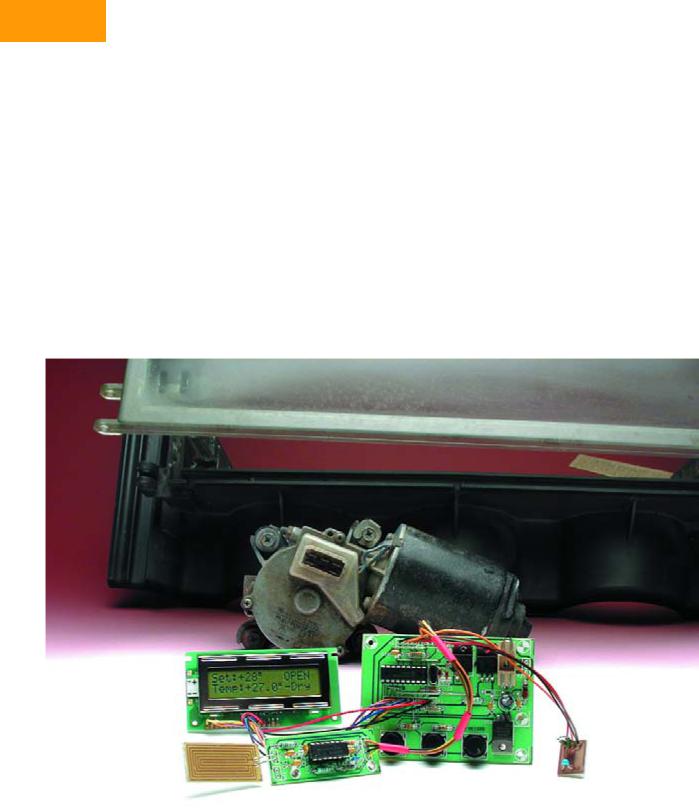
HANDS-ON HOME AUTOMATION
Automatic Attic Window Controller
With a weather dependent control
Raymond Arets
Electronic engineers are often ardent collectors. “Throwing these old parts away would be a waste”, is an often-heard phrase. This results in attics and garages that are overflowing with boxes full of the things, much to the dismay of the other occupants of the house. A fair number of these items can be used in this design, reducing the size of your spare parts mountain.
The design for the attic window controller is based around the well-known PIC16F84. This versatile, and inexpensive, microcontroller has almost become a standard workhorse for pro-
jects like these. The program is written in a language called ‘JAL’, which we’ll cover later on. An old windscreen wiper motor is used to open and close the window.
Description
Figure 1 shows all the electronic modules used in this design. With the help of the circuit diagrams in Figure 1 we’ll explain how the circuit works
56 |
elektor electronics - 1/2006 |

and describe the part played by the different modules.
At the hart of the circuit is IC2, a PIC16F84. This microcontroller uses a rain sensor and a temperature sensor to keep in touch with the outside world. The signals from these sensors affect what the controller shows on the display and what the motor does. The temperature is read every 30 seconds, whereas the rain sensor is monitored continuously.
For the display a standard 2× 16 character LCD is used (also available from Elektor Electronics, order code 03045173; see Figure 5).
T1 and T2 have to deal with the relatively large current of the motor. They may of course be different types than
those specified in the parts list, as long as they can withstand the current (minimum 3 A, and preferably more because of the large peak currents of the motor). The driving voltage (12 V) probably won’t be a problem. RB6 and RB7 on the microcontroller are used to drive the gates. T1 and T2 are connected to the ground side of the motor, since in this configuration there is no need to use a level-shifter.
Figure 2 shows how the windscreen wiper motor is set up. In Figure 3 you can see the mechanical construction made by the author. It isn’t overly difficult, but it helps if you don’t have two left hands.
The function of switches S1 and S2 depends on the mode. During automa-
tic mode the temperature at which the window is opened is increased by S1 and decreased by S2. When manual mode is selected and S1 is pressed the motor will turn on for a certain time, which has been defined in the software. This causes the skylight to open. How far the window opens depends on how long the motor is turned on. When S2 is pressed during manual mode the window will be closed. This is because the motor will stay on until the slider stops making contact with the slip-ring. At that instant the motor is in its original position and the window will therefore be shut. S3 is used to switch between manual and automatic operation.
It is worth mentioning that a little trick
RAIN SENSOR
TEMP. SENSOR
K4
+12V
0
K1
|
|
|
|
|
+5V |
|
|
|
|
|
+12V |
+5V |
|
|
|
|
|
|
|
|
|
|
|
R1 |
|
|
|
C11 |
|
|
|
|
|
|
10k |
|
|
|
|
|
|
|
|
|
|
|
|
|
|
|
|
|
|
|
|
|
|
|
|
|
100n |
|
|
|
|
K5 |
|
|
|
|
14 |
|
|
|
|
|
|
|
4 |
MCLR |
|
RA1 |
18 |
|
|
|
|
|
|
|
|
17 |
|
|
|
|||
|
|
|
|
|
|
RA0 |
|
|
|
|
|
|
|
|
|
|
11 |
|
|
|
|
|
|
|
|
|
IC2 |
RB5 |
|
|
|
|
|
|
1 |
|
|
10 |
|
|
|
||
|
|
RA2 |
|
|
RB4 |
|
|
|
||
|
|
2 |
|
|
9 |
|
|
|
||
|
|
RA3 |
|
|
RB3 |
|
|
|
||
|
|
3 |
|
|
8 |
|
|
|
||
|
|
RA4 |
|
|
RB2 |
|
|
|
||
|
|
|
PIC16F84 |
|
|
|
|
|||
K2 |
|
|
|
RB1 7 |
|
|
|
|||
|
|
|
|
|
|
RB0 |
6 |
|
|
|
SCLK |
|
|
|
|
12 |
|
|
|
||
|
|
|
|
RB6 |
|
|
|
|||
SDA |
|
|
|
|
|
13 |
|
|
|
|
|
|
|
|
|
RB7 |
|
|
|
||
|
|
|
|
|
|
|
|
|
|
|
|
|
|
OSC2 |
OSC1 |
|
|
|
|
|
|
|
|
|
15 |
16 |
5 |
|
|
|
|
|
|
|
|
|
X1 |
|
|
|
|
|
|
+12V |
|
|
|
|
|
|
|
|
|
|
|
|
|
C2 |
|
C1 |
|
|
|
|
|
|
L1 |
27p |
4MHz 27p |
|
|
|
|
|
||
|
|
|
|
|
|
|
|
|
|
|
|
|
|
|
|
|
|
|
D |
T1 |
|
|
22 H |
|
|
|
|
|
G |
|
G |
|
|
IC4 |
|
|
|
|
|
||||
|
|
|
|
|
R5 |
|
R6 |
|
||
|
|
7805 |
|
+5V |
S |
|
||||
|
|
|
100k |
|
100k |
|||||
|
|
|
|
|
|
|
34N |
|||
|
|
|
|
|
|
|
|
IRFZ |
|
|
|
R4 |
|
|
|
|
|
|
|
|
|
C3 |
C4 |
|
|
|
C5 |
|
|
|
|
|
100n |
100 |
|
|
|
100n |
|
|
|
|
|
|
25V |
S14K25 |
|
|
|
|
|
|
|
|
|
TEMP. SENSOR |
|
|
|
|
|
RAIN SENSOR |
|||
R2 |
R3 |
|
|
|
C6 |
|
|
|
|
|
10k |
10k |
|
|
|
|
K8 |
SE1 |
|||
|
8 |
|
|
|
|
|
||||
|
|
|
|
100n |
|
R12 |
|
|
||
|
|
|
|
|
|
|
|
|||
|
|
|
|
|
|
|
|
|
|
|
|
2 |
SCL IC1 |
A0 |
7 |
|
|
100 Ω |
|
|
|
|
1 |
SDA |
|
A1 |
6 |
|
|
5W |
|
|
|
3 |
|
5 |
|
|
|
|
|||
|
OS LM75 |
A2 |
|
|
|
|
|
|||
|
|
|
|
|
|
|
|
|||
|
|
|
4 |
|
|
|
|
|
|
|
R7 10k
+12V
F1
3A K6
+12V
OPEN
CLOSE
D
T2
S1 S2
S
IRFZ
34N UP/ OPEN
R9
18k
|
IC5.A |
1 |
|
3 |
|
||
& |
2 |
||
C9 |
|||
|
|
K9 100n
K10
C10
100n
C7
10n
+5V
R8 |
|
|
LCD1 |
|
10k |
|
K3 |
|
|
P1 |
|
|
||
|
1 |
VSS |
|
|
|
|
2 |
|
|
|
|
VDD |
|
|
|
|
3 |
|
|
|
|
VO |
|
|
CONTR |
10k RB4 |
4 |
|
|
RS |
|
|||
|
|
5 |
|
|
|
|
E |
2x16 |
|
|
RB5 |
6 |
R/W |
|
|
|
|
||
|
|
7 |
D2 |
Display |
|
|
8 |
D0 |
|
|
|
D1 |
|
|
|
|
9 |
|
|
|
|
|
|
|
|
|
10 |
D3 |
LC |
|
RB0 |
11 |
||
|
D4 |
|
||
|
RB1 |
12 |
|
|
|
D5 |
|
||
|
RB2 |
13 |
|
|
|
D6 |
|
||
|
RB3 |
14 |
|
|
|
D7 |
|
||
|
|
|
|
|
D1 |
|
|
|
|
D2 |
|
|
|
|
2x |
|
|
|
|
1N4148 |
|
|
|
|
S3 |
|
|
|
|
DOWN/ |
MANUAL/ |
|
|
|
CLOSE |
AUTO |
|
|
|
|
IC5 = 4093B |
|
|
|
|
||
|
|
|
|
|
|
|
K7 |
|
8 |
IC5.C |
|
|
|
|
|
|
|
10 |
|
|
|
|
|
|
9 |
& |
|
|
|
|
|
|
|
|
|
|
|
||
|
|
|
|
|
D3 |
IC5.B |
|
|
|
1N4148 |
|
|
|
||
11 |
|
|
4 |
|
|||
& |
IC5.D |
|
|
& |
|
||
12 |
13 |
|
R11 |
10k |
5 |
6 |
|
|
|
|
|||||
|
|
|
|
|
|
14 |
C12 |
|
|
|
|
|
|
|
|
|
|
IC5 |
|
R10 |
R13 |
7 |
100n |
|
|||
1M |
C8 |
|
|
1M |
|
|
|
|
100n |
|
|
050139 - 11
Figure 1. The circuit may appear elaborate at first sight, but if you look closer you’ll find that it consists of just a few simple modules. There is even room for an I2C bus.
1/2006 - elektor electronics |
57 |

HANDS-ON HOME AUTOMATION
+12V
M
CLOSE |
OPEN |
(T2) |
(T1) |
|
050139 - 12 |
Figure 2. Connections to the windscreen wiper motor.
was used when S3 was added. There weren’t any more pins available on the PIC16F84 to add a switch for changing between manual and automatic mode. The author used the following trick to get round this: he added S3 in such a way that it appears to the PIC that S1 and S2 are pressed simultaneously. D1 and D2 prevent S1 and S2 from interfering with each other.
An LM75 is used for the temperature sensor. This digital temperature sensor has an I2C interface and can be read at any time. The temperature range runs from -55 to 125 °C, with an accuracy of ±3 degrees. Address lines A0 to A2 can be used to connect up to eight LM75s to one I2C bus, but in this case
Figure 3. Apart from the electrical work, some mechanical construction is also needed.
Figure 4. The rain sensor can be made from the board out of an old keyboard (left), or you can etch your own (right). The corrosion on the author’s sensor was caused by the DC voltage that was applied in the first prototype version.
that is obviously not necessary. More information about I2C can be found previous issues of Elektor Electronics; simply use the Search box on our website to locate the articles).
It is of course possible to use an expensive rain sensor, but it is easier to use a piece of PCB from an old keyboard (see Figure 4). A gold-plated sensor is obviously most resistant to corrosion, but this is difficult to implement if you etch the sensor yourself. To keep the sensor from conducting too long it is heated and dried by R12, which is mounted directly underneath the sensor.
To avoid corrosion as much as possible you have to make sure that there is no DC voltage across the sensor. If this should happen the tracks would quickly corrode due to electrolysis. For this reason an oscillator has been built around IC5a. The exact frequency doesn’t matter here; the only function of the oscillator is to provide an AC voltage to the sensor. In our case the frequency was about 10 kHz, but this is not critical.
The circuit round IC5c and IC5d functions as a buffer. R10 keeps the input of IC5d low when it is dry, but when the sensor becomes wet it starts to conduct and a pulsing signal will appear at the input to IC5d via C10. This pulsing signal charges C8 via IC5c, D3 and R11. D3 stops C8 from discharging via IC5c, leaving R13 as the only discharge path. In this way the signal from the sensor is averaged out. The output of IC5b therefore goes low when rain is detected. This is fed to the PIC, which then closes the attic window.
The power for IC2 and IC5 is regulated by a simple circuit around IC4. L1 acts as a choke and varistor R4 suppresses voltage spikes. R4 isn’t really necessary when a lead-acid battery is used. The construction is fairly straightforward (see Figure 5). No components have been used that are difficult to solder. The soldering of the SMD packaged LM75 may require some more attention (this is mounted on the underside of the temperature sensor board), but it shouldn’t cause any problems. The layout of this board is shown in Figure 6.
Software
As we mentioned earlier, the software was written in JAL (Just Another Language, [1]). JAL is a simple programming language, which even beginners should find easy to follow. Because of this the software can also be adapted easily to your own requirements.
58 |
elektor electronics - 1/2006 |

Figure 5. The construction is fairly straightforward. Remember to solder the wire-links first.
As usual we start by defining the inputs, outputs and variables. For the clock speed we’ve used 4 MHz. When you use the 10 MHz version you should use the 16f84_10 library instead of 16f84_4. At switch-on the temperature setting (address 0), the last position of the window (address 1) and the bit for
COMPONENTS LIST
Resistors:
R1,R2,R3,R7,R8,R11 = 10kΩ
R4 = varistor type S14K25
R5,R6 = 100kΩ
R9 = 18kΩ
R10,R13 = 1MΩ
R12 = 100Ω 5W
P1 = 10kΩ preset
Capacitors:
C1,C2 = 27pF
C3,C5,C6,C8-C12 = 100nF
the operating mode (address 2) are retrieved from the EEPROM. If a temperature is read that is less than 5 or higher than 35 degrees (centigrade), it will be changed into 15 degrees. These minimum and maximum temperatures can be changed in the procedures ‘readbutton_up’ and ‘readbutton_down’.
The procedure ‘readtemp’ read the temperature from the LM75 and displays it on the LC display. A counter is included in this procedure (‘flash’), which is used when the word ‘dry’ has to be flashing on the display. There is a refresh procedure that restricts the measurement of the temperature to about twice a
C4 = 100µF 25V radial
C7 = 10nF
Semiconductors:
D1,D2,D3 = 1N4148 T1,T2 = IRFZ34N IC1 = LM75
IC2 = PIC16F84A-20I/P, programmed, order code 050139-41
IC3 = not fitted IC4 = 7805 IC5 = 4093
Miscellaneous:
L1 = 22µH miniature choke
X1 = 4MHz quartz crystal
F1 = fuse, 3AT (slow) with PCB mount holder
K1,K2,K5,K7 = 4-way SIL connector
K3 = 14-way SIL connector
K4 = 2-way PCB terminal block, lead pitch 5mm
K6 = 3-way PCB terminal block, lead pitch 5mm
K8,K9,K10 = 2-way SIL connector S1,S2,S3 = pushbutton, 1 make contact LCD module, 2x16 characters, e.g. order
code 030451-73 (P-LED) or
030451-72
PCB, ref. 050139-1 from The PCBShop (see www.elektor-electronics.co.uk)
Disk, PIC sourceand hex code, order code 050139-11 or Free Download.
1/2006 - elektor electronics |
59 |

HANDS-ON HOME AUTOMATION
K2 |
|
|
|
3AT |
|
|
|
|
|
|
|
C11 |
R1 |
K5 |
R6 |
F1 |
|
|
|
||||
|
|
|
|||
|
|
X1 |
T2 |
T1 |
|
|
|
|
C1 |
|
|
ELEKTOR |
IC2 |
|
|
|
|
|
|
C2 |
|
|
|
R8 |
|
R5 |
R4 |
C4 |
|
(C) |
|
||||
|
|
|
|
|
|
K3 |
|
|
|
|
|
|
|
R7 |
P1 |
|
|
|
|
|
C5 |
|
|
|
|
|
|
|
|
|
D1 |
|
D2 |
IC4 |
|
050139-1 |
|
050139-1 |
|
||
|
|
|
|
|
|
|
S2 |
S1 |
|
S3 |
|
|
K6 |
R12 |
K10 |
|
|
|
|
|
|
|
open+12Vclose |
K8 |
C10 |
R10 |
|
|
|
C9 |
|
C3 |
|
C12 |
|
|
|
|
|
|
|
|
L1 |
R9 |
IC5 |
|
|
+12V |
R11 |
R13 |
D3 |
|
|
|
||
K4 |
0 |
C7 |
C8 |
|
|
|
|
||
|
|
K7 |
|
|
C6 |
|
|
IC1 |
R3 |
R2 |
|
|
 K1
K1

 K9
K9
050139-1
ELEKTOR (C)
Figure 6. PCB and component layout of the attic window controller.
minute, so that the display of the temperature doesn’t change so often.
The line ‘d = d + 3’ is to correct the temperature reported by the LM75, which in our case was 3 degrees too low. With the help of this line you can therefore calibrate your own sensor, making the temperature shown on the display the real temperature.
The controller can be in one of three states:
• ‘Rain’ indicates that it is raining,
•‘dry’ (flashing) means that it is dry now, but it has rained in the last 20 minutes,
•‘dry’ (constant) means that it has been dry for at least 20 minutes.
The variable ‘dry’ in the software determines the delay after the last detected raindrop. This stops the window being opened in between two showers. It is only when the set
amount of time has passed (‘80’ corresponds to about 20 minutes), that the window is opened again (as long as the temperature isn’t too low, of course).
The procedure ‘keys_both’ checks if the up and down buttons are pressed simultaneously (or S3). If this is the case then the mode will switch between automatic and manual. In the manual mode the window can be opened or closed at any time. The rain sensor is then ignored and the display shows ‘manual’ to reflect the new operating mode.
In the procedures ‘open’ and ‘close’ you can set the length of time required to open and close the window.
And finally...
Because we’ve used a windscreen wiper motor it doesn’t matter if the programmed closing period is too long.
The motor always stops at its end position due to the slip-ring, which in this case means that the skylight is closed. The ‘open’ time can be varied to control how far the window opens. When the attic window controller is set to automatic the skylight will open when it is dry and the temperature is above the set value. The window closes again when the temperature drops more than three degrees below the set temperature or when it starts raining. A lead-acid battery from a car can be used to supply the windscreen wiper motor, but it is also possible to use a PC power supply for this. The current through the motor can rise up to about 3 A, but this shouldn’t be a problem for most PC power supplies.
The rain sensor should naturally be left fully exposed to the outside elements.
(050139-1)
[1] JAL: http://jal.sourceforge.net
60 |
elektor electronics - 1/2006 |