

диафрагмированные волноводные фильтры / 0fd0fe9d-67ae-4cd8-ae37-f248ac6a2708
.pdfCPW-Fed UWB Antenna with Dual Notch-Band Using Embedded Slot Resonator
Guang Yang, Qing-Xin Chu, and Zhi-Hong Tu
School of Electronic and Information Engineering,
South China University of Technology, Guangzhou, Guangdong, China yang.guang@mail.scut.edu.cn, qxchu@scut.edu.cn, and zhtu@scut.edu.cn
Abstract- A CPW-Fed ultra-wideband antenna with dual notch-band using embedded slot resonator is presented in this paper. Stub-loaded open-loop resonator can be utilized to design compact dual-band bandpass filters with improved out-of-band rejection characteristic. When the stub-loaded open-loop resonator embedded into the feed line of the UWB antenna and transformed into slot resonator, dual notched band property is obtained. By adjusting the parameters of the embedded slot resonator, the dual band-notched UWB antenna can be adopted to minimize the potential interference between the UWB system and the narrow band systems, such as systems in the WiMAX/WLAN bands.
I.INTRODUCTION
The ultra-wideband (UWB) technology has become one of the most promising technologies for short-range high-rate indoor wireless communications, since the Federal Communications Commission (FCC) assigned the frequency band of 3.1-10.6 GHz for its commercial application in 2002 [1]. But the UWB frequency range will cause interference with the existing narrow band wireless communication systems, such as WiMAX and WLAN covering the 3.3–3.6 GHz and 5.15–5.825 GHz.
As the key components of UWB systems, it is desired UWB antennas have band-notches at these existing narrow frequency bands. Many planar monopole UWB antennas with multi-band notched characteristics have been reported [2-8]. To some microstrip-fed UWB antennas, band-notched characteristics were implemented by adding stepped impedance resonators (SIRs) or split ring resonators (SRRs) on the feed lines [2]. To others UWB antennas, especially for CPW-fed antennas, bandrejected characteristics were obtained by cutting various slots on radiating patches or/and ground plane, such as C-Shaped slots [3-4], E-shaped slots [5], U-shaped slots [6-7], and arc shaped slots [8]. But input impedance bandwidths (above - 10dB return loss) of these notches are too wider than WiMAX and WLAN frequency ranges, which may result in the degradation of some UWB signals close to them. At the same time, there was no sufficient discussion on how to implement dual band-notched characteristics on the feed line for CPW-fed UWB antennas.
In this paper, a compact CPW-fed UWB antenna with dual narrow band-notches is proposed. Two stub-loaded open-loop slot resonators are embedded into the feed line to obtain dual band notches at both WiMAX and WLAN frequency. A model of stub-loaded open-loop resonator is introduced to explain
how the two slot resonators generate the notched bands [9]. In order to have good impedance matching, the slot resonators are designed with different shapes and different feeding positions. Details of the proposed antenna, simulated and measured results are presented and discussed.
II.ANTENNA DESIGN AND DISCUSSION
(a)
(b)
Figure 1 (a) Geometry of the proposed antenna,(b) Geometry of slot resonators
Figure 1(a) shows the geometry and configuration of the proposed dual band-notched antenna. It is printed on a low-cost FR4 substrate with the thickness of 0.8mm and the dielectric constant of 4.4. The size of the antenna is 30mm 30mm, and a 50Ohm CPW-fed structure is employed. The radiator is a part of a circular patch of R=18mm, and the ground plane is modified to obtain better impedance matching. Two stubloaded open-loop slot resonators are embedded into the feed line to obtain dual band notches to generate dual band notches with centre frequencies of 3.5GHz and 5.5GHz respectively. Figure 1(b) illustrates the structure of embedded slot resonator
978-1-4673-2185-3/12/$31.00 ©2012 IEEE

in detail.
As depicted in Figure 2, the embedded slots on the feed line can be treated as stub-loaded open-loop slot resonators. A shunt open stub is introduced to a conventional open-loop resonator.
Figure 2. Stub-loaded open-loop resonator
If YR and Ys are the characteristic admittances of the resonator and the stub, respectively, then the input admittance of the resonator from the open end (shown by 1 )is
Yin jY |
|
tan 1 tan 2 tan s |
|
|
tan 1(tan 2 tan s ) (1) |
||
1 |
|||
where YR YS Y is assumed for simplicity.
The resonance condition can be obtained from the
following: |
(2) |
|
Yin 0 |
|
|
From (1) and (2), the resonance condition is obtained as |
||
tan(n 1 ) tan(n 2 ) tan(n S ) 0 (3) |
|
|
where n is the ratio of |
resonance frequency fr |
to the |
fundamental resonance f1 . For a preset stub length S |
and its |
|
position 1 , required 2 for the fundamental resonance can be
obtained from (3) by putting n 1.
From the resonance condition (3), the stub-loaded open-loop resonator can be deduced and implemented, as shown in Figure 3(a). The simulated S11/S12 of the stub-loaded open-loop resonator are depicted in Figure 3(b). The S-parameters show that the stub-loaded open-loop resonator filter resonates at the frequencies of 3.5/5.5 GHz, which cause input impedance mismatching at these resonant frequencies. Consequently, the signals in the vicinity of two frequencies are reflected, and thus the filter with dual band-stop characteristic is achieved.
(a)
(b)
Figure 3.(a) Geometry of the stub-loaded open-loop resonator, (b) Simulated S11 and S12 of the resonator
A parametric study of the proposed antenna has been conducted by using the Ansoft’s High Frequency Structure Simulation (HFSS) to explore how the dimensions and placements of the slots affect the characteristic of the notched bands. The optimized parameters are as follows in Table 1.
TABLE 1. The geometry parameters of the proposed antenna(Unit:mm)
R |
H |
L |
W |
Wf |
L_gx |
L_gy |
h |
L_tx |
L_ty |
|
|
|
|
|
|
|
|
|
|
18 |
30 |
30 |
0.4 |
5 |
11.2 |
11.9 |
0.8 |
2.6 |
4.1 |
|
|
|
|
|
|
|
|
|
|
s1 |
s2 |
L1 |
L2 |
L3 |
L4 |
L5 |
L6 |
L7 |
|
|
|
|
|
|
|
|
|
|
|
2.6 |
0.7 |
9.3 |
1.4 |
12 |
1 |
3.8 |
1.2 |
6.8 |
|
|
|
|
|
|
|
|
|
|
|
Figure 4. Simulated VSWR of varied L1
Figure 5. Simulated VSWR of varied L2
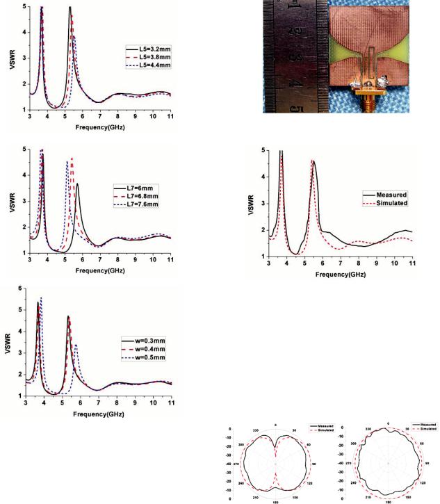
Figure 6. Simulated VSWR of varied L5
Figure 7. Simulated VSWR of varied L7
Figure 8. Simulated VSWR of varied slot widths
The variation of simulated VSWR with different slot lengths is shown in Figure 4, 5, 6, and 7 respectively. It can be seen that the VSWR curves have similarly graphical trend for the three different lengths, and at the same time the centre frequencies of the dual notched band will get smaller with longer slots.
The variation of simulated VSWR with different slot widths is shown in Figure 8. It is shown that the wider slot width brings out higher centre frequencies of the dual notched band. The dual notched band changes significantly with the variation of the slot width.
III. RESULTS
Figure 9. Photograph of proposed antenna (Unit: mm)
The proposed antenna is fabricated, as shown in Figure 9, based on the design parameters listed in Table 1.
Figure 10. Simulated and measured VSWR
The measurement is taken by Agilent R3770 vector network analyzer and the antennas measurement system of South China University of Technology. The simulated and measured VSWR of the proposed antenna are well in agreement as shown in Figure 10. The measured bandwidth for VSWR<2 has small disagreement with the simulations, which covers the frequency range of 3.1~10.6GHz except in 3.3~3.6GHz and 5.1~5.9GHz. In the desired notched dual band, 3.3~3.6GHz for WiMAX and 5.15~5.825GHz for WLAN, the values of VSWR are all nearly bigger than 2. Therefore, the potential interference between UWB systems and the two narrow bands systems obtains good suppression perfectly.
(a) |
(b) |

(c) |
(d) |
(e) |
(f) |
Figure 11. Measured and simulated radiation patterns. (a) E-plane(xy) at 4GHz.
(b) H-plane (yz) at 4GHz. (c) E-plane (xy) at 7GHz. (d) H-plane (yz) at 7GHz.
(e) E-plane (xy) at 10GHz. (f) H-plane(yz) at 10GHz.
Figure 12. Measured Gain of the proposed antenna
The simulated and measured radiation patterns of the proposed antenna in the E-plane (xy-plane) and H-plane (yzplane) for three different frequencies 4GHz, 7GHz and 10GHz are shown in Figure 11. The radiation patterns between the simulation and measurement match well except in some orientations. The patterns in the H-plane are quite omnidirectional as expected to receive signals from all directions. The measured gain of the proposed antenna is shown Figure 12. As desired, gain decreases sharply in the vicinity of 3.5GHz and 5.5GHz, which demonstrates the good band-rejection function of the proposed antenna.
IV. CONCLUSION
In this paper, a compact CPW-fed UWB antenna with dual narrow band-notches has been proposed, implemented and discussed. Two stub-loaded open-loop slot resonators have been embedded into the feed line to obtain dual band notches at both WiMAX and WLAN frequency. The proposed antenna has good impedance match and stable gain in the entire UWB band except in the two notched bands. The values of VSWR are all nearly bigger than 2 in the desired dual bands for
WiMAX and WLAN. The normalized radiation patterns are nearly omni-directional over the whole operation frequencies.
ACKNOWLEDGMENT
This work was supported by the National Natural Science Foundation of China (61171029)
REFERENCES
[1]Federal Communications Commission Revision of Part 15 of the Commission’s Rules Regarding Ultra-Wideband Transmission System From 3.1 to 10.6 GHz. Washington, DC: Federal Communications Commission, 2002, pp. 98–153.
[2]Zhang, Y., W. Hong, C. Yu, Z. Q. Kuai, Y. D. Don, and J. Y. Zhou, “Planar ultrawideband antennas with multiple notched bands based on etched slots on the patch and/or split ring resonators on the feed line," IEEE Trans. Antennas and Propagations, vol. 56, no. 9, pp.3063-3068, Sep. 2008.
[3]Chu, Q.X., and Yang, Y.Y., “A compact ultra wideband antenna with 3.4/5.5GHz dual band-notched characteristics,” IEEE Trans. Antennas Propag., vol.56, no.12, pp.3637-3644, Dec. 2008.
[4]Zheng, Z.A., and Chu, Q.X., “Compact CPW-fed UWB antenna with dual band-notched characteristics,” Progress In Electromagnetics Research Lett., vol.11, pp.83-91, 2009.
[5]Luo, L., Cui, Z., Xiong, J.P., Zhang, X.M., and Jiao, Y.C, “Compact printed ultra-wideband monopole antenna with dual band-notch
characteristic,” Electron. Lett., vol.44, no.19, pp. 1106 1107, Sept. 2008,
[6]Yin, K., and Xu, J.P., “Compact ultra-wideband antenna with dual
bandstop characteristic,” Electron. Lett., 2008, vol.44, no.7, pp.453 454, Apr. 2008.
[7]Y.S. Li, X.D. Yang, C.Y. Liu and T. Jiang, “Compact CPW-fed ultrawideband antenna with dual band-notched characteristics,” Electron. Lett., vol.46, No.14, pp.967-968, Jul. 2010.
[8]N.D. Trang, D.H. Lee and H.C. Park, “Compact printed CPW-fed monopole ultra-wideband antenna with triple subband notched characteristics,” Electron. Lett., vol.46, no.17, pp.18-19, Aug. 2010.
[9]P. Mondal, , M. K. Mandal, “Design of dual-band bandpass filters using stub-loaded open-loop resonators,” IEEE Transactions on Microwave Theory and Techniques, vol. 56, NO. 1, pp. 150155, Jan. 2008