

диафрагмированные волноводные фильтры / 2a4347b3-f170-4ec5-be26-a2a242f534dc
.pdfDual-polarized operations are required in many multiple-antenna wireless communication systems.
stable radiation patterns across the entire tuning range. The configuration and S-parameters of the DRA are presented in Figures 14 and 15. The fundamental TE111 mode of the DRA is excited by the differential feeding scheme of a slot etched on the ground plane and a 50-Ω microstrip feed line with differential ports 1 and 2 at
|
Port 1(a) and (b) |
Port 2(a) and (b) |
|
|
|
|
|
|
|
|
(0 and 180°) |
|
|
|
|
|
|
||
|
|
(0 and 180°) |
|
|
|
|
|
|
|
|
|
Substrate |
Ground Plane |
|
|
||||
|
|
|
|
|
|
|
|
||
|
|
|
(a) |
|
|
|
|
|
|
|
|
|
Probe 2(a) |
Port 1 |
|
|
|||
|
Feeding Network |
(Port 2: 0°) |
|
|
|
|
|
|
|
|
|
|
|
Feeding |
|
|
|||
|
Port 2 |
|
Network |
|
|
||||
|
|
|
|
|
|
|
|
||
|
|
|
|
Probe 1(a) |
|||||
|
|
Probe 1(b) |
(Port 1: 0°) |
||||||
|
|
|
|
|
|
|
|
||
|
|
(Port 1: 180°) |
|
|
|
|
|
|
|
|
|
|
|
Hook Shape |
|
|
|||
|
|
|
Probe 2(b) |
|
|
|
|
|
|
|
|
|
(Port 2: 180°) |
|
|
|
|
|
|
|
|
|
(b) |
|
|
|
|
|
|
|
0 |
|
|
|
|
|
|
|
|
(dB) |
–10 |
|
|
|
|
|
|
|
|
–20 |
|
|
|
|
|
|
|
|
|
Parameters |
|
|
|
|
|
|
|
|
|
–40 |
|
|
|
|
|
S11 |
|
|
|
|
–30 |
|
|
|
|
|
|
|
|
S- |
–50 |
|
|
|
|
|
S12 |
|
|
|
|
|
|
|
|
|
|||
|
|
|
|
|
|
|
S22 |
|
|
|
–60 8 |
|
|
|
|
|
|
|
|
|
9 |
10 |
11 |
|
|
|
12 |
||
|
|
Frequency (GHz) |
|
|
|||||
(c)
Figure 16. The dual-polarized, hook-shaped, probe-excited DRA [28]. The (a) 3D view, (b) top view with feeding networks, and (c) simulated S-parameters.
34
each end. The resonance frequency of the TE111 mode decreases as the capacitance increases or the bias voltage of the varactors decreases, forming a frequencytunable differentially fed DRA.
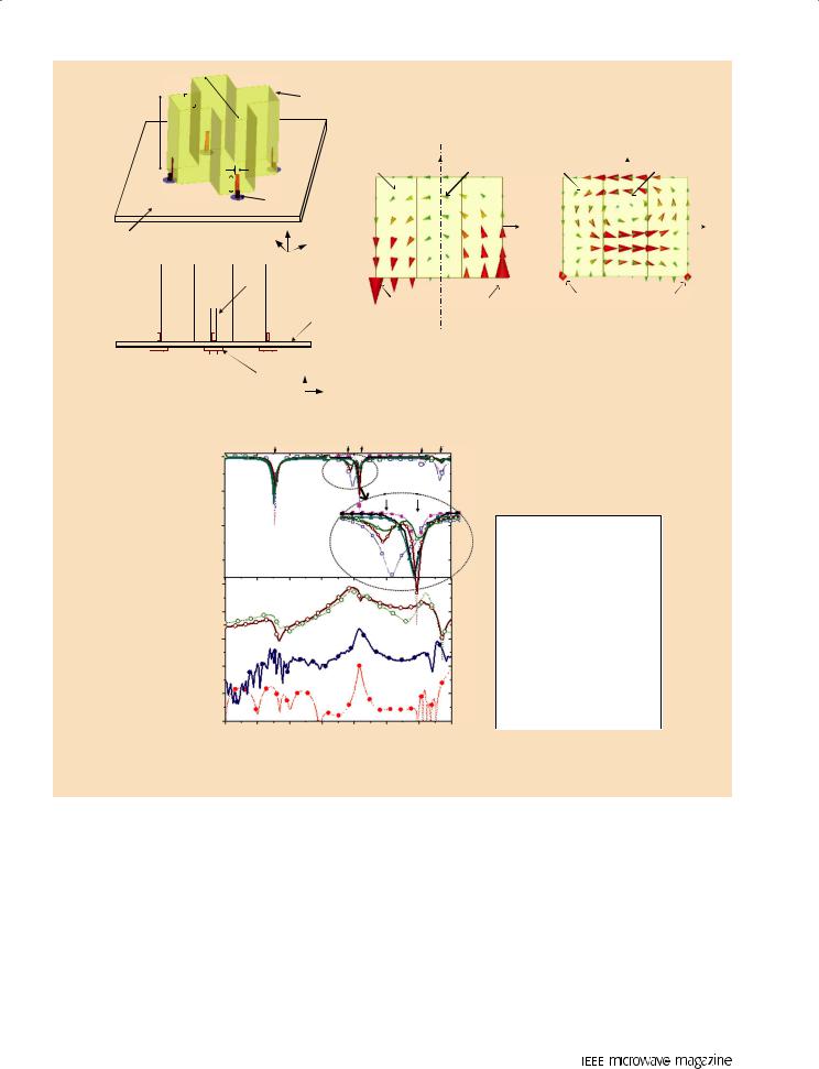
In addition to various other antenna applications, dual-polarized operations are required in many multiple-antenna wireless communication systems, including those for diversity implementation and multiple-input, multiple-output systems. Dual-polarized DRAs are also being introduced as possible replacements for metallic antennas. A dual-polarized antenna generates two polarizations on a single antenna element and maintains reasonable isolation between ports. In addition to the aforementioned merits, exciting a dual-polarized DRA by a pair of balanced signals is one effective solution to improve isolation. Differential cylindrical [28] DRAs excited by hookor J-shaped probes [pictured in Figure 11(d)] are designed for dual-polarization applications with high-level port isolations. The configurations of the DRAs and the simulated S-parameters appear in Figure 16(a)–(c), indicating isolation greater than 45 dB.
The authors of [40] proposed a differential dualband, dual-polarized DRA using a cross-shaped DR with the configuration shown in Figure 17(a). The principle behind its high isolation is investigated in [40] and revealed to be derived from the fact that one differential excitation forms a virtual ground plane that has no effect on the corresponding modes while suppressing the orthogonal modes, as illustrated in Figure 17(b). The S-parameters of the differential dual-band, dual-polarized DRA are depicted in Figure 17(c), which also indicates the elimination of in-phase higher-order modes, a benefit of the differential feed scheme.
Conclusions
DRs are widely used in modern wireless communication systems due to their advantages of low loss, high power capacity, and excellent temperature stability. Compared with traditional single-ended excitation, the differential feeding method can achieve excellent performance, such as high immunity to interference, greater reliability, significant output power, and superior harmonic suppression. This article investigated differentially fed DR approaches based on the characteristics of DR and differential circuit technologies and summarized several typical applications in filter and antenna designs, showing excellent performance, such as reduced insertion loss, higher passband selectivity in filters or broader bandwidths, symmetric and stable radiation patterns, and low cross-polarization in antennas.
July 2020
Authorized licensed use limited to: Auckland University of Technology. Downloaded on June 02,2020 at 08:49:58 UTC from IEEE Xplore. Restrictions apply.
3D View |
l |
|
|
|
|
|
|
|
DR |
|
|
|
|
|
|
||||||||
|
|
|
|
|
|
|
|
|
|
|
|
|
|
|
|
|
|
|
|||||
|
b |
Port 2′ |
|
|
|
|
|
|
|
|
|
TE1δ1 Mode |
TE1δ3 Mode |
||||||||||
|
|
|
|
|
|
|
|
|
|
|
|
|
|
|
|||||||||
|
|
|
|
|
|
|
|
|
|
ws |
|
|
|
Port 1′ |
Rectangular |
z |
Rectangular |
Rectangular |
|
Rectangular |
|||
|
|
|
|
|
|
|
|
|
|
|
|
|
DR A |
DR B |
DR A |
z |
DR B |
||||||
|
|
|
|
|
|
|
|
|
|
|
|
|
|
|
|
|
|
||||||
Port 1 |
|
|
|
ls |
Coaxial |
|
|
|
|
|
|
|
|||||||||||
|
|
|
|
|
|
|
|
|
|
|
|
|
|
|
|
|
|
|
|||||
|
|
|
|
|
|
|
|
Port 2 |
Aperture |
|
|
|
x |
|
|
x |
|||||||
|
|
|
|
|
|
|
|
|
|
|
|
|
|
|
|
z |
|
|
|
|
|
||
Ground Plane |
|
|
|
|
|
|
|
|
|
|
|
|
|
|
|
|
|
|
|||||
|
|
|
|
|
|
|
|
y |
x |
|
|
|
|
|
|
||||||||
|
|
|
|
|
|
|
|
|
|
|
|
|
|
|
|
|
|
|
|||||
|
|
|
|
|
|
|
|
|
|
|
|
|
|
|
|
|
|
|
|
|
|
|
|
Side View |
|
|
|
Metallic |
Strip |
|
|
|
|
|
|
|
|
|
|
||||||||
|
|
|
|
|
|
|
|
|
|
|
|
|
|
|
|
||||||||
|
|
|
|
|
|
|
|
|
|
|
|
|
|
|
|
Ground |
Differential |
|
Differential |
Differential |
|
Differential |
|
|
|
|
|
|
|
|
|
|
|
|
|
|
|
|
|
Plane |
Feeding (+) |
|
Feeding (–) |
Feeding (+) |
|
Feeding (–) |
|
|
|
|
|
|
|
|
|
|
|
|
|
|
|
|
|
|
|
Virtual Ground |
Virtual Ground |
||||
|
|
|
|
|
|
|
|
|
|
|
|
|
|
|
|
|
|
||||||
|
|
|
|
|
|
|
|
|
|
|
|
|
|
|
|
|
|
||||||
|
|
|
|
|
|
|
|
|
|
|
|
|
|
|
|
|
|
|
|
|
|
|
|
Port 1 |
Port 2 |
|
|
|
|
Port 1′ |
z |
|
|
|
|
|
|
||||||||||
|
|
|
|
|
|
(2′) |
|
SMA |
|
|
|
|
|
|
|||||||||
|
|
|
|
|
|
|
x |
|
|
|
|
|
|
||||||||||
|
|
|
|
|
|
|
|
|
|
Connector |
|
|
|
|
|
|
|||||||
|
|
|
|
|
|
|
|
|
|
|
|
|
|
|
|
|
|||||||
|
|
|
|
|
|
|
|
|
|
|
(a) |
|
|
|
|
(b) |
|
|
|||||
(dB) |
0 |
|
Coefficient |
–20 |
|
|
||
Reflection |
–40 |
|
–60 |
||
|
||
|
0 |
|
(dB) |
–20 |
|
–40 |
||
Isolation |
||
–60 |
||
|
–80
–100
f1 |
f4 f2 |
f5 f3 |
f4 f2
1 |
1.25 |
1.5 |
1.75 |
2 |
2.25 |
2.5 |
2.75 |
Frequency (GHz)
(c)
 Simulated S11dd and S22dd
 Simulated S21dd
 Simulated S11 and S22
 Simulated S21
 Measured S11dd
 Measured S22dd
 Measured S21dd
 Measured S11
 Measured S22
 Measured S21
Figure 17. The differentially fed, dual-band, dual-polarized DRA using a cross-shaped DR [40]. The (a) configuration, (b) virtual ground formed by differential excitation, and (c) S-parameters.
References
[1]W. R. Eisenstant, B. Stengel, and B. M. Thompson, Microwave Differential Circuit Design Using Mixed-Mode S-Parameters. Boston, MA: Artech House, 2006.
[2]X.-H. Wang, H. Zhang, and B.-Z. Wang, “A novel ultra-wideband differential filter based on microstrip line structures,” IEEE Microw. Compon. Lett., vol. 23, no. 3, pp. 128–130, Mar. 2013. doi: 10.1109/LMWC.2013.2243719.
[3]W. J. Feng, W. Q. Che, and Q. Xue, “The proper balance: Overview of microstrip wideband balance circuits with wideband common mode suppression,” IEEE Microw. Mag., vol. 16, no. 5, pp. 55–68, June 2015. doi: 10.1109/MMM.2015.2408275.
[4]B. Xia, L.-S. Wu, S.-W. Ren, and J.-F. Mao, “A balanced-to-balanced power divider with arbitrary power division,” IEEE Trans. Microw. Theory Techn., vol. 61, no. 8, pp. 2831–2840, Aug. 2013. doi: 10.1109/ TMTT.2013.2268739.
[5]S. Liao, P. Wu, K. M. Shum, and Q. Xue, “Differentially fed planar aperture antenna with high gain and wide bandwidth for millime- ter-wave application,” IEEE Trans. Antennas Propag., vol. 63, no. 3, pp. 966–977, Mar. 2015. doi: 10.1109/TAP.2015.2389256.
[6]Q. Xue, S. W. Liao, and J.-H. Xu, “A differentially-driven dualpolarized magneto-electric dipole antenna,” IEEE Trans. Antennas Propag., vol. 61, no. 1, pp. 425–430, Jan. 2013. doi: 10.1109/ TAP.2012.2214998.
July 2020 |
35 |
Authorized licensed use limited to: Auckland University of Technology. Downloaded on June 02,2020 at 08:49:58 UTC from IEEE Xplore. Restrictions apply.

[7]Ó. Garcia-Perez, D. Segovia-Vargas, L. E. Garcia-Munoz, J. L. Jimenez-Martin, and V. Gonzalez-Posadas, “Broadband differential low-noise amplifier for active differential arrays,” IEEE Trans. Microw. Theory Techn., vol. 59, no. 1, pp. 108–115, Jan. 2011. doi: 10.1109/TMTT.2010.2091199.
[8]D. Kajfez and P. Guillon, Dielectric Resonators. Norwood, MA: Artech House, 1986.
[9]S. B. Cohn, “Microwave bandpass filters containing high-Q dielectric resonators,” IEEE Trans. Microwave Theory Techn., vol. 16, no. 4, pp. 218–227, Apr. 1968. doi: 10.1109/TMTT.1968.1126654.
[10]C. Wang and K. A. Zaki, “Dielectric resonators and filters,” IEEE Microw. Mag., vol. 8, no. 5, pp. 115–127, Oct. 2007. doi: 10.1109/ MMM.2007.903648.
[11]S.-W. Wong, Z.-C. Zhang, S.-F. Feng, F.-C. Chen, L. Zhu, and Q.- X. Chu, “Triple-mode dielectric resonator diplexer for base-station applications,” IEEE Trans. Microw. Theory Techn., vol. 63, no. 12, pp. 3947–3953, Dec. 2015. doi: 10.1109/TMTT.2015.2488658.
[12]Z.-C. Zhang et al., “Triple-mode dielectric-loaded cylindrical cavity diplexer using novel packaging technique for LTE base-station applications,” IEEE Trans. Compon. Packag. Manuf. Technol., vol. 6, no. 3, pp. 383–389, Mar. 2016. doi: 10.1109/TCPMT.2016.2516820.
[13]S. W. Chen and K. A. Zaki, “A novel coupled method for dualmode dielectric resonators and waveguide filters,” IEEE Trans. Microw. Theory Techn., vol. 38, no. 12, pp. 1885–1893, Dec. 1990. doi: 10.1109/22.64570.
[14]M. M. Driscoll et al., “Cooled, ultrahigh Q, sapphire dielectric resonators for low-noise, microwave signal generation,” IEEE Trans. Ultrason., Ferroelect., Freq. Control, vol. 39, no. 3, pp. 405–411, May. 1992. doi: 10.1109/58.143174.
[15]C. Wang, H. W. Yao, K. A. Zaki, and R. R. Mansour, “Mixed modes cylindrical planar dielectric resonator filters with rectangular enclosure,” IEEE Trans. Microw. Theory Techn., vol. 43, no. 12, pp. 2817–2823, Dec. 1995. doi: 10.1109/22.475640.
[16]M. T. K. Tam and R. D. Murch, “Half volume dielectric resonator antenna designs,” Electron. Lett., vol. 33, no. 23, pp. 1914–1916, Nov. 1997. doi: 10.1049/el:19971334.
[17]C. Wang, K. A. Zaki, A. E. Atia, and T. G. Dolan, “Dielectric combline resonators and filters,” IEEE Trans. Microw. Theory Techn., vol. 46, no. 12, pp. 2501–2506, Dec. 1998. doi: 10.1109/22.739240.
[18]K. Wakino, T. Nishikawa, and Y. Ishikawa, “Miniaturization technologies of dielectric resonator filters for mobile communications,” IEEE Trans. Microw. Theory Techn., vol. 42, no. 7, pp. 1295–1300, July 1994. doi: 10.1109/22.299721.
[19]D. Baillargeat, S. Verdeyme, and P. Guillon, “Slotted dielectric resonators for rigorous design of a four-poles dual mode filter,” IEEE Microw. Guided Wave Lett., vol. 4, no. 10, pp. 332–334, Oct. 1994. doi: 10.1109/75.324707.
[20]J. Li, Y. Zhan, W. Qin, Y. L. Wu, and J.-X. Chen, “Differential dielectric resonator filters,” IEEE Trans. Compon. Packag. Manuf. Technol., vol. 7, no. 4, pp. 637–645, Apr. 2017. doi: 10.1109/TCPMT.2017.2669331.
[21]T. D. Iveland, “Dielectric resonator filters for application in microwave integrated circuits,” IEEE Trans. Microw. Theory Techn., vol. 19, no. 7, pp. 643–652, July 1971. doi: 10.1109/TMTT.1971.1127594.
[22]W. Feng and W. Che, “Novel wideband differential bandpass filters based on T-shaped structure,” IEEE Trans. Microw. Theory Techn., vol. 60, no. 6, pp. 1560–1568, June 2012. doi: 10.1109/ TMTT.2012.2188538.
[23]J. Shi and Q. Xue, “Novel balanced dual-band bandpass filter using coupled stepped-impedance resonators,” IEEE Microw. Wireless Compon. Lett., vol. 20, no. 1, pp. 19–21, Jan. 2010.
[24]J.-X. Chen, C. Shao, Q.-Y. Lu, H. Tang, and Z.-H. Bao, “Compact LTCC balanced bandpass filter using distributed-element resonator,” Electron. Lett., vol. 49, no. 5, pp. 354–356, Feb. 2013. doi: 10.1049/el.2012.4071.
[25]H.-C. Chen, C.-H. Tsai, and T.-L. Wu, “A compact and embedded balanced bandpass filter with wideband common-mode suppression on wireless SiP,” IEEE Trans. Compon. Packag. Manuf. Technol., vol. 2, no. 6, pp. 1030–1038, June 2012. doi: 10.1109/TCPMT.2012.2186451.
36
[26]P. Chu, W. Hong, K.-L. Zheng, W.-W. Yang, F. Xu, and K. Wu, “Balanced hybrid SIW-CPW bandpass filter,” Electron. Lett., vol. 53, no. 25, pp. 1633–1655, Dec. 2017.
[27]X. Xu, J. P. Wang, and L. Zhu, “A new approach to design differential mode bandpass filters on SIW structure,” IEEE Microw. Wireless Compon. Lett., vol. 23, no. 12, pp. 635–637, Dec. 2013. doi: 10.1109/ LMWC.2013.2283859.
[28]R. Chair, A. A. Kishk, and K. F. Lee, “Hookand 3-D J-shaped probe excited dielectric resonator antenna for dual polarization applications,” IEE Proc. Microw. Antennas Propag., vol. 153, no. 3, pp. 277–281, June 2006. doi: 10.1049/ip-map:20050134.
[29]B. Li and K. W. Leung, “On the differentially fed rectangular dielectric resonator antenna,” IEEE Trans. Antennas Propag., vol. 56, no. 2, pp. 353–359, Feb. 2008. doi: 10.1109/TAP.2007.915463.
[30]X. S. Fang, K. W. Leung, E. H. Lim, and R. S. Chen, “Compact differential rectangular dielectric resonator antenna,” IEEE Antennas Wireless Propag. Lett., vol. 9, pp. 662–665, 2010. doi: 10.1109/ LAWP.2010.2057402.
[31]R. D. Gupta and M. S. Parihar, “Differentially fed wideband rectangular DRA with high gain using short horn,” IEEE Antennas Wireless Propag. Lett., vol. 16, pp. 1804–1807, 2017.
[32]Y. X. Sun, K. W. Leung, and J. F. Mao, “Dualfunction dielectric resonator as antenna and phase-delay-line load: Designs of compact circularly polarized/differential antennas,” IEEE Trans. Antennas Propag., vol. 66, no. 1, pp. 414–419, Jan, 2018. doi: 10.1109/TAP.2017.2767819.
[33]S. J. Guo, L. S. Wu, K. W. Leung, and J. F. Mao, “Microstrip-fed differential dielectric resonator antenna and array,” IEEE Antennas Wireless Propag. Lett., vol. 17, no. 9, pp. 1736–1739, Sept. 2018. doi: 10.1109/LAWP.2018.2864972.
[34]M. W. Pospieszalski, “Cylindrical dielectric resonators and their applications in TEM line microwave circuits,” IEEE Trans. Microw. Theory Techn., vol. 27, no. 3, pp. 233–238, Mar. 1979. doi: 10.1109/ TMTT.1979.1129599.
[35]E. H. Lim and K. W. Leung, “Use of the dielectric resonator antenna as a filter element,” IEEE Trans. Antennas Propag., vol. 56, no. 1, pp. 5–10, Jan. 2008. doi: 10.1109/TAP.2007.913152.
[36]K.-M. Luk, and K.-W. Leung, Dielectric Resonator Antennas. London, U. K.: Research Studies Press, 2003.
[37]T. Nishikawa, K. Wakino, K. Tsunoda, and Y. Ishikawa, “Dielec-
tric high-power bandpass filter using quarter-cut TE01d image resonator for cellular base stations,” IEEE Trans. Microw. Theory Techn., vol. 35, no. 12, pp. 1150–1155, Dec. 1987. vol doi: 10.1109/ TMTT.1987.1133830.
[38]J.-F. Liang and W. D. Blair, “High-Q TE01 mode DR filters for PCS wireless base stations,” IEEE Trans. Microw. Theory Techn., vol. 46, no. 12, pp. 2493–2500, Dec. 1998. doi: 10.1109/22.739239.
[39]Y. Zhan, J.-X. Chen, W. Qin, and J. Li, “Spurious-free differential bandpass filter using hybrid dielectric and coaxial resonators,”
IEEE Microw. Wireless Compon. Lett., vol. 26, no. 8, pp. 574–576, July 2016. doi: 10.1109/LMWC.2016.2585541.
[40]J.-X. Chen, J. Li, W. Qin, J. Shi, and Z.-H. Bao, “Design of balanced and balun filters using dual-mode cross-shaped dielectric resonators,” IEEE Trans. Microw. Theory Techn., vol. 65, no. 4, pp. 1226–1234, Apr. 2017. doi: 10.1109/TMTT.2016.2635653.
[41]H. Tang, J.-X. Chen, W.-W. Yang, L.-H. Zhou, and W. Li, “Differential dual-band dual-polarized dielectric resonator antenna,” IEEE Trans. Antennas Propag., vol. 65, no. 2, pp. 855–860, Feb, 2017. doi: 10.1109/TAP.2016.2630661.
[42]E. Lee and M. L. C. Ong, “Aperture coupled, differentially fed DRAs,” in Proc. Asia-Pacific Microwave Conf., 2009, pp. 2781–2784. doi: 10.1109/APMC.2009.5385370.
[43]C. X. Hao, B. Li, K. W. Leung, and X. Q. Sheng, “Frequency-tun- able differentially fed rectangular dielectric resonator antennas,”
IEEE Antennas Wireless Propag. Lett., vol. 10, pp. 884–887, 2011. doi: 10.1109/LAWP.2011.2165929.
[44]K. W. Leung, E. H. Lim, and X. S. Fang, “Dielectric resonator antennas: From the basic to the aesthetic,” Proc. IEEE, vol. 100, no. 7, pp. 2181–2193, July 2012. doi: 10.1109/JPROC.2012.2187872.
July 2020
Authorized licensed use limited to: Auckland University of Technology. Downloaded on June 02,2020 at 08:49:58 UTC from IEEE Xplore. Restrictions apply.