

диафрагмированные волноводные фильтры / 2af28f65-68c2-41cc-abee-a23ee69760a6
.pdfA Wideband Diplexer for Ka-Band Passive Intermodulation Measurement
D. Smacchia#1, C. Carceller*, M. Guglielmi*, P. Soto*2, V.E. Boria*3, J. Ruiz*, P. González*
#ESA-VSC High Power RF Laboratory, Valencia E-46022, Spain
*iTEAM - Dpto. de Comunicaciones, Universitat Politècnica de València, Valencia E-46022, Spain
1davide.smacchia@val-space.com, 2pabsopac@dcom.upv.es, 3vboria@dcom.upv.es
Abstract—In this paper we propose a novel Ka-band waveguide diplexer for passive intermodulation (PIM) measurements. Due to the higher operating frequency, this type of measurement setup usually requires wide band filters. In addition, due to the very large separation between satellite uplink and downlink bands, the PIM measurement diplexer unit must operate over a very wide frequency band. To satisfy such wide bandwidth requirements, the proposed topology is based on a band-reject filter for the downlink frequency band which is designed to provide, at the same time, the optimal passband performance for the downlink, and the optimal equiripple rejection over the PIM band. For the PIM channel, a band-pass filter combined with a high-pass section has been used. To validate the design, a prototype has been designed and manufactured. Very good agreement is shown between simulations and measurements, thereby fully validating the proposed solution.
Index Terms—Microwave filters, multiplexing, Ka-band, highpower filters, computer-aided engineering.
I. INTRODUCTION
The continuous demands for higher throughput in modern communication systems is pushing telecoms satellites to higher operating frequencies. Since the launch of the Thaicom- 4 (IPSTAR) satellite in 2005, satellite operators have devoted continuous significant efforts to the development of higher bandwidth systems. In this context, the recently developed High Throughput Satellites (HTS) are exploiting the Ka-band frequency range [1]. The ITU (International Telecommunication Union) has, in fact, assigned a wide bandwidth for satellite applications at Ka-band, ranging from 17.3 GHz to 21.2 GHz for downlink and 27 GHz to 31 GHz for uplink, with a potential future use of the 21.4 GHz to 22 GHz band for additional downlink services [2].
New microwave components are therefore required at these frequency ranges. Furthermore, the hardware must be able to withstand the high operating power usually required by HTS systems, without generating spurious PIM signals that may degrade the system performance. As a consequence, the development of adequate PIM measurement setups is also a fundamental requirement [3].
In this context, therefore, diplexers are a key building block. The typical configuration for wideband diplexers consists of a low-pass filter (downlink) and a high-pass filter (uplink) combined with a wideband junction. Diplexers of this type have been used for antenna applications in C-band (overall bandwidth about 50% with filters of 10-15% bandwidth) [4] and Ku-band (overall bandwidth close to 30%) [5]. For the even wider bandwidths of the extended C-band (filters
TABLE 1
DESIGN SPECIFICATIONS FOR THE PIM KA-BAND DIPLEXER
Specification |
Downlink channel |
Uplink channel |
Passband frequency |
17.3–22 GHz |
27–31 GHz |
Return loss |
> 20 dB |
> 20 dB |
Insertion loss |
< 0.2 dB |
< 1 dB |
Isolation |
> 50 dB |
> 150 dB |
Power handling |
> 270 W CW |
– |
around 20% relative bandwidth, and 65% overall for the whole diplexer), there are solutions based on the traditional configuration [6] or using ridge waveguide filters with a dualridge common port [7]. In [8], different solutions to combine the FSS and BSS bands (overall bandwidth about 50% with filters of 5-20% bandwidth) in the same antenna unit have been also explored. For Ka-band frequency range, a conventional antenna diplexer is proposed in [9], although the channels do not extend over the whole band specified by the ITU [2].
In this paper, we present the design of a novel wideband diplexer for PIM measurement setups conceived to separate the high-power carriers (downlink band) from the PIM signal (uplink band), covering the complete Ka-band ITU spectrum assignment for satellite applications. The novelty of the proposed topology is two-fold. First, a stub-based reject band filter for the downlink channel has been designed to provide, at the same time, the optimum passband performance, and the optimum equiripple rejection at the uplink (PIM) band. Second, a bandpass filter is also used, in conjunction with a standard high pass filter, to collect the PIM signals.
II.TOPOLOGY AND DESIGN CONSIDERATIONS
A. Design specifications
The specifications to be met by the PIM diplexer are listed in table I. The overall bandwidth is 58%, and the filters are required to have 24% and 14% bandwidth (according to ITU specifications at Ka-band). A diplexer of such unprecedented bandwidth requirements for Ka-band operation can not be found (to the authors knowledge) in the technical literature. In this context, it is important to note that, compared to antenna diplexer specifications, the rejection requirements for the uplink channel in the downlink band is much higher, although insertion loss requirements are somewhat relaxed.
Standard WR51 waveguides were required for the common and downlink ports, whereas a WR28 waveguide was required for the uplink port. Note that more than one mode propagates in the common port at the uplink band. For PIM measurements applications, the high-power carriers must travel from the
978-1-5386-5067-7/18/$31.00 © 2018 IEEE |
1106 |
2018 IEEE/MTT-S International Microwave Symposium |

(a)
(dB) |
0 |
|
|
||
Parameters |
-10 |
|
-20 |
||
|
||
|
-30 |
|
|
-40 |
|
Scattering |
-50 |
|
-80 |
||
|
-60 |
|
|
-70 |
17 18 19 20 21 22 23 24 25 26 27 28 29 30 31 32
Frequency (GHz)
(b)
Fig. 1. Band reject filter topology in (a), and simulated response in (b).
(a)
(dB) |
0 |
|
|
|
|
|
|
|
|
|
|
|
|
|
|
|
|
|
|
|
|
|
|
|
|
|
|
|
|
|
|
|
|
parameters |
-25 |
|
|
|
|
|
|
|
|
|
|
|
|
|
|
|
-50 |
|
|
|
|
|
|
|
|
|
|
|
|
|
|
|
|
|
|
|
|
|
|
|
|
|
|
|
|
|
|
|
|
|
|
-75 |
|
|
|
|
|
|
|
|
|
|
|
|
|
|
|
|
-100 |
|
|
|
|
|
|
|
|
|
|
|
|
|
|
|
Scattering |
-125 |
|
|
|
|
|
|
|
|
|
|
|
|
|
|
|
-200 |
|
|
|
|
|
|
|
|
|
|
|
|
|
|
|
|
|
-150 |
|
|
|
|
|
|
|
|
|
|
|
|
|
|
|
|
-175 |
|
|
|
|
|
|
|
|
|
|
|
|
|
|
|
|
17 |
18 |
19 |
20 |
21 |
22 |
23 |
24 |
25 |
26 |
27 |
28 |
29 |
30 |
31 |
32 |
Frequency (GHz)
(b)
Fig. 2. PIM filter topology in (a), and simulated response in (b).
common to the downlink port with small reflection and losses (to avoid heating), and without significant leakage to the uplink port (to avoid unwanted PIM masking). On the other hand, the input PIM signal, related to the fundamental mode, must be transmitted to the uplink port. In this context, it is important to note that what happens to the small part of the weak PIM signal coupled with higher other modes is not relevant for PIM measurements. However, as it will be shown later, the multimode behavior of the common port will indeed affect the measurements, as reported in Section III.
B. Downlink (high-power carriers) filter
The filter used for the downlink channel is a low-pass band reject filter since there are no specification to be met below 17 GHz. The filter topology is a stub-based structure with the same width as the common port. Each stub provides a transmission zero in the rejection band, and a pole in the (lower) transmission band, which can be controlled independently. It is interesting to note that the function of the reject band is to provide a short circuit for the PIM signal, so that the PIM signal is reflected, and collected with the proper phasing, by the PIM branch of the diplexer. Although similar structures have already been proposed in the past [6], [10], [11], to the authors knowledge, the capabilities of the topology have not been fully exploited, since usually some of the parameters (stubs width/height or capacitive sections length/height) are set to the same (or, at best, stepped) value.
A filter composed of 5 capacitive (i.e., low-height) sections and 4 inductive (i.e., high-height) sections was enough to satisfy the required specifications. The resulting topology is shown in Fig. 1a, including the four short-circuited E-plane stubs created by the different heights of consecutive capacitive and inductive sections. The simulated response is depicted in Fig. 1b. Note the optimum Zolotarev transfer function at the
passband and equiripple response in the rejection band (with the four possible transmission zeros). The filter gap is above 2 mm, and the connection to the output port of 4.65 mm height (to cut-off the TE01 mode in the uplink band) did not require an input/output transformer.
C. PIM (Uplink) filter
Traditionally, in antenna diplexers, the uplink branch is implemented by means of a high-pass filter based on a narrowed waveguide section below cut-off at the downlink band [4], [5], [6], [9]. Although this is a simple topology, for our application we propose to include also a band-pass filter. This choice has the following important advantages:
Improves compactness by replacing the input taper (the filter can carry out also this task), and increases the rejection of the high-pass section.
Facilitates the connection of the downlink and uplink filter to the diplexer junction, as the first resonator of the band-pass filter provides isolation at the downlink frequency band. This is particularly convenient in order to avoid unwanted spikes in wideband multiplexers [12].
Provides rejection above the uplink band, preventing the transmission of undesired signals at higher frequencies.
Fig. 2 shows the optimized uplink filter and the simulated response. It consists of a fifth order TE101 band-pass filter with WR28 waveguide resonators (the last one is 6.5 mm wide). A higher order filter was not considered appropriate, due to manufacturing accuracy limitations, since the diplexer was required to have no tuning screws to avoid PIM generation. The high-pass section has chosen to have a width of 6.1 mm. Finally, a two-step =4 taper was used to connect to the standard WR28 uplink (PIM) port. The band-pass filter provides 75 dB of the 200 dB rejection at 22 GHz and takes up 30 mm of the 103 mm overall length of the uplink filter.
1107
|
|
(a) |
|
0 |
|
|
-20 |
|
(dB) |
-40 |
|
|
|
|
Parameters |
-60 |
|
-80 |
|
|
-100 |
|
|
|
|
|
Scattering |
-120 |
|
-140 |
|
|
-160 |
|
|
|
Measured |
|
|
-180 |
|
|
Simulated |
|
|
|
|
|
-200 |
|
|
16 17 18 19 20 21 22 23 24 25 26 27 28 29 30 31 32 |
|
Frequency (GHz)
(b)
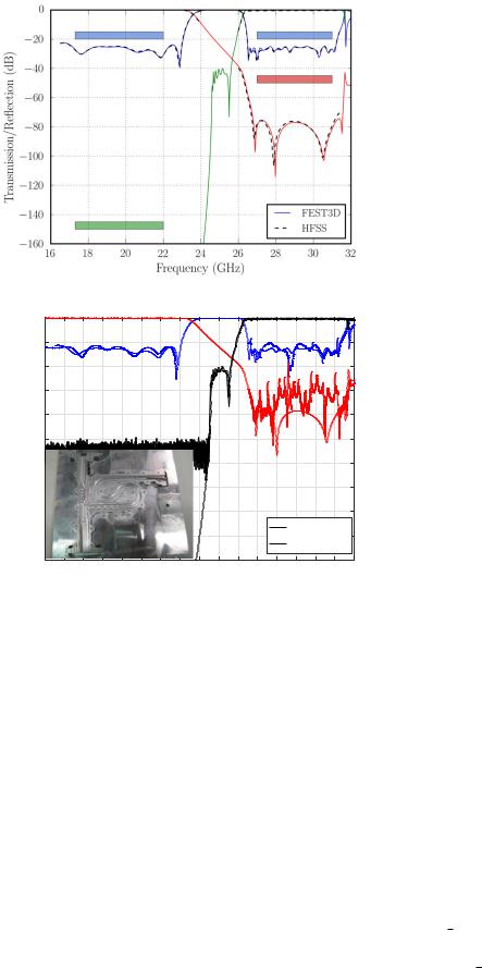
Fig. 3. Comparison of FEST3D simulated response with HFSS response (design masks included for reference) in (a), and with measurements in (b).
Using a high-pass section without band-pass filter, would have required about 125 mm. The size shrinkage could have been pushed further by reducing the width of the filter resonators to 6.1 mm. However, this possibility was not exploited in the design since we had no severe limitation in length or losses.
III. PIM DIPLEXER RESULTS
The filters for the downlink (input power) and the uplink (PIM) channel have been combined using a wideband E-plane T-junction, since it provides a higher bandwidth than H-plane ones, and also allows for low-PIM clam-shell manufacturing (with two identical halves), without interrupting current lines. The high-pass filter section has been meandered for compactness reasons while keeping the PIM port in a proper position. An additional section was added at the beginning of the lowpass filter to improve its adaptation to the diplexer junction. The design has been carried out using CST FEST3D software,
as the topology can be analyzed efficiently and accurately with advanced modal methods.
The measured scattering parameters of the hardware for TE10 excitation at the common port are shown in Fig. 3a. The agreement between CST FEST3D and Ansys HFSS responses is indeed excellent, fully validating the complete design.
The diplexer has been manufactured in aluminum, without any tuning elements. The measured response is shown in Fig. 3b. The response in the monomode region of the WR51 input port agrees very well with the simulated response (the small deviations can be attributed to manufacturing tolerances). On the other hand, there are spikes in the isolation response between the common port and the downlink port in the uplink band. These spikes are related to the transmission path provided by the TE20 mode, which is excited by (even small) misalignment in the hardware. Fortunately, however, the spikes are not a problem for the intended application of the diplexer, and could be easily removed by properly adjusting the width of the band reject filter or the input port [6], at the expense of a somewhat poorer power-handling and insertion loss performances.
For the downlink band (input power), the measured return loss was better than 22.5 dB and the insertion losses lower than 0.15 dB. The simulated power-handling capability was several dB above the requirements of 270 W. In the uplink band, the return loss satisfied the specification of 20 dB (see Table I), whereas the insertion loss was in the range between 0.45 and 0.6 dB due to the long meandered high-pass section. It is important to note that the use of a band-pass filter does reduce the size of the high-pass section, but at the cost of slightly increased insertion losses. Measurements carried out with a spectrum analyzer proved that the isolation between the common port and the uplink port was above 160 dB in the ITU downlink band.
IV. CONCLUSSIONS
A novel wideband diplexer for PIM measurement setups at Ka-band has been proposed. The design has been optimized to cover the complete Ka-band ITU spectrum allocation. The structure contains a band-reject filter which has been designed for an optimized performance of both the downlink passband (input power), and the uplink rejection band (PIM). The diplexer also includes a band-pass filter in the high-pass section, to improve compactness and to simplify the common junction optimization. In addition to design guidelines, the simulated response obtained with several EM simulators has been presented. The EM simulations show very good agreement with the measured performance of an aluminum prototype, thereby fully validating the proposed topology.
REFERENCES
[1]R. Mehrotra. (Sept. 2011). Regulation of global broadband satellites (GSR advanced copy for discussion). [Online]. Available: http://www.itu.int/ITU-D/treg/Events/Seminars/GSR/GSR11/documents/
BBReport BroadbandSatelliteRegulation-E.pdf
[2] J. Christensen. (Aug. 2012). ITU regulation for Ka-band satellite networks. [Online]. Available: https://www.itu.int/md/R12-ITURKA. BAND-C-0001/ page.print
1108
[3]P. Soto, D. Smacchia, C. Carceller, V.E. Boria, and M. Guglielmi, “Computer-aided design (CAD) of filters and multiplexers for passive inter-modulation (PIM) set-ups” in 2016 IEEE MTT-S Latin America Microw. Conf., Puerto Vallarta, Mexico, Dec. 2016, 3 pp.
[4]F. Arndt, J. Dittloff, U. Papziner, D. Fasold, N. Nathrath, and H. Wolf, “Rigorous field theory design of compact and lightweight broadband diplexers for satellite communication systems,” in 1989 Eur. Microw. Conf., London, UK, Sept. 1989, pp. 1214–1219.
[5]L. Accatino, “Computer-aided design of a Ku-band antenna diplexer,” in 1993 Eur. Microw. Conf., Madrid, Spain, Sept. 1993, pp. 544–546.
[6]J. Wang, B. Du, Y. Wu, and Y.-R. He, “A wideband waveguide diplexer for the extend C-band antenna systems ,” Progress in Electromagnetic Research C, vol. 69, pp. 73–82, 2016.
[7]U. Rosenberg, A. Bradt, M. Perelsthein, and P. Bourbonnais, “Extreme broadband waveguide diplexer design for high performance antenna feed systems,” in 2010 Eur. Microw. Conf., Paris, France, Sept. 2010, pp. 1249– 1252.
[8]P. Cecchini, R. Mizzoni, R. Ravanelli, G. Addamo, O. Peverini, R. Tascone, G. Virone, “Wideband diplexed feed chains for FSS + BSS applications,” in 2009 Eur. Conf. Antennas Propag., Berlin, Germany, Mar. 2009, pp. 3095-3099.
[9]J. Esteban and J. M. Rebollar, “Design and optimization of a compact Kaband antenna diplexer,” in 1995 IEEE Antennas Propag. Soc. Int. Symp., Newport Beach, CA, June 1995, pp. 148–151.
[10]F. de Paolis, R. Goulouev, J. Zheng, and M. Yu, “CAD procedure for high-performance composite corrugated filters,” IEEE Trans. Microw. Theory Techn., vol. 61, no. 9, pp. 3216–3224, 2013.
[11]F. Teberio, I. Arregui, A. Gomez-Torrent, E. Menargues, I. Arnedo, M. Chudzik, M. Zedler, F.-J. Gortz,¨ R. Jost, T. Lopetegi, and M. A. G. Laso, “High-power waveguide low-pass filter with all-higher-order mode suppression over a wide-band for Ka-band satellite applications,” IEEE Microw. Wireless Comp. Lett., vol. 25, no. 8, pp. 511–513, 2015.
[12]C. Carceller, P. Soto, V. E. Boria, M. Guglielmi, and J. Gil, “Design of compact wideband manifold-coupled multiplexers,” IEEE Trans. Microw. Theory Techn., vol. 63, no. 10, pp. 3398–3407, 2015.
1109