

диафрагмированные волноводные фильтры / 4db54ec6-bba9-488f-af4e-4dedc8a61d08
.pdf3040 |
IEEE TRANSACTIONS ON ANTENNAS AND PROPAGATION, VOL. 60, NO. 6, JUNE 2012 |
and amplitude distributions, respectively. By optimizing the weights of these basis functions, we are able to achieve the mainlobe shaping, sidelobe notch and the slop of the mainlobe. This algorithm is applicable to not only linear array but also planar array. Good results have been obtained with a small number of optimized variables. Furthermore, the method usually required less CPU time and reduced the DRR as compared to the adaptive GA. In addition, the idea of the algorithm can be applied to PSO.
ACKNOWLEDGMENT
The authors would like to thank the anonymous reviewers and Associate Editor for their competent and helpful suggestions to improve this communication.
REFERENCES
[1]C. Balanis, Antenna Theory-Analysis and Design. New York: Wiley, 1982.
[2]A. Safaai-Jazi, “A new formulation of the design of Chebyshev arrays,” IEEE Trans. Antennas Propag., vol. 42, pp. 439–443, Mar. 1994.
[3]A. Safaai-Jazi, “Directivity of Chebyshev arrays with arbitrary element spacing,” Electron. Lett., vol. 31, pp. 772–774, May 1995.
[4]J. M. Cid, J. A. Rodríguez, F. Ares, and E. Moreno, “Synthesis of satellite footprints by perturbation of Woodward-Lawson solutions for planar array antennas,” J. Electromagn. Waves Applicat., vol. 14, pp. 3–10, 2000.
[5]F. J. Ares-Pena, J. A. Rodriguez-Gonzalez, E. Villanueva-Lopez, and S. R. Rengarajan, “Genetic algorithms in the design and optimization of antenna array patterns,” IEEE Trans. Antennas Propag., vol. 47, no. 3, pp. 506–510, Mar. 1999.
[6]D. Marcano and F. Duran, “Synthesis of antenna arrays using genetic algorithms,” IEEE Antennas Propag. Mag., vol. 42, June 2000.
[7]M. Shimizu, “Determining the excitation coefficients of an array using genetic algorithm,” in Proc. IEEE Antenna Propag. Soc. Int. Symp., Seattle, WA, June 1994, vol. 1, pp. 530–533.
[8]F. J. Villegas, “Parallel genetic-algorithm optimization of shaped beam coverage areas using planar 2-D phased array,” IEEE Trans. Antenna Propag., vol. 55, no. 6, pp. 1745–1753, 2007.
[9]K. K. Yan and Y. Lu, “Sidelobe reduction in Array-Pattern synthesis using genetic algorithm,” IEEE Trans. Antennas Propag., vol. 45, no. 7, pp. 1117–1122, 1997.
[10]R. V. Gatti, L. Marcaccioli, and R. Sorrentino, “A novel phase-only method for shaped beam synthesis and adaptive nulling,” in Proc. 33rd Eur. Microwave Conf., Munich, 2003, pp. 739–742.
[11]D. W. Boeringer, D. H. Werner, and D. W. Machuga, “A simultaneous parameter adaptation scheme for genetic algorithms With application to phased array synthesis,” IEEE Trans. Antennas Propag., vol. 53, no. 1, pp. 2142–2145, Jan. 2005.
[12]T. H. Ismail and Z. M. Hamici, “Array pattern synthesis using digital phase control by quantized particle swarm optimization,” IEEE Trans. Antennas Propag., vol. 58, no. 6, pp. 2142–2145, Jun. 2010.
[13]D. W. Boeringer and D. H. Werner, “Particle swarm optimization versus genetic algorithms for phased array synthesis,” IEEE Trans. Antennas Propag., vol. 52, no. 3, pp. 771–779, Mar. 2004.
[14]J. A. Rodríguez, L. Landesa, J. L. Rodíguez, F. Obelleiro, F. Ares, and A. García-Pino, “Pattern synthesis of array antennas with arbitrary elements by simulated annealing and adaptive array theory,” Microw. Opt. Technol. Lett., vol. 20, pp. 48–50, Dec. 1999.
[15]Trastoy, F. Ares, and E. Moreno, “Phase-only control of antenna sum and shaped patterns through null perturbation,” IEEE Antennas Propag. Mag., vol. 43, no. 6, pp. 46–54, Dec. 2001.
[16]W. P. M. N. Keizer, “Fast low-sidelobe synthesis for large planar array antennas utilizing successive fast Fourier transforms of the array factor,” IEEE Trans. Antennas Propag., vol. 55, pp. 715–722, Mar. 2007.
[17]Y. Rahmat-Sand and E. Michielsen, Genetic Algorithms in Engineering Electromagnetics. New York: Wiley-Interscience, 1999.
[18]K. Deb, D. Joshi, and A. Anand, “Real-coded evolutionary algorithms with parent-centric recombination,” Proc. Evol. Comput., vol. 1, pp. 61–66, 2002.
Filter-Antenna Consisting of Conical FSS Radome and
Monopole Antenna
Hang Zhou, Shaobo Qu, Baoqin Lin, Jiafu Wang, Hua Ma,
Zhuo Xu, Weidong Peng, and Peng Bai
Abstract—A filter-antenna consisting of a monopole antenna and a conical frequency selective surface (FSS) radome was designed and investigated. A coupled-resonator spatial filter (CRSF) was used to design an FSS array with stable performances, and then a specific geometrical layout was proposed to construct a conical FSS radome. We technically investigated the combination of a monopole antenna and the conical FSS radome. Both the simulated and measured results show that the proposed filter-antenna keeps the input reflection coefficient, radiation pattern of the monopole antenna within the designed passband, and reflects out-of-band signals. Such properties of the filter-antenna will exhibit anti-interference capability and low RCS, which can be widely used in military applications.
Index Terms—Antenna, filter-antenna, frequency selective surface (FSS), radome.
I. INTRODUCTION
Frequency selective surface (FSS) is a periodic assembly of oneor two-dimensional resonant structures, either as apertures in a thin conducting sheet or as metallic patches on a substrate, correspondingly with a band-pass or band-stop function, respectively. FSSs have been widely used as polarizers, filters, subreflectors in dual-frequency antennas, absorbers and so on [1]–[6]. Another important application of FSS is hybrid-radome for radar cross-section (RCS) control and anti-in- terference. In this case, when the FSS is transparent to electromagnetic waves, transmission of the antenna signal is not affected at all. In contrast, when it is opaque, the signal is reflected. For the latter, when the radome is exposed to an incident field, most of the signal energy will be reflected in the bi-stastic direction because of the radome’s shape, leading to a very weak signal in the backscattering direction and thus to a low RCS [1]. In addition, this anti-interference capability will protect the antenna because strong electromagnetic interference (EMI) signals will also be stopped outside the operating band. Such advantages of the hybrid FSS radomes make it attractive in many practical applications. An important step is to design FSS structures with high selectivity, low insertion losses in the passband, as well as stable performances for different incidence angles and polarizations.
For decades, many methods have been adopted to improve the performance of FSS. Ben A. Munk et al. studied the effects of dielectric loading on FSS [7]. Three-dimensional structures were designed to
Manuscript received April 09, 2011; revised October 31, 2011; accepted November 11, 2011. Date of publication April 12, 2012; date of current version May 29, 2012. This work is supported in part by the National Natural Science Foundation of China under Grants.60871027, 60901029, National Basic Research Program of China under Grant 2009CB623306, Research Fund of Shaanxi Key Laboratory of Electronic Information System Integration (No. 201114Y11), and part by the Natural Science Foundation of Shaanxi Province of China under Grant No. 2011JQ8031.
H. Zhou, S. Qu, B. Lin, J. Wang, and H. Ma are with the College of Science, Air Force Engineering University, Xi’an 710051, China (e-mail: zh_cn1120@163.com; qushaobo@mail.xjtu.edu.cn).
Z. Xu is with the Electronic Materials Research Laboratory, Key Laboratory of the Ministry of Education, Xi’an Jiaotong University, Xi’an 710049, China.
W. Peng and P. Bai are with the Synthetic Electronic Information System Research Department, Air Force Engineering University, Xi’an 710051, China.
Color versions of one or more of the figures in this communication are available online at http://ieeexplore.ieee.org.
Digital Object Identifier 10.1109/TAP.2012.2194648
0018-926X/$31.00 © 2012 IEEE

IEEE TRANSACTIONS ON ANTENNAS AND PROPAGATION, VOL. 60, NO. 6, JUNE 2012 |
3041 |
obtain isotropic FSS [8]. Complementary FSSs have been analyzed in [9]–[11]. Miniaturized FSS, whose dimensions were much smaller than the operating wavelength, were investigated in [12]–[21]. Coupled-res- onator spatial filter (CRSF) FSS was firstly proposed in [22] and further studied in [23]–[26], in which two patches are coupled through an aperture to form a higher-order bandpass filter. Such FSSs possess high selectivity and flat passband in their operating frequencies. To achieve high Q-factor from open resonators, substrate integrated waveguide (SIW) technology was introduced by Luo et al. [27], [28] to design high-performance FSS.
Nevertheless, there are few literatures on integrated design of antennas and FSS. Multilayer FSS combined with open-ended waveguide radiator arrays was presented in [29]–[31], in which only filtering performances were analyzed using the multimode equivalent network method. Active FSS integrated with a horn antenna was discussed in [32]. A filter-antenna consisting of horn antenna and SIW-FSS was proposed in [33], in which the filtering and radiation performances were investigated. A symmetric dual-layer FSS radome, which was integrated on the radiation surface of a planar slotted waveguide antenna, was realized in [34]. The coupling between miniaturized FSS and patch antenna array for angle-independent, high-order spatial filtering was discussed in [35]. The aforementioned filter-antennas are mostly concentrated on planar FSS radomes. While in modern military applications, filter-antennas with conformal FSS radomes are much more attractive for better aerodynamic performances. Ben A. Munk et al. [36] designed a streamlined metallic FSS radome using arrays of slots etched into a solid metal curved radome. The radome permits transmission with any polarization over a wide range of scan angles. Band-pass characteristics of the radome were discussed. While for an integrated design of antenna and FSS radome, the filtering performances in suppressing out-band interferences and in reducing RCS are also important and are worthy to be investigated and discussed.
It is quite popular for researchers to use commercial software to make designs before practical experiments, because this lowers the cost and avoids many potential risks. However, a strict periodic array mounted on sharply curved surfaces is difficult to be constructed. Moreover, the simulation of a conformal FSS radome is not easy because of large amounts of computation. In this communication, we propose a specific geometrical layout to construct a conical FSS radome. Symmetrical boundary conditions are used to reduce the calculation. We technically investigate the combination of a monopole antenna and the conical FSS radome. Firstly, we used a CRSF structure to design a FSS array which exhibits high selectivity and stable performances for different incidence angles and polarizations at around 6.0 GHz. Such a FSS is a good candidate for designing FSS radomes. Secondly, a specific geometrical layout was proposed to shape a conical FSS radome. Finally, a filter-antenna consisting of a monopole antenna and a FSS radome was investigated and experimentally verified. Both the simulated and measured result show that such a filter-antenna exhibits the same radiation performance of the monopole antenna within the designed passband and has the filtering performance for out-of-band interference suppression and RCS reduction.
II. DESIGN PROCEDURE
A. CRSF-FSS Design
The coupled-resonator spatial filter FSS was first proposed in [22], in which two patches were coupled by an aperture. Dimensions of patches and of the aperture determine the resonant frequency and the coupling degree, respectively. By adjusting the size of the aperture, FSS with a second-order bandpass response can be obtained. Besides, circular patches are shaped by only one parameter, so it is easier to design a
Fig. 1. Configuration of the CRSF-FSS (left panel) and its unit cell (right panel).
Fig. 2. Frequency responses of the CRSF-FSS with different polarizations and incident angles. (a) Reflection and (b) transmission.
second-order CRSF structure. Under these considerations, in this communication, we choose two circular patches and a coupling circular aperture to construct the CRSF structure unit cell.
The proposed CRSF is shown in Fig. 1. It is composed of three metallic layers separated from one another by two thin dielectric layers. The top and bottom metallic layers of the unit cell have a circular patch in the center and the middle metallic layer is etched with a circular aperture in the center. Optimized dimensions of the unit cell in Fig. 1 are:
, , where
is the periodicity of the unit cell in - and -directions. The structure is based on two-layered Rogers 5870 substrate with the same periodic metallic patterns. The Rogers 5870 substrate has a thickness of 0.381 mm, loss tangent of 0.0012 and a dielectric constant of 2.33.
We used the High Frequency Structure Simulator (HFSS) version 12.0 [37], to calculate its reflection and transmission characteristics. Suppose the CRSF-FSS is an infinite periodic structure. The single CRSF-FSS is excited by an incident plane wave with different incident angles and polarizations. The four sides of the unit cell are set to be periodic boundary conditions (PBC). Fig. 2 gives the frequency responses under different incidence angles and polarizations. For normal incidence, we see from Fig. 2(b) that two pole transmission responses occur at about 6.0 GHz and 6.10 GHz, respectively. The 3 dB bandwidth is about 0.26 GHz (5.90–6.17 GHz). Moreover, the passband is rather flat without any ripples. Insertion loss in the passband is about
0.6 dB.
As a space filter, it is necessary that FSS provide stable performances for different incidence angles and polarizations. From Fig. 2 we can find that the insertion loss increases slightly as the incident angle increases for both TE and TM polarizations. For TM polarization, the insertion loss is still below 1 dB as the incident angle increases from 0 to 45 . While for TE polarization, when the incident angle increases to 45 , a ripple emerges in the passbands and the insertion loss is about 1.5 dB. With the aim to reduce the insertion loss, we simulated the case with both lossless spacers and perfect electric conductors. We find that

3042 |
IEEE TRANSACTIONS ON ANTENNAS AND PROPAGATION, VOL. 60, NO. 6, JUNE 2012 |
Fig. 3. Transmissions of the CRSF-FSS with/without loss, as well as with improved parameters for TE 45 .
.
Fig. 4. Configuration of conical radome. (a) Fan-shaped planar FSS. Ratio of the radius d to the center arc is . (b) Simulated model of the filter-antenna using HFSS.
the transmission loss is about 0.35 dB due to impedance mismatching of the FSS, as shown in Fig. 3. On this basis, we improved the FSS by taking . Then the transmission loss is about 1.32 dB, a reduction by 0.18 dB. The frequency response is rather stable under oblique incidence angles from 0 to 45 for both TE and TM polarizations. The CRSF-FSS owns its advantages to high selectivity, low insertion loss, stable performances, easy fabrication, so it is a good candidate for designing conical FSS radomes.
B. Conical FSS Radome Design
The CRSF-FSS is used to construct a conical FSS radome. For a miniature FSS radome, a strict periodic array mounted on sharply curved surfaces is difficult to be constructed. Because of this, we choose the FSS radome as a conical structure. For a conical radome, it can be spread as a fan-shaped planar FSS. The fan-shaped planar FSS is defined by two parameters: one is the length of the center arc and the other is the radius, as shown in Fig. 4(a). To keep the axi-symmetry of the FSS, the ratio of the radius to the center arc is chosen as
. The height of the designed conical FSS radome is 99.56 mm and its half angle is 41.04 , as shown in Fig. 4(b).
C. Filter-Antenna Design
The filter-antenna consisting of a monopole antenna and a conical FSS radome is shown in Fig. 4(b). To keep the axi-symmetry of the whole structure, the monopole antenna is laid on the center axis of the conical FSS radome. The filter-antenna was simulated by HFSS version 12.0. To reduce the simulation time, we set the two side faces of a quadrant computation region to be perfect magnetic conductors
Fig. 5. Simulated input reflection coefficient of the filter-antenna and monopole antenna.
(PMCs). In this way, we can get the accurate results by only calculating a quadrant of the filter-antenna.
The monopole antenna with a reflecting ground plane operating at 6.1 GHz was designed. The length of the monopole is 11.3 mm, and it is fed by a 50 coaxial cable. An IBM workstation with an Intel (R) Xeon (R) 5130 CPU and 16.0 G RAM was used. The solution time is about 53 minutes. Simulated of the filter-antenna and the monopole antenna are shown in Fig. 5. It can be found that 10 dB bandwidth of the monopole antenna is from 5.60 to 6.85 GHz and the input reflection coefficient at 6.1 GHz is 19.43 dB.
When the CRSF-FSS radome is installed in front of the monopole, the input reflection coefficient of the filter-antenna is then greatly changed. Input matching bandwidth of filter-antenna is much narrower. Two rapid roll-off edges occur at about 5.80 and 6.20 GHz. But the input reflection coefficient is still less than 10 dB in frequency range from 5.90 to 6.175 GHz. The value of the input reflection coefficient at 6.1 GHz is 16.22 dB. Out of this band most of the energy is reflected. This bandwidth of the input reflection coefficient agrees with the desired 3 dB passband (5.90–6.17 GHz) of the CRSF-FSS.
By calculating a quadrant of the filter-antenna using HFSS (see Fig. 4(b)), max directivity of the filter-antenna occur at . Thus, we compare the monopole antenna and the filter-antenna radiation patterns with at different frequencies as shown in Fig. 6. The radiation pattern of the monopole antenna and the filter-an- tenna at 6.1 GHz with is shown in Fig. 6(a). Though there are some minor differences between them, the filter-antenna radiation performance is nearly the same as that of the monopole antenna. Consequently, at 6.1 GHz, the filter-antenna with FSS radome has less influence on the antenna radiation performance.
In order to prove the anti-interference performances of the filter-an- tenna outside the band, another two monopole antennas operating at 5.5 GHz and 7.5 GHz were designed with the same FSS radome. The length of the monopole antenna operating at 5.5 GHz is 12.5 mm and its input reflection coefficient is 17.5 dB. Calculated input reflection coefficient of the filter-antenna consisting of 5.5 GHz monopole antenna and FSS radome is 0.98 dB. Radiation patterns with of the monopole antenna and the corresponding filter-antenna at 5.5 GHz is shown in Fig. 6(b). From this pattern, we can see that radiation of the filter-antenna has been restrained because of the presence of the FSS radome. The same phenomenon can also be obtained at 7.5 GHz. The length of the monopole operating at 7.5 GHz is 9.2 mm, and its input reflection coefficient is 18.3 dB. Calculated input reflection coefficient of the filter-antenna consisting of the 7.5 GHz monopole antenna and FSS radome is 0.04 dB. Radiation patterns with

IEEE TRANSACTIONS ON ANTENNAS AND PROPAGATION, VOL. 60, NO. 6, JUNE 2012 |
3043 |
Fig. 6. Radiation patterns of the monopole antenna and the corresponding filter-antenna at different frequencies with  . (a) 6.1 GHz, (b) 5.5 GHz, (c) 7.5 GHz.
of the monopole antenna and the corresponding filter-antenna at 7.5 GHz is shown in Fig. 6(c). Side and back lobes in the case with FSS radome are caused by power loss introduced by the insertion loss of the FSS radome. This will cause a little boresight error and reduce the antenna’s efficiency. From this pattern, we can see that radiation of the filter-antenna is also restrained. According to reciprocal principle, when the filter-antenna is used in receiving state, only the signals in the desired band can be completely received, while out of band signals are effectively reflected. This means the filter-antenna has the capability of anti-interference.
D. Monostatic RCS Results
Using HFSS, a plane wave for normal incidence is excited to simulate the monostatic RCSs of the antenna with such a FSS radome and with just a dielectric radome, as shown in Fig. 7. The dielectric radome is composed of two substrates used in Section II. RCS of the antenna with such a dielectric radome increases gradually as the frequency increases, while RCS of the antenna with the FSS radome decreases significantly. But at around 6.0 GHz the RCS for the radome case is higher. This is because most of the out-of-band signal energy will be reflected elsewhere due to the radome’s shape, leading to a very weak signal in the backscattering direction and thus to a low RCS. While at round 6.0 GHz in the pass-band, the incident angle to the FSS surface is about 50 . From Fig. 2, we know that as the incident angle increases, the insertion loss for TE polarization increases. This will affect the band-pass performance, but there is still partial energy entering the radome and reflected by the antenna ground. Thus, at around 6.0 GHz, the RCS of antenna with FSS radome is a little higher but still quite lower than that of the antenna with dielectric radome. From these results, we found that the monstatic RCS of the antenna can be effectively reduced with the aid of such a FSS radome.
III. EXPERIMENT
An experiment was carried out to verify our design. The proposed CRSF-FSS was fabricated by using two Rogers 5870 substrates, whose permittivity is 2.33 and loss tangent 0.0012. Then fan-shaped planar
Fig. .7. Compared monostatic RCS results.
Fig. 8. Prototype of the fabricated radome and antenna. (a) Conical FSS radome and (b) monopole antenna operating at 6.1 GHz.
FSS were adhered and rolled to form a conical FSS radome as shown in Fig. 8(a). A monopole antenna with a circular metallic ground plane operating at 6.1 GHz was also fabricated, as shown in Fig. 8(b). The radius of the metallic ground is 86.67 mm which is equal to the bottom radius of the conical FSS radome.
A. Filtering Performance Measurement
The input reflection coefficients of the monopole antenna and the corresponding filter-antenna were measured by HP 8720ES network analyzer, as plotted in Fig. 9.
The measured input reflection coefficient of the monopole antenna is lower than 10 dB within a frequency range from 5.52 to 6.86 GHz, in good agreement with the simulated results. The monopole antenna was covered with the FSS radome to construct a filter-antenna. The measured input reflection coefficient of the filter-antenna agrees well with the simulated results. However, the measured bandwidth of the passband (5.78–6.25 GHz) is a little wider than the simulated one (5.90–6.175 GHz). This discrepancy can be attributed to some factors. Firstly, the planar CRSF-FSS can be easily fabricated by printed circuit board (PCB) technology. However, the two fan-shaped planar FSS
3044 |
IEEE TRANSACTIONS ON ANTENNAS AND PROPAGATION, VOL. 60, NO. 6, JUNE 2012 |
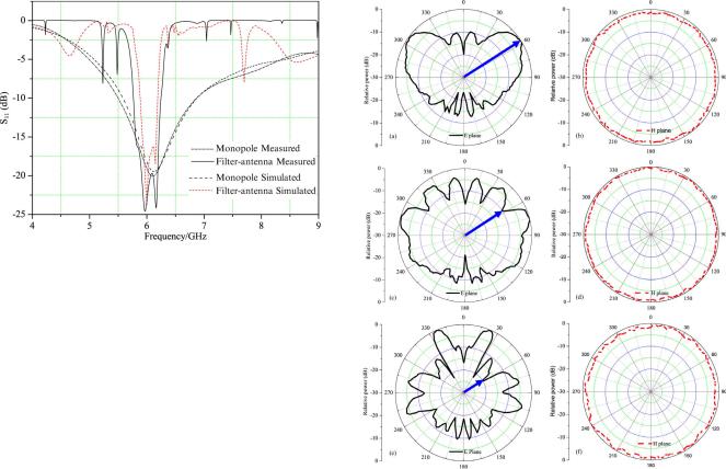
Fig. 9. Comparison between measured and simulated input reflection coefficients of filter-antenna and monopole antenna.
were adhered and rolled to form a conical FSS radome by our handwork, so there are some discrepancies. Secondly, in simulations the FSS radome is put in front of the monopole antenna seamlessly, but in experiment there is a small gap between the reflecting ground plane and the radome. The FSS radome is not well matched with the reflecting ground. Thirdly, fabrication precision of the filter-antenna can also lead to such discrepancy.
B. Radiation Performance Measurement
In order to reduce the simulation time, we used HFSS to simulate a quadrant of the filter-antenna and the two side faces of the quadrant region were set to be PMC. In this way, calculated radiation patterns were different from the results obtained by simulating the whole filter-an- tenna [37]. Nevertheless, the input reflection coefficients are the same. Thus, the measured and simulated patterns cannot be directly compared because of the beam tilted by HFSS modeling. However, we can still plot the experimental radiation patterns.
Fig. 10 gives the normalized measured radiation patterns of the filterantenna at different frequencies. From Fig. 10, we find that good radiation patterns are kept at 6.1 GHz in the passband of the FSS. In the E-plane, the metallic ground makes the beam tilt and the maximum directivity occurs at . While in the H plane, it keeps good omnidirectional patterns, very similar to a monopole antenna’s radiation patterns. For both 5.5 GHz and 7.5 GHz out of the passband, the radiation performance is degraded. Directivities decrease at around
in E plane and the levels of side lobes and back lobes increase.
From the measured input reflection coefficient of the filter-antenna, it is found that the designed filter-antenna has desired filtering performances, including anti-interference capability. Also, because of the conical FSS radome, a low RCS would be obtained out of band in the backscattering direction.
IV. DISCUSSION
The filter-antenna has both a good radiation performance of monopole antenna within the designed band and excellent filtering performance. Nevertheless, it still needs to be improved in further studies. Because phased array antennas are more widely used than monopole antennas in military applications, it is necessary that the FSS radomes keep good filtering performance for various scan angles. In this case, dielectric slabs with a thickness of about and
should be added on the surface [1]. FSS with stable performance
Fig. 10. Normalized measured radiation patterns of filter-antenna at different frequencies. (a) E plane at 6.1 GHz, (b) H plane at 6.1 GHz, (c) E plane at 5.5 GHz, (d) H plane at 5.5 GHz, (e) E plane at 7.5 GHz, (f) H plane at 7.5 GHz.
for large incident angles is still required. Conformal FSS radome is still needed to be designed and improved for better aerodynamic performances and for phased array antennas.
V. CONCLUSION
In this communication, a filter-antenna with a monopole antenna and a conical FSS radome was designed and experimentally verified. First, a CRSF-FSS structure was designed. Such CRSF-FSS has advantages of high selectivity, low insertion loss and stable performance, making it is a good candidate for designing hybrid FSS radomes. Then, a specific geometrical layout was presented to design a conical FSS radome. A filter-antenna was technically designed and investigated. In the end, an experiment was carried out to verify our design. The conical FSS and a monopole antenna with a big reflective ground plane operating at about 6.1 GHz were fabricated. Both the simulated and experimental measured results show that the filter-antenna exhibits an excellent filtering performance. At the designed band the filter-antenna can work as an antenna with good radiation performance nearly the same as that of monopole antenna. Out of band the interference signals and EMI can be effectively suppressed. The presented conical FSS radome provides practical military applications such as RCS reduction and electronic countermeasures.
REFERENCES
[1]B. A. Munk, Frequency Selective Surfaces: Theory and Design. New York: Wiley, 2000.
[2]T. K. Wu, Frequency Selective Surfaces and Grid Arrays. New York: Wiley, 1995.

IEEE TRANSACTIONS ON ANTENNAS AND PROPAGATION, VOL. 60, NO. 6, JUNE 2012
[3]S. A. Winkler, W. Hong, M. Bozzi, and K. Wu, “Polarization rotating frequency selective surface based on substrate integrated waveguide technology,” IEEE Trans. Antennas Propag., vol. 58, no. 4, pp. 1202–1213, 2010.
[4]S. Chakravarty, R. Mittra, and N. Rhodes, “Williams application of a microgenetic algorithm (MGA) to the design of broad-band microwave absorbers using multiple frequency selective surface screens buried dielectrics,” IEEE Trans. Antennas Propag., vol. 50, no. 3, pp. 284–296, 2002.
[5]G. I. Kiani, K. L. Ford, K. P. Esselle, A. R. Weily, and C. J. Panagamuwa, “Oblique incidence performance of a novel frequency selective surface absorber,” IEEE Trans. Antennas Propag., vol. 55, no. 10, pp. 2931–2934, 2007.
[6]A. K. Rashid and Z. Shen, “A novel band-reject frequency selective surface with pseudo-elliptic response,” IEEE Trans. Antennas Propag., vol. 58, no. 4, pp. 1220–1226, 2010.
[7]R. J. Luebbers and B. A. Munk, “Some effects of dielectric loading on periodic slot arrays,” IEEE Trans. Antennas Propag., vol. 26, no. 4, pp. 536–542, 1978.
[8]J. D. Baena, L. Jelinek, R. Marqués, J. J. Mock, J. Gollub, and D. R. Smith, “Isotropic frequency selective surfaces made of cubic resonators,” Appl. Phys. Lett., vol. 91, p. 191105, 2007.
[9]H. Wakabayashi, M. Kominami, H. Kusaka, and H. Nakashima, “Numerical simulations for frequency-selective screens with complementary elements,” Inst. Int. Eng. Proc.-Micro. Antennas Propag., vol. 141, no. 6, pp. 477–482, 1994.
[10]D. S. Lockyers, J. C. Vardaxpglou, and R. A. Simpkin, “Complementary frequency selective surfaces,” Inst. Int. Eng. Proc.-Micro. Antennas Propag., vol. 147, no. 6, pp. 501–507, 2000.
[11]R. Marqués, J. D. Baena, M. Beruete, F. Falcone, and T. Lopetegi et al., “Ab initio an analysis of frequency selective surface based on conventional and complementary split ring resonators,” J. Opt. A: Pure Appl. Opt., vol. 7, pp. 538–543, 2005.
[12]E. A. Parker and A. N. A. EI Sheikh, “Convoluted array elements and reduced size unit cells for frequency selective,” Inst. Int. Eng. Proc.- Micro. Antennas Propag., vol. 138, no. 1, pp. 19–22, 1991.
[13]E. A. Parker, A. N. A. EI Sheikh, and A. C. de C. Lima, “Convoluted frequency-selective array elements derived from linear and crossed dipoles,” Inst. Int. Eng. Proc.-Micro. Antennas Propag., vol. 140, no. 5, pp. 378–380, 1993.
[14]K. Sarabandi and N. Behdad, “A frequency selective surface with miniaturized elements,” IEEE Trans. Antennas Propag., vol. 55, no. 5, pp. 1239–1245, 2007.
[15]F. Bayatpur and K. Sarabandi, “Single-layer, high-order, miniaturized element frequency selective surfaces,” IEEE Trans. Microw. Theory Tech., vol. 56, no. 4, pp. 774–781, 2008.
[16]E. A. Parker, J.-B. Robertson, B. Sanz-lzquierdo, and J. C. Batchlor, “Minimal size FSS for long wavelength operation,” Electron. Lett., vol. 44, no. 6, 2008.
[17]H. Liu, K. L. Fprd, and R. J. Langley, “Miniaturized bandpass frequency selective surface with lumped components,” Electron. Lett., vol. 44, no. 18, 2008.
[18]R. R. Xu, Z.-Y. Zong, H.-C. Zhao, Z.-Y. Zong, and W. Wu, “Dualband capacitive loaded frequency selective surfaces with close band spacing,” IEEE Microw. Wireless Compon. Lett., vol. 18, no. 12, pp. 782–784, 2008.
[19]C.-N. Chiu and K.-P. Chang, “A novel miniaturized-element frequency selective surface having a stable resonance,” IEEE Antennas Wireless Propag. Lett., vol. 8, pp. 1175–1177, 2009.
[20]R.-R. Xu, Z.-Y. Zong, and W. Wu, “Low-frequency miniaturized dualband frequency selective surfaces with close band spacing,” Microw. Opt. Techn. Lett., vol. 51, no. 5, pp. 1238–1240, 2009.
[21]B. Sanz-lzquierdo, E. A. Parker, J.-B. Roberson, and J. C. Batchelor, “Singly and dual polarized convoluted frequency selective structures,” IEEE Trans. Antennas Propag., vol. 58, no. 3, pp. 690–696, 2010.
[22]R. Pous and D. M. Pozar, “A frequency-selective surface using coupled microstrip patches,” IEEE Trans. Antennas Propag., vol. 39, no. 12, pp. 1763–1769, 1991.
[23]A. A. Tamijani, K. Sarabandi, and G. M. Rebeiz, “Antenna-filter-an- tenna arrays as a class of bandpass frequency-selective surfaces,” IEEE Trans. Microwave Theory Tech., vol. 52, no. 8, pp. 1781–1789, 2004.
[24]N. Behdad, M. A. Joumayly, and M. Salehi, “A low-profile third-order bandpass frequency selective surface,” IEEE Trans. Antennas Propag., vol. 57, no. 2, pp. 460–466, 2009.
[25]M. Al-Joumayly and N. Behdad, “A new technique for design of lowprofile, second-order, band-pass frequency selective surfaces,” IEEE Trans. Antennas Propag., vol. 57, no. 2, pp. 452–459, 2009.
3045
[26]M. Al-Joumayly and N. Behdad, “A generalized method for synthesizing low-profile, band-pass frequency selective surfaces with non resonant constituting elements,” IEEE Trans. Antennas Propag., vol. 58, no. 12, pp. 4033–4041, Dec. 2010.
[27]G. Q. Luo, W. Hong, Z. C. Hao, B. Liu, and W. D. Li et al., “Theory and experiment of novel frequency selective surface based on substrate integrated waveguide technology,” IEEE Trans. Antennas Propag., vol. 53, no. 12, pp. 4035–4043, Dec. 2005.
[28]G. Q. Luo, W. Hong, Q. H. Lai, K. Wu, and L. L. Sun, “Design and experimental verification of compact frequency-selective surface with quasi-elliptic bandpass response,” IEEE Trans. Microw. Theory Tech., vol. 55, no. 12, pp. 2481–2487, 2007.
[29]H. J. Visser and M. Guglielmi, “Filter design of waveguide array antennas,” in IEEE AP-S Symp. Digest, Jul. 1997, vol. 4, pp. 2338–2341.
[30]S. Monni, N. L. Juan, A. Neto, and G. Gerini, “Phased array antenna integrated with a frequency selective surface—Theory and experiments,” in IEEE Int. Symp. Phased Array Systems and Technology Digest, 2003, pp. 458–463.
[31]G. Gerini and L. Zappelli, “Multilayer array antennas with integrated frequency selective surfaces conformal to a circular cylindrical surface,” IEEE Trans. Antennas Propag., vol. 53, no. 6, pp. 2020–2030, Jun. 2005.
[32]B. Philips, E. A. Parker, and R. J. Langley, “Active FSS an experimental horn antenna switchable between two beamwidths,” Electron. Lett., vol. 31, no. 1, 1995.
[33]G. Q. Luo, W. Hong, H. J. Tang, and J. X. Chen et al., “Filter-antenna consisting of horn antenna and substrate integrated waveguide cavity FSS,” IEEE Trans. Antennas Propag., vol. 55, no. 1, pp. 92–98, Jan. 2007.
[34]H. Chen, X. Hou, and L. Deng, “Design of frequency-selective surfaces radome for a planar slotted waveguide antenna,” IEEE Antennas Wireless Propag. Lett., vol. 8, pp. 1231–1233, 2009.
[35]F. Bayatpur and K. Sarabandi, “Miniaturized FSS and patch antenna array coupling for angle-independent, high-order spatial filtering,”
IEEE Microw. Wireless Compon. Lett., vol. 20, no. 2, pp. 79–81, 2010.
[36]E. L. Pelton and B. A. Munk, “A streamlined metallic radome,” IEEE Trans. Antennas Propag., vol. 22, no. 6, pp. 799–803, Nov. 1974.
[37]High Frequency Structure Simulator (HFSS) Ansoft Corporation [Online]. Available: www.ansoft.com