

диафрагмированные волноводные фильтры / 5d44426b-1fdf-41a1-8d9e-a82bc4121ec3
.pdfThis article has been accepted for publication in a future issue of this journal, but has not been fully edited. Content may change prior to final publication. Citation information: DOI 10.1109/TAP.2021.3061110, IEEE Transactions on Antennas and Propagation
SIW Cavity-Fed Filtennas for 5G Millimeter
WaveApplications
Rong Lu, Student Member, Chao Yu, Member, IEEE, Fan Wu, Member, IEEE,
Zhiqiang Yu, Member, IEEE, Liyu Zhu, Jianyi Zhou, Member, IEEE,
Pinpin Yan, Member, IEEE, and Wei Hong, Fellow, IEEE
Abstract—In this paper, novel millimeter wave (mmWave) filtennas (filtering antennas) are proposed to realize compact size and low insertion loss for 5G applications. It is achieved by employing eighth-mode substrate integrated waveguide (EMSIW) cavities fully shielded by metallized vias and cover as resonators, which are named as fully-shielded EMSIW (FSD-EMSIW) cavities. Interdigital coupling between cavities is introduced in order to obtain higher coupling strength for wideband operation. The proposed single-polarized antenna consists of a feeding stripline, two FSD-EMSIW cavities and two stacked square patches, generating the four-order filtering antenna response. Furthermore, this design has been extended to realize a dual-polarized filtenna by employing double sets of feeding network. For demonstration, single-/dual-polarized filtenna prototypes were fabricated and measured, the measured results show that the 5G mmWave band (24.25 - 29.5 GHz) can be covered with average gains of 4.5 dBi. Good bandpass filtering response is also observed. Finally, to validate the proposed idea in array applications, a 16-element filtenna array is designed and measured with good performance.
Index Terms—Filtenna, Filtering antenna, mmWave, 5G, dual-polarized antenna, array antenna, substrate integrated waveguide.
I. INTRODUCTION
W ITH the rapid development of modern communications, the mmWave bands have attracted intensive research interests in 5G applications to provide high data throughput and low latency [1], [2]. Massive MIMO antenna array is adopted to overcome the path loss and realize flexible beamforming in 5G mmWave applications [3]. Due to the limitationon the antenna elementspacing, the beamforming technique places the huge limitation on the size of the element and the integration with beamformer chip. Meanwhile, filters
Manuscript received September xx, 2020. This work was supported by the National Natural Science Foundation of China (NSFC) under Grant 61861136002 and 61627801. (Corresponding author: Wei Hong.)
Rong Lu, Chao Yu, Zhiqiang Yu, Jianyi Zhou and Wei Hong are with the State Key Laboratory of Millimeter Waves, Southeast University, Nanjing 210096, China, and also with the Purple Mountain Laboratories, Nanjing 211111, China (email: ronglu@seu.edu.cn; chao.yu@seu.edu.cn; zqyu@seu.edu.cn; jyzhou@seu.edu.cn; weihong@seu.edu.cn)
Fan Wu, Liyu Zhu and Pinpin Yan are with the State Key Laboratory of Millimeter Waves, School of Information Science and Engineering, Southeast University, Nanjing 210096, China (email: fan.wu@seu.edu.cn; 230198968@seu.edu.cn; yanpinpin@seu.edu.cn;).
are very important in mmWave front-ends to provide the out-of-band suppression and thus improve signal-to-noise ratio [4]-[6]. Therefore, it is very crucial to effectively integrate the functionality of antenna array and filters. One straightforward design approach is to cascade the separately designed filters and antennas [7]-[9]. However, this kind of approaches usually lead to high insertion loss and large area. To achieve high antenna performance and reduce the overall size for array applications, it is necessary to realize the so-called filtenna (filtering antenna).
A growing number of filtennas have been proposed in the last decade [10]-[24]. However, most of them were designed to work in low frequencies. One design method of the filtenna is to replace the last-stage of the band-pass filter by the radiating antenna [11]-[15]. Microstrip line resonator-fed filtennas for sub-6GHz applications have been reported in [12], [13]. Moreover, filtennas can also be designed using additional structures, such as parasitic patches [17]-[20], slots [21], [22], shorting pins [17], [20], and elaborate feeding structures [23], [24]. Very few techniques have been developed for mmWave applications. In [14], a 1 × 4 microstrip antenna subarray was realized by the vertically coupled resonant structure, including microstrip resonators, U-slot resonators and radiating patches. Thecombinationofadifferential-fedcross-shapeddrivenpatch, four stacked parasitic patches, four additional shorted patches, and cross-shaped strip realized a mmWave antenna with band-pass response in [20]. Among the published work, most designs are based on microstrip resonators, which may suffer from high insertion loss due to the open structure in mmWave frequency.Thecomplex microstrip feedingcircuits alsooccupy a relatively large area in the surface metal layer of PCB, which are not suitable for the integration with active beamformer chips [25], [26].
The substrate integrated waveguide (SIW) technology has drawn much attention due to its low loss, low cost, and ease of integration in mmWave band applications. Several mmWave filtennas were realized based on SIW cavities [27]-[29]. A SIW single-polarized filtenna element in [27] achieved a fractional bandwidthof1.56%. A1×2SIWsingle-polarizedfiltennaanda 2×2 SIW dual-polarized filtenna were presented in [28] and [29]. At first glance, the bulky size of SIW cavity might be not suitable for 5G mmWave massive MIMO antenna arrays. However, advanced techniques have been developed to reduce the resonator size to affordable level, such as half-mode SIW
0018-926X (c) 2021 IEEE. Personal use is permitted, but republication/redistribution requires IEEE permission. See http://www.ieee.org/publications_standards/publications/rights/index.html for more information.
Authorized licensed use limited to: Miami University Libraries. Downloaded on June 16,2021 at 21:53:24 UTC from IEEE Xplore. Restrictions apply.
This article has been accepted for publication in a future issue of this journal, but has not been fully edited. Content may change prior to final publication. Citation information: DOI 10.1109/TAP.2021.3061110, IEEE Transactions on Antennas and Propagation
(HMSIW) [30]-[32], quarter-mode SIW (QMSIW) [33], [34], and eighth-mode SIW(EMSIW) [35]-[37].The size ofEMSIW cavity is only about 12.5% of that of the traditional SIW cavity [35]. Thus, the SIW is one of the most promising technology for 5G applications. Nevertheless, the radiation effect of these miniaturized semi-open structures reaches a significant level at mmWave frequency.
To resolve this issue, novel mmWave filtennas are proposed in this paper to realize the compact size and low insertion loss. Eighth-mode substrate integrated waveguide (EMSIW) cavities shielded by metallized vias and cover are used as resonators because of the flexibility in controlling the resonant frequency and coupling strength, the compact size, and high quality factor, which are named as fully-shielded eighth-mode substrate integrated waveguide (FSD-EMSIW) cavities in our design. Interdigital coupling between FSD-EMSIW cavities is adopted in order to obtain higher coupling strength in the filtenna design. Furthermore, a 16-element antenna array is also designed for the validation in array applications. The simulation and measurement results demonstrate that the filtennas have a compact size and good filtering performance, which is suitable for 5G mmWave applications.
This paper is organized as follows. Section II introduces the characteristicsoftheFSD-EMSIWcavity, thedesignguideline, and measured results of the mmWave single-polarized filtenna. Section III presents a study of the dual-polarized filtenna. Section IV demonstrates the proposed filtenna in array applications. Finally, a brief conclusion is drawn in Section V.
II. SINGLE-POLARIZED FILTENNA ELEMENT
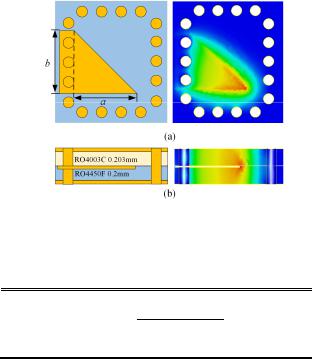
Because of the flexibility in controlling the resonant frequency and coupling strength, compact size, and high Q-factor, FSD-EMSIW cavity is adopted in the filtenna design. Compared with the traditional EMSIW cavity [35]-[37], the proposed structure is fully shielded with vias and top metal as shown in Fig. 1. One RO4003C layer (εr1 = 3.55, tanδ = 0.0027, and h = 0.203 mm), one RO4450F layer (εr2 = 3.52, tanδ = 0.004, and hb = 0.2 mm), and three metal layers (t = 35 μm) are used to form the cavity. The electric field is restricted in the cavity by the additional vias and metal. The resonant frequency of the proposed FSD-EMSIW cavity can be estimated by
f |
|
= |
|
|
c |
|
|
( |
π |
)2 + ( |
|
π |
)2 |
(1) |
|||
TE101 |
2π |
|
|
|
|
|
|
||||||||||
|
|
|
|
μ ε |
r |
|
|
a |
eff |
|
b |
eff |
|
|
|||
|
|
|
|
|
|
|
r |
|
|
|
|
|
|
|
|||
a = a |
|
+ |
|
d 2 |
|
- ∆w |
|
|
|
|
(2) |
||||||
|
0.95p |
|
|
|
|
|
|||||||||||
|
eff |
|
|
|
|
|
|
|
|
|
|
|
|
||||
b = b |
|
+ |
|
d 2 |
|
- ∆w |
|
|
|
|
(3) |
||||||
|
0.95p |
|
|
|
|
||||||||||||
|
eff |
|
|
|
|
|
|
|
|
|
|
|
|||||
εr = εr1 |
2 |
εr2 |
|
|
|
|
|
|
|
|
|
|
|
(4) |
|||
where fTE101 is the resonant frequency of the fundamental mode TE101, and are the relative permeability and permittivity
ofthe cavity substrate respectively, c is the light velocity offree
space. aeff and beff are the equivalent length and width of the shorted triangular patch. d and p are the diameter of the
metallized vias and the distance between the adjacent vias. ∆w represents the effect of fringing fieldofthe equivalent magnetic walls [30]. In this design, we use right-angled isosceles
Fig. 1. Configuration of the proposed FSD-EMSIW cavity: (a) top view and fundamental resonant mode electric field distribution, (b) side view and fundamental resonant mode electric field distribution.
TABLEI
COMPARISON OF UNLOADED QUALITY FACTORS AND SIZE OF THE
FSD-EMSIWCAVITY AND OTHER RESONATORS
|
FSD-EMSIW |
EMSIW |
SIW |
|
|
|
|
Qu |
183 |
65 |
203 |
Size* |
0.21 ×0.21 λ02 |
0.21 ×0.21 λ02 |
0.4 ×0.4 λ02 |
* λ denotes the wavelength at the resonant frequency.
triangular cavity, i.e., a = b.
The size and simulated unloaded quality factor [38] of the SIW cavity, the traditional and proposed EMSIW cavity have beenlistedinTableI.Thankstothefully enclosedstructure,the radiation loss of the FSD-EMSIW resonator is eliminated, and thus the Qu of the FSD-EMSIW cavity is larger than the traditional semi-open EMSIW cavity. In addition, it is very attractive to reduce the parasitic radiation from the feeding network in the antenna design.
The FSD-EMSIW cavities are adopted as resonators in the filtenna design because of the compact size and high Qu. Fig. 2 shows the configuration of the proposed single-polarized filtenna. In this design, the standard PCB process is adopted to reduce the fabrication cost. Fig. 2(a) shows the lamination stack-up of the antenna, which consists of three laminates, two bonding layers and six metal layers. TLY-5 (εr = 2.2 and tanδ = 0.0009), RO4003C, and RO4450F are used in this design. Two stacked square patches are realized on M1 and M2, while the antenna feeding network is routed on M3 to M6. The bottom metal layer M6 is also planned for the RF connector. Moreover, the ground of the stacked patch antenna and feeding network (on M3 and M5) are connected together by some blind vias. In this filtenna design, the feeding network mainly contains an input stripline and two fully-shielded eighth-mode substrate integrated waveguide (FSD-EMSIW) cavities (R1 and R2). The energy from the feeding network is coupled to the lower square patch (R3) on M2 through the coupling aperture on the shared ground plane M3, and then radiated from the upper square patch (R4). Since the lower patch on M2 is deeply buried in the substrates, the energy directly radiating from the lower patch to the free space can be neglected. As a result, a
0018-926X (c) 2021 IEEE. Personal use is permitted, but republication/redistribution requires IEEE permission. See http://www.ieee.org/publications_standards/publications/rights/index.html for more information.
Authorized licensed use limited to: Miami University Libraries. Downloaded on June 16,2021 at 21:53:24 UTC from IEEE Xplore. Restrictions apply.

This article has been accepted for publication in a future issue of this journal, but has not been fully edited. Content may change prior to final publication. Citation information: DOI 10.1109/TAP.2021.3061110, IEEE Transactions on Antennas and Propagation
Fig. 2. Configuration of the proposed single-polarized filtenna: (a) the lamination stack-up of the antenna, (b) geometry stack-up of the antenna, (c) top view of metal layer on M4, where b1 = 1.72, b2 = 1.31, d = 0.3, dis3 = 0.3,
dx23 = 0.1, dy23 = 0.14, l12 = 0.3, lgnd = 15, ls23 = 1.24, p = 0.55, pin = 1.07, w12 = 0.15, w50 = 0.16, wp3 = 2.5, wp4 = 2.72, ws12 = 0.12, ws23 = 0.35 (unit: mm).
filtennawith four-order band-pass responsecanbeachieved.Its corresponding coupling topology is given in Fig. 3.
The design guideline of the single-polarized filtenna will be discussed in the following sections.
A. External and Internal Coupling
The external quality factor Qext and internal coupling Mij of the proposed filtenna have a significant influence on its performance, which can be extracted by the equations in [39]. Theexternalquality factor Qext canbecontrolledbythelocation offeedlinepin. ThecouplingcoefficientM12 increases whenthe distance w12 between two FSD-EMSIW cavities decreases.
Fig. 3. Coupling topology of the single-polarized filtenna.
Fig. 4. Coupling coefficient M34 and antenna radiation Qrad with different top substrate thickness h.
However, the minimum distance between the two cavities is limited by current PCB processing technology. Interdigital coupling is used in order to obtain higher coupling strength with distance allowed by the design rule. Coupling coefficient M23 can be controlled by varying the length of the coupling aperture and its position. As for M34, a stronger coupling can be observed in the stacked patches when the thickness h of the top Taconic TLY-5 layer decreases.
B. Antenna Radiation Q
The upper patch is designed as both the last resonator and the radiator for the four-order filtenna. Therefore, the radiation factor Qrad should be equivalent to the external factor Qext of the equivalent filter. Qrad of the patch can be calculated using the following equations [40] by simulating a standalone patch antenna fed by a lumped port in the full-wave simulation.
S ϕ |
= |
1 + S11min 2 |
|
|
|
|
(5) |
|||
|
|
|
|
|
||||||
11 |
|
|
|
2 |
|
|
|
|
|
|
|
|
|
|
|
|
|
|
|
|
|
|
1 - S min |
|
|
|
|
|
|
|
||
k = |
11 |
|
(resonator is under coupled) |
(6) |
||||||
min |
||||||||||
|
1 + S11 |
|
|
|
|
|
coupled) |
|
||
k =1 + S11min |
(resonator is over |
(7) |
||||||||
|
1 - S11min |
|
f0 |
|
|
|
||||
Qrad = (1 + k) |
|
|
|
|
(8) |
|||||
f2 - f1 |
|
|
||||||||
where S min is the minimum reflection coefficient occurring at |
||||||||||
11 |
|
|
|
|
|
|
|
|
|
|
the resonant frequency |
f0 , f1 |
and f2 correspond to |
the |
|||||||
frequencies when S11= S11ϕ .
Fig. 4 shows Qrad is influenced by the thickness h of the top dielectric substrate. It is worth mentioning that its thickness also controls the coupling coefficient M34. Therefore, the top substrate thickness should be carefully chosen in the specific filtenna design.
C. Single-Polarized Antenna Performance
In order to meet the requirement of the 5G mmWave applications, the frequency specifications of the antenna
0018-926X (c) 2021 IEEE. Personal use is permitted, but republication/redistribution requires IEEE permission. See http://www.ieee.org/publications_standards/publications/rights/index.html for more information.
Authorized licensed use limited to: Miami University Libraries. Downloaded on June 16,2021 at 21:53:24 UTC from IEEE Xplore. Restrictions apply.

This article has been accepted for publication in a future issue of this journal, but has not been fully edited. Content may change prior to final publication. Citation information: DOI 10.1109/TAP.2021.3061110, IEEE Transactions on Antennas and Propagation
Fig. 5. Reflection coefficient and realized gain of the traditional and proposed antenna.
Fig. 7. Simulated gains of three different cases.
Fig. 8. Photograph of fabricated single-polarized filtenna.
Fig. 6. Configuration of the quasi-coaxial via transition: (a) side view of the transition, (b) top view on M3-M6. Case B: d = 0.3, dcut1 = 0.5, dcut2 = 1.2, dcut3
=1.2, dpad = 0.5, dpad2 = 0.5, dpin = 0.2, dvia = 0.8, w50 = 0.16(unit: mm), theta1 = 40°. Case C: d = 0.3, dcut1 = 0.5, dcut2 = 1.2, dpad2 = 0.5, dpin = 0.2, dvia = 0.8, w50
=0.16, wms = 0.41 (unit: mm), theta2 = 35°.
element are given as follows: f0 = 27 GHz, BW = 6 GHz
The coupling coefficients and the external quality factors with the in-band return loss better than 15 dB can be derived as follows:
Qrad = Qext = 5.3796,
M12 = 0.1782, M23 = 0.1428, M34 = 0.1782.
Using the extracted design parameters from the above section, the optimized geometrical dimensions are listed below Fig. 2. The simulated frequency responses of the stripline-fed filtenna are illustrated in Fig. 5. The simulated return loss is
better than 15 dB within the passband. Comparing with the conventional stripline-fed aperture coupled stacked patch antenna, the proposed filtenna exhibits the advantages of wider impedance bandwidth and better band-pass radiation performance. The simulated radiation efficiency of the filtenna is 88%, which is slightly less than that of the traditional stacked patch antenna (94%). This stripline-fed filtenna is named as Case A for the following comparison.
To measure antenna performance and integrate with active components, aquasi-coaxial via transition isused toconvert the stripline on M4 to sub-miniature push-on micro (SMPM) connector (Case B) or microstrip line (Case C) on M6 as shown in Fig. 6. The length of ground plane lgnd in Case C is extended to 35 mm in order to place the SOUTHWEST end-launch connector. In this transition design, several grounding vias are employed around the signal blind via to avoid energy leakage and weaken the discontinuity of the transition. Moreover, restricted by the PCB machine drilling process, via implementation between M4 and M6 is not available in this design. The blind vias between M3 and M6 are used for the transition. Notice that an anti-pad is etched on M3 to avoid a short circuit between the signal via and ground. As the comparisonbetweenthreedifferentcases showninFig.7,some energy leaked from the anti-pad on M3 influences the radiation performance, especially upper band rejection. Radiation from the microstrip line on M6 in Case C cannot be ignored, but the overall performance is still acceptable and can be fabricated to verify the filtenna design. The in-band broadside gains are lower comparing with the mmWave antenna element in [14] and [20], which is due to the extended ground size for placing the connector. Fig. 8 shows the photograph of the fabricated single-polarized filtenna (Case C).
Fig. 9 shows the simulated and measured reflection coefficient and realized gain of the single-polarized filtenna element (Case C), which includes the quasi-coaxial via transition, the microstrip line on M6 and the SOUTHWEST
0018-926X (c) 2021 IEEE. Personal use is permitted, but republication/redistribution requires IEEE permission. See http://www.ieee.org/publications_standards/publications/rights/index.html for more information.
Authorized licensed use limited to: Miami University Libraries. Downloaded on June 16,2021 at 21:53:24 UTC from IEEE Xplore. Restrictions apply.

This article has been accepted for publication in a future issue of this journal, but has not been fully edited. Content may change prior to final publication. Citation information: DOI 10.1109/TAP.2021.3061110, IEEE Transactions on Antennas and Propagation
Fig. 9. Simulated and measured reflection coefficient and realized gain of the single-polarized filtenna element.
Fig. 10. Normalized simulated and measured single-polarized filtenna radiation patterns at 27 GHz. (a) E-Plane, (b) H-Plane.
end-launch connector. The antenna element achieves a measured fractional -10 dB impedance bandwidth of 23.5% covering the 5G mmWave band (24.25 - 29.5 GHz). The slight offset of the measured bandwidth may be caused by the higher substrate dielectric constant than expected. It is observed that the proposed antenna has a flat antenna gain about 4.5 dBi from 24to 29.5 GHz.Outofthe workingband,the gaindropsrapidly over 20 dB at 21 and 33 GHz.
Fig. 10 shows the normalized simulated and measured coand cross-polarization radiation patterns in two orthogonal planes at 27 GHz. The normalized cross-polarizations are below –17 dB in both E- and H-plane. The measured patterns are slightly different from the simulation especially in E-plane, which is mainly caused by the reflection effect of the metallic connector and the feeding cable in the measurement.
III. DUAL-POLARIZED FILTENNA ELEMENT
Based on the above-mentioned design procedure, a dual-polarized filtenna is also designed. The top view of the proposed filtenna is shown in Fig. 11. Two coupling slots etched on M3 are arranged as T-type. Two sets of feeding networks are placed on M3 to M6. Both polarizations share the same two stacked patches on top two metal layers. Comparing with the single-polarized element, no additional metal layer is needed in the dual-polarized prototype. The occupied area of the antenna element is 0.35λc × 0.49 λc (λc is the wavelength of free space at the central frequency).
The proposed dual-polarized filtenna element is prototyped
Fig. 11. (a) Top view of the dual-polarized filtenna metal layer on M4. (b) Top view of the patches and apertures in the dual-polarized filtenna. Geometries of the proposed dual-polarized filtenna, d = 0.3, p = 0.55, lgnd = 35, w50 = 0.16,
Port 1: b1h = 1.73, b2h = 1.16, dis3h = 0.45, dx23h = 0.1, dy23h = 0.47, l12h = 0.3, ls23h = 1.5, linh = 0.8, pinh = 1.2, w12h = 0.15, wp3h = 2.52, wp4h = 2.7, ws12h = 0.11, ws23h = 0.35, Port 2: b1v = 1.71, b2v = 1.25, dis3v = 0.13, dx23v = 0.1, dy23v = 0.22, l12v = 0.3, ls23v = 1.34, linv = 0.8, pinv = 1.18, w12v = 0.15, wp3v = 2.51, wp4v = 2.72, ws12v = 0.11, ws23v = 0.35, (unit: mm). (c) Photograph of fabricated
dual-polarized filtenna. (d) Measurement setup in the far-field chamber.
Fig. 12. Simulated and measured S-parameters of the dual-polarized filtenna element.
and measured. Fig. 12 shows the simulated and measured S-parameters of the dual-polarized filtenna. For each polarization, a measured impedance bandwidth from 23.2 to 29.5 GHz is achieved. The antenna also exhibits good isolation between two polarization ports with the measured isolation S21 lower than -34 dB in the whole working band. Some discrepancy between the simulated and measured results is caused by the manufacturing error of the antenna. Fig. 13 shows the simulated and measured broadside realized gains of
0018-926X (c) 2021 IEEE. Personal use is permitted, but republication/redistribution requires IEEE permission. See http://www.ieee.org/publications_standards/publications/rights/index.html for more information.
Authorized licensed use limited to: Miami University Libraries. Downloaded on June 16,2021 at 21:53:24 UTC from IEEE Xplore. Restrictions apply.

This article has been accepted for publication in a future issue of this journal, but has not been fully edited. Content may change prior to final publication. Citation information: DOI 10.1109/TAP.2021.3061110, IEEE Transactions on Antennas and Propagation
Fig. 13. Simulated and measured broadside realized gains of the dual-polarized filtenna element.
Fig. 14. Normalized simulated and measured dual-polarized filtenna radiation patterns at 27 GHz. (a) Port 1, E-Plane. (b) Port 1, H-Plane. (c) Port 2, H-Plane. (d) Port 2, E-Plane.
the dual-polarized filtenna element. The average measured in-band gain is about 4.5 dBi. The fluctuations of the in-band gains are mainly caused by the reflection effect of the two metallic connectors as the photograph shown in Fig. 11(c).
The radiation patterns of the dual-polarized filtenna in two orthogonal plane are simulated and measured. Fig. 14 shows the normalized radiation patterns of the antenna element. The measured cross polarizations are lower than -18 dB at 27 GHz. The minor difference between the simulated and measured far-field results may be caused by the influence of the feeding cables, metallic end-launch connector and fabrication error.
A comprehensive comparison between the proposed antennas and previous mmWave filtennas is shown in Table II. It is shown that the filtenna designs in this work cover the 5G mmWave band, and have compact size, satisfactory realized gains and out-of-band suppression level.
IV. FILTENNA ARRAY APPLICATIONS
To meet the requirements of high gain and beam-scanning ability, antenna arrays are widely used in 5G mmWave applications. A 16-element single-polarized filtenna array is formed to verify the beam-scanning performance of the proposed antenna element in an antenna array. Fig. 15(a) shows a configuration of a 16-element array of the proposed filtenna elements, where the center to center spacing between the adjacent elements is 6 mm (0.54 wavelength at 27 GHz). The simulated mutual coupling between the two adjacent antennas is less than -18 dB in the H-plane and less than -21 dB in the E-plane over the working band. The antenna array and the mmWave multi-channel front-end system are designed respectively, and they are interconnected with SMPM surface-mounted connectors as shown in Fig. 15. The aforementioned single-/dual-polarized filtenna elements can be further integrated with mmWave active beamformer chips in a single multi-layer PCB to realize a more compact structure without RF connectors [25]-[26]. A 1.25 mwireless linkis built in a mmWave anechoic chamber for measurement as depicted
TABLEII
COMPARISON WITH THE PREVIOUS MILLIMETER-WAVE FILTENNAS
|
|
|
|
|
|
|
|
|
|
|
|
|
-10 dB |
Ave. |
Suppression |
FL and FU |
Size of each |
|
|
|
Ref. |
|
Antenna type |
Polarization |
|
|
|
gain |
|||||||||||
|
|
|
|
|
Imp.BW |
level |
element λc2 |
||||||||||||
|
|
|
|
|
|
|
|
|
|
|
|
|
|
|
(dBi) |
|
|
|
|
|
[14] Patch antenna |
|
1×4 subarray |
|
|
Single |
|
|
|
|
37.0% |
12.5 |
N.A. |
0.21, 0.22 |
0.49×0.34 |
|
|||
|
|
|
|
|
|
|
|
(22 - 32 GHz) |
|
||||||||||
|
|
|
|
|
|
|
|
|
|
|
|
|
|
|
|
|
|
||
|
[27] SIW slot antenna |
|
Single element |
|
|
Single |
|
|
|
|
1.56% |
6.7 |
35 dB |
0.66, 0.64 |
0.92×1.06 |
|
|||
|
|
|
|
|
|
|
(31.25 - 31.75 GHz) |
|
|||||||||||
|
|
|
|
|
|
|
|
|
|
|
|
|
|
|
|
|
|||
|
[28] SIW slot antenna |
|
1×4 subarray |
|
|
Single |
|
|
|
|
1.2% |
8.1 |
N.A. |
N.A. |
0.52×1.85 |
|
|||
|
|
|
|
|
|
|
(28.9 - 29.6 Hz) |
|
|||||||||||
|
|
|
|
|
|
|
|
|
|
|
|
|
|
|
|
|
|||
|
[20] Patch antenna |
|
Single element |
|
|
Dual |
|
|
|
|
20% |
5.2 |
15 dB |
0.30, 0.67 |
0.45×0.52 |
|
|||
|
|
|
|
|
|
|
(24.25 - 29.5 GHz) |
|
|||||||||||
|
|
|
|
|
|
|
|
|
|
|
|
|
|
|
|
|
|||
|
[29] SIW slot antenna |
|
2×2 subarray |
|
|
Dual |
|
|
|
|
1.6% |
10.8 |
36 dB |
0.40, 0.49 |
0.66×0.66 |
|
|||
|
|
|
|
|
|
|
(36.7 - 37.3 GHz) |
|
|||||||||||
|
|
|
|
|
|
|
|
|
|
|
|
|
|
|
|
|
|||
|
This work |
|
Single element |
|
|
Dual |
|
|
|
|
23.9% |
4.5 |
20 dB |
0.31, 0.41 |
0.35×0.49 |
|
|||
|
|
|
|
|
|
|
(23.2 - 29.5 GHz) |
|
|||||||||||
|
|
|
|
|
|
|
|
|
|
|
|
|
|
|
|
|
|||
|
|
|
|
|
|
|
|
|
|
|
|||||||||
The definition of frequency selectivity [41]: |
FL = |
f |
- f |
|
, FU = |
f10U |
- f |
|
. f10 and f10U are the frequencies at lower and upper edges of the −10 dB impedance |
||||||||||
|
|
|
|
|
f10L -f∆15L |
|
f∆15 |
U |
- f10U |
|
|
|
|
|
|
|
|||
|
|
|
|
|
10U |
|
10L |
|
|
10L |
|
|
|
|
|
|
|
||
bandwidth. f∆15L and f∆15 |
are the lower and upper frequencies with the 15 dB gainL |
suppression compared with the average in-band realized gain. |
|||||||||||||||||
λc |
denotesthe wavelengthU |
atthecentral frequencyofthepassband.Thesizeofeachelementiscalculatedbytheoverall size oftheantennadividedbythenumber |
|||||||||||||||||
of elements in the antenna. Extended transmission lines for measurement in all works are not included in the overall size for a fair comparison. |
|
|
|||||||||||||||||
0018-926X (c) 2021 IEEE. Personal use is permitted, but republication/redistribution requires IEEE permission. See http://www.ieee.org/publications_standards/publications/rights/index.html for more information.
Authorized licensed use limited to: Miami University Libraries. Downloaded on June 16,2021 at 21:53:24 UTC from IEEE Xplore. Restrictions apply.

This article has been accepted for publication in a future issue of this journal, but has not been fully edited. Content may change prior to final publication. Citation information: DOI 10.1109/TAP.2021.3061110, IEEE Transactions on Antennas and Propagation
Fig. 15. (a) Photograph of the proposed filtenna array: top view, bottom view, and bottom view with SMPM connectors. (b) Measurement setup in the anechoic far-field chamber.
Fig. 16. Simulated and measured S-parameters of the filtenna array.
in Fig. 15(b).
As seen from the measured return loss of each element shown in Fig. 16, antenna elements have a good consistency andawide measured-10dBimpedancebandwidthfrom23.7to 29.8 GHz. The measured impedance band slightly shifts down, which may be caused by the higher dielectric constant than expected.
Fig. 17(a) shows the simulated and measured beam-scanning radiation patterns of the array at 27 GHz. Only H-plane beam-scanning performance is measured due to the fixed device of the mmWave multi-channel front-end system. The fluctuation of the beam pattern is mainly due to the metal shell ofthe mmWave front-end, especially when the main beam points away from the broadside direction. The simulated main lobe gains of the antenna array with the different beampointing angle in two orthogonal planes are given in Fig. 17(b). It is worth noting that the input signals with appropriate time-delay are used to feed the 16-element array in CST software to avoid beam squint phenomenon in the wideband antenna array
(a)
(b)
Fig. 17. (a) Simulated and measured radiation patterns of the filtenna array at 27 GHz. (b) Simulated gains of the filtenna array.
applications. It is observed that the antenna array remains good filtering function while main beam steering to different angle, except some deterioration of the in-band gain in 45° E-plane beam-scanning due to the active impedance mismatch. The proposed dual-polarized filtenna is valid for array application as well. The antenna array can be extended to the dual-polarized version when be integrated with active beamformer chips that support dual polarization [42].
V. CONCLUSION
In this paper, a novel SIW cavity-fed single-polarized filtenna for 5G mmWave applications has been investigated. The filtenna with a four-order band-pass response is achieved by employing FSD-EMSIW cavities and stacked patches. The working mechanism and design guideline have been studied. It can be extended to the dual-polarized version and applied in array applications. A 16-element filtenna array was designed to validate the proposed idea in array applications. The prototypes have been shown the advantages of compact size, wide bandwidth and good out-of-band suppression. The proposed antennas can be used in 5G applications to reduce the complexity and potential cost of the mmWave front-ends.
REFERENCES
[1]T. S. Rappaport et al., “Millimeter wave mobile communications for 5G cellular: It will work!,” IEEE Access, vol. 1, pp. 335-349, 2013.
0018-926X (c) 2021 IEEE. Personal use is permitted, but republication/redistribution requires IEEE permission. See http://www.ieee.org/publications_standards/publications/rights/index.html for more information.
Authorized licensed use limited to: Miami University Libraries. Downloaded on June 16,2021 at 21:53:24 UTC from IEEE Xplore. Restrictions apply.
This article has been accepted for publication in a future issue of this journal, but has not been fully edited. Content may change prior to final publication. Citation information: DOI 10.1109/TAP.2021.3061110, IEEE Transactions on Antennas and Propagation
[2]W. Roh et al., “Millimeter-wave beamforming as an enabling technology for 5G cellular communications: theoretical feasibility and prototype results,” IEEE Commun. Mag., vol. 52, no. 2, pp. 106-113, Feb. 2014.
[3]W. Hong et al., “Multibeam antenna technologies for 5G wireless communications,” IEEE Trans. Antennas Propag., vol. 65, no. 12, pp. 6231-6249, Dec. 2017.
[4]B. Yang, Z. Yu, J. Lan, R. Zhang, J. Zhou, and W. Hong, “Digital beamforming-based massive MIMO transceiver for 5G millimeter-wave communications,” IEEE Trans. Microw. Theory Techn., vol. 66, no. 7, pp. 3403–3418, July 2018.
[5]H. Zhu, X. Zhu, Y. Yang and Q. Xue, “Design of wideband third-order bandpass filters using broadside-coupled resonators in 0.13-um (Bi)-CMOS technology,”IEEE Trans. Microw. Theory Techn., vol.66,no. 12, pp. 5593-5604, Dec. 2018.
[6]K. Kibaroglu, M. Sayginer, T. Phelps and G. M. Rebeiz, “A 64-element 28-GHz phased-array transceiver with 52-dBm EIRP and 8–12-Gb/s 5G link at 300 meters without any calibration,” IEEE Trans. Microw. Theory Techn., vol. 66, no. 12, pp. 5796-5811, Dec. 2018.
[7]C. Yu, W. Hong, Z. Kuai, and H. Wang, “Ku-band linearly polarized omnidirectional planar filtenna,” IEEE Antennas Wireless Propagat. Lett., vol. 11, pp. 310-313, 2012.
[8]J. Zuo, X. Chen, G. Han, L. Li and W. Zhang, "An integrated approach to RF antenna-filter co-design," IEEE Antennas Wireless Propagat. Lett., vol. 8, pp. 141-144, 2009.
[9]H. Tang, J. Chen, H. Chu, G. Zhang, Y. Yang and Z. Bao, “Integration design of filtering antenna with load-insensitive multilayer balun filter,”
IEEE Trans. Compon. Packag. Manuf. Technol., vol. 6, no. 9, pp. 1408-1416, Sept. 2016.
[10]G. Q. Luo, W. Hong,H. J. Tang, J. X. Chen, X. X. Yin, Z.Q. Kuai, and K. Wu, “Filtenna consisting of horn antenna and substrate integrated waveguide cavity FSS,” IEEE Trans. Antennas Propag., vol.55, no.1, pp.92-98, 2007.
[11]Y. Yusuf and X. Gong, “Compact low-loss integration of high-Q 3-D filters with highly efficient antennas,” IEEE Trans. Microw. Theory Techn., vol. 59, no. 4, pp. 857-865, Apr. 2011.
[12]C. Mao, S. Gao, Y. Wang, F. Qin and Q. Chu, “Multimode resonator-fed dual-polarized antenna array with enhanced bandwidth and selectivity,” IEEE Trans. Antennas Propagat., vol. 63, no. 12, pp. 5492-5499, Dec. 2015.
[13]B. Zhang and Q. Xue, “Filtering antenna with high selectivity using multiple coupling paths from source/load to resonators,” IEEE Trans. Antennas Propagat., vol. 66, no. 8, pp. 4320-4325, Aug. 2018.
[14]C. Mao, S. Gao and Y. Wang, “Broadband high-gain beam-scanning antenna array for millimeter-wave applications,” IEEE Trans. Antennas Propagat., vol. 65, no. 9, pp. 4864-4868, Sept. 2017.
[15]Y. Xu, L. Zhu and N. Liu, “Differentially Fed Wideband Filtering Slot Antenna With Endfire Radiation Under Multi-Resonant Modes,” IEEE Trans. Antennas Propagat., vol. 67, no. 10, pp. 6650-6655, Oct. 2019.
[16]Y. -M. Zhang, S. Zhang, G. Yang and G. F. Pedersen, “A Wideband Filtering Antenna Array With Harmonic Suppression,” IEEE Trans. Microw. Theory Techn., vol. 68, no. 10, pp. 4327-4339, Oct. 2020.
[17]X. Y. Zhang, W. Duan, and Y-M. Pan, “High-gain filtering patch antenna without extra circuit,” IEEE Trans. Antennas Propag., vol.63, no.12, pp. 5883-5888, Dec. 2015.
[18]J.-F. Qian, F.-C. Chen, Q.-X Chu, Q. Xue and Michael J. Lancaster, “A novel electric and magnetic gap-coupled broadband patch antenna with improved selectivity and its application in MIMO system,” IEEE Trans. Antennas Propag., vol.66, no.10, pp. 5625-5629, Oct. 2018.
[19]Y. Zhang, Y. Zhang, D. Li, Z. Niu and Y. Fan, “Dual-polarized low-profile filtering patch antenna without extra circuit,” IEEE Access, vol. 7, pp. 106011-106018, 2019.
[20]S. J. Yang, Y. M. Pan, L. Shi and X. Y. Zhang, “Millimeter-wave dual-polarized filtering antenna for 5G application,” IEEE Trans. Antennas Propagat., vol. 68, no. 7, pp. 5114-5121, July 2020.
[21]J.-Y. Jin, S.-W. Liao, and Quan Xue, “Design of filtering-radiating patch antennas with tunable radiation nulls for high selectivity,” IEEE Trans. Antennas Propag., vol. 66, no. 4, pp. 2125−2130, April. 2018.
[22]W.-C. Yang, M.-Z. Xun,W.-Q. Che, W.-J. Feng, Y.-Q. Zhang and Q. Xue, “Novel compact high-gain differential-fed dual-polarized filtering patch antenna,” IEEE Trans. Antennas Propag., vol. 67, no. 12, pp. 7261-7271, Dec. 2019.
[23]Z. Wei, Z. Zhou, Z. Tang, J. Y. Yin, J. Ren and Y. Yin, “Broadband Filtering Magnetoelectronic Dipole Antenna With Quasi-Elliptic Gain Response,” IEEE Trans. Antennas Propag.,vol. 68, no. 4, pp. 3225-3230, April 2020.
[24]Y. M. Pan, P. F. Hu, K. W. Leung and X. Y. Zhang, “Compact Single-/Dual-Polarized Filtering Dielectric Resonator Antennas,” IEEE Trans. Antennas Propag., vol. 66, no. 9, pp. 4474-4484, Sept. 2018.
[25]X. Gu et al., “Development, implementation, and characterization of a 64-element dual-polarized phased-array antenna module for 28-GHz high-speed data communications,” IEEE Trans. Microw. Theory Techn., vol. 67, no. 7, pp. 2975-2984, Jul. 2019.
[26]E. Arnieri et al., “An integrated radar tile for digital beamforming X-/Ka-band synthetic aperture radar instruments,” IEEE Trans. Microw. Theory Techn., vol. 67, no. 3, pp. 1197-1206, March 2019.
[27]H. Chu, C. Jin, J.-X. Chen, and Y.-X. Guo, “A 3-D millimeter-wave filtering antenna with high selectivity and low cross-polarization,” IEEE Trans. Antennas Propagat., vol. 63, no. 5, pp. 2375-2380, May 2015.
[28]H. Chu, J.-X. Chen, S. Luo, and Y.-X. Guo, “A millimeter-wave filtering monopulse antenna array based on substrate integrated waveguide technology,” IEEE Trans. Antennas Propagat., vol. 64, no. 1, pp. 316-321, Jan. 2016.
[29]H. Chu and Y.-X. Guo, “A filtering dual-polarized antenna subarray targeting for base stations in millimeter-wave 5G wireless communications,” IEEE Trans. Compon., Packag., Manuf. Technol., vol. 7, no. 6, pp. 964-973, Jun. 2017.
[30]Q. Lai, C. Fumeaux, W. Hong, and R. Vahldieck, “Characterization ofthe propagation properties of the half-mode substrate integrated waveguide,” IEEE Trans. Microw. Theory Techn., vol. 57, no. 8, pp. 1996–2004, Aug. 2009.
[31]W. Shen, “Extended-doublet half-mode substrate integrated waveguide bandpass filter with wide stopband,” IEEE Microw. Wireless Compon. Lett., vol. 28, no. 4, pp. 305–307, Apr. 2018.
[32]K. Hu, M. Tang, D. Li, Y. Wang and M. Li, “Design of compact, single-layered substrate integrated waveguide filtenna with parasitic patch,” IEEE Trans. Antennas Propagat., vol. 68, no. 2, pp. 1134-1139, Feb. 2020.
[33]C. Jin and Z. Shen, “Compact triple-mode filter based on quarter-mode substrate integrated waveguide,” IEEE Trans. Microw. Theory Techn., vol. 62, no. 1, pp. 37–45, Jan. 2014.
[34]Z. Y. Zhang, N. Yang, and K. Wu, “5-GHz bandpass filter demonstration using quarter-mode substrate integrated waveguide cavity for wireless systems,” in Proc. IEEE Radio Wireless Symp., San Diego, CA, USA, Jan. 2009, pp. 95–98.
[35]X. Wang, X. Zhu, Z. H. Jiang, Z. Hao, Y. Wu and W. Hong, “Analysis of eighth-mode substrate-integrated waveguide cavity and flexible filter design,” IEEE Trans. Microw. Theory Techn., vol. 67, no. 7, pp. 2701-2712, July 2019.
[36]J. Guo, B. You and G. Q. Luo, “A miniaturized eighth-mode substrate-integrated waveguide filter with both tunable center frequency and bandwidth,” IEEE Microw. Wireless Compon. Lett., vol. 29, no. 7, pp. 450-452, July 2019.
[37]Y. Dong et al., “Broadband Circularly Polarized Filtering Antennas,” IEEE Access, vol. 6, pp. 76302-76312, 2018.
[38]N.Delmonte, M. Bozzi, L. Perregrini andC. Tomassoni, “Miniaturization and quality-factor in substrate integrated waveguide cavities,” 2018 IEEE MTT-S International Conference on Numerical Electromagnetic and Multiphysics Modeling and Optimization (NEMO), Reykjavik, 2018, pp. 1-4.
[39]J.-S. Hong and M. J. Lancaster, Microstrip Filters for RF/Microwave Applications. Hoboken, NJ, USA: Wiley, 2004.
[40]R. J. Cameron, C. M. Kudsia, and R. R. Mansour, Microwave Filters for Communication Systems: Fundamentals, Design, and Applications. Hoboken, NJ, USA: Wiley, 2007.
[41]K. Xu, J. Shi, X. Qing and Z. N. Chen, “A substrate integrated cavity backed filtering slot antenna stacked with a patch for frequency selectivity enhancement,” IEEE Antennas Wireless Propagat. Lett., vol. 17, no. 10, pp. 1910-1914, Oct. 2018.
[42]A. Nafe, M. Sayginer, K. Kibaroglu and G. M. Rebeiz, “2x 64-Element Dual-Polarized Dual-Beam Single-Aperture 28-GHz Phased Array With 2x 30 Gb/s Links for 5G Polarization MIMO,” IEEE Trans. Microw. Theory Techn., accepted for publication.
0018-926X (c) 2021 IEEE. Personal use is permitted, but republication/redistribution requires IEEE permission. See http://www.ieee.org/publications_standards/publications/rights/index.html for more information.
Authorized licensed use limited to: Miami University Libraries. Downloaded on June 16,2021 at 21:53:24 UTC from IEEE Xplore. Restrictions apply.

This article has been accepted for publication in a future issue of this journal, but has not been fully edited. Content may change prior to final publication. Citation information: DOI 10.1109/TAP.2021.3061110, IEEE Transactions on Antennas and Propagation
Rong Lu (Student Member, IEEE) received the B.S. degree in electronic information science and technology from the University of Electronic Science and Technology of China, Chengdu, China, in 2016. He is currently pursuing the Ph.D. degree in electromagnetic field and microwave technology with Southeast University, Nanjing, China. His current
research interests include the design of millimeter-wave antennas and circuits.
Mr. Lu was a recipient of the Best Paper Award at the 2020 International Symposium on Antennas and Propagation held in Osaka, Japan.
Chao Yu (Member, IEEE) received the B.E. degree in information engineering and the M.E. degree in electromagnetic fields and microwave technology from Southeast University (SEU), Nanjing, China, in 2007 and 2010, respectively, and the Ph.D. degree in electronic engineering from University College Dublin (UCD), Dublin, Ireland, in 2014.
He is currently an Associate Professor with the State Key Laboratory of Millimeter Waves, School of Information Science and Engineering, SEU. His research interests include microwave and millimeter-wave power amplifier modeling and linearization, and 5G massive multiple-input–multiple-output (MIMO) RF system design.
Fan Wu (Member, IEEE) was born in Jiangxi, China. He received the B.Eng and M.Eng degrees in electronic engineering from Beijing Jiaotong University, Beijing, China, in 2012 and 2015, respectively, and the Ph.D. degree in electronic engineering from City University of Hong Kong, Hong Kong, in 2018.
He is currently an Assistant Professor with the State Key Laboratory of Millimeter Waves, School of Information Science and Engineering, Southeast University, Nanjing, China. His current research is in the areas of medium-to-high gain antennas and arrays, circularly polarized antennas and antenna wideband techniques.
Dr. Wu was a recipient of the Honorable Mention at the student contest of the 2018 IEEE APS-URSI Conference and Exhibition held in Boston, USA.
Zhiqiang Yu (Member, IEEE) received the B.S. degree from the Nanjing University of Science and Technology, Nanjing, China, in 2002, and the Ph.D. degree from Southeast University, Nanjing, in 2013.
From 2002 to 2007, he was a Research Staff in airborne radar transmitter with the Nanjing Institute of Electronics, China
Electronics Technology Group Corporation, Nanjing. He is currently aLecturer withtheSchoolofInformationScience and Engineering, Southeast University. His current research interests include microwave and millimeter-wave transceiver systems, beamforming networks, and phased arrays for mobile communication.
Liyu Zhu received the B.S. degree in Electromagnetic field and wireless technology from Nanjing University of Posts and Telecommunications, Nanjing, China ,in 2018, where he is currently pursuing the Eng.D. degree in electromagnetic field and microwave technology.
His current research interests include active antenna array systems, microwave and millimeter-wave transceiver systems, beamforming calibration and estimation
Jianyi Zhou (Member, IEEE) received the B.S.E.E., M.S.E.E., and Ph.D. degrees from Southeast University, Nanjing, China, in 1993, 1996, and 2001, respectively. In 1996, he joined the Faculty of the Department of Radio Engineering, Southeast University, as an Assistant Professor, and became a Lecturer in 1998, an Associate Professor in 2001, and a
Professor in 2005. His current research interests include RF circuits and systems in mobile communications.
Pinpin Yan (Member, IEEE) received the B.S. degree in radio engineering and the M.S. and Ph.D. degrees in electromagnetic field and microwave technique from Southeast University, Nanjing, China, in 2000, 2004, and 2009, respectively. Since 2000, she has been with the State Key Laboratory of Millimeter Waves, Southeast University, and is currently an
Associate Professor with the School of Information Science and Engineering. Her research interests include microwave and millimeter-wave circuit design and MMIC design.
Wei Hong (Fellow, IEEE) received the B.S. degree in radio engineering from the University of Information Engineering, Zhengzhou, China, in 1982, and the M.S. and Ph.D. degrees in radio engineering from Southeast University, Nanjing, China, in 1985 and 1988, respectively.
In 1993, he joined the University of California at Berkeley, Berkeley, CA, USA, as a Short-Term Visiting Scholar. From 1995 to 1998, he
was a Short-Term Visiting Scholar with the University of California at Santa Cruz, Santa Cruz, CA, USA. Since 1988, he has been with the State Key Laboratory of Millimeter Waves,
0018-926X (c) 2021 IEEE. Personal use is permitted, but republication/redistribution requires IEEE permission. See http://www.ieee.org/publications_standards/publications/rights/index.html for more information.
Authorized licensed use limited to: Miami University Libraries. Downloaded on June 16,2021 at 21:53:24 UTC from IEEE Xplore. Restrictions apply.
This article has been accepted for publication in a future issue of this journal, but has not been fully edited. Content may change prior to final publication. Citation information: DOI 10.1109/TAP.2021.3061110, IEEE Transactions on Antennas and Propagation
Southeast University, where he has been the Director since 2003. He is currently a Professor with the School of InformationScienceandEngineering,SoutheastUniversity.He has authored or co-authored over 300 technical publications and authored two books. His current research interests include numerical methods for electromagnetic problems, millimeter-wave theory and technology, antennas, electromagnetic scattering, and RF technology for mobile communications.
Dr. Hong was an Elected IEEE MTT-S AdCom Member from 2014 to 2016. He is a Fellow of CIE. He was a recipient of the National Natural Prizes twice, the First-Class Science and Technology Progress Prizes thrice, issued by the Ministry of Education of China and Jiangsu Province Government, and the Foundations for China Distinguished Young Investigators and “Innovation Group” issued by the NSF of China. He is currently a Vice President of the CIE Microwave Society and Antenna Society and the Chair of the IEEE MTTS/APS/EMCS Joint Nanjing Chapter. He served as an Associate Editor for the IEEE TRANSACTIONS ON MICROWAVE THEORY AND TECHNIQUES from 2007 to 2010 and one of the guest editors for the 5G Special Issue of the IEEE TRANSACTIONS ON ANTENNAS AND PROPAGATION in 2017.
0018-926X (c) 2021 IEEE. Personal use is permitted, but republication/redistribution requires IEEE permission. See http://www.ieee.org/publications_standards/publications/rights/index.html for more information.
Authorized licensed use limited to: Miami University Libraries. Downloaded on June 16,2021 at 21:53:24 UTC from IEEE Xplore. Restrictions apply.