

диафрагмированные волноводные фильтры / 5fc77f10-48cd-4cfc-b723-6b286b4419de
.pdf44 |
IEEE MICROWAVE AND WIRELESS COMPONENTS LETTERS, VOL. 29, NO. 1, JANUARY 2019 |
Tunable Liquid Crystal Filter in Nonradiative Dielectric Waveguide Technology at 60 GHz
Ersin Polat , Roland Reese
 , Matthias Jost
 , Christian Schuster
 , Matthias Nickel, Rolf Jakoby
 , Member, IEEE, and Holger Maune
 , Member, IEEE
Abstract— This letter presents a continuously tunable nonradiative dielectric waveguide three-pole bandpass filter based on liquid crystal (LC) technology at 60 GHz. LC is used as tunable material to obtain a continuous tunable center frequency. For the LC’s orientation, an electrode network with parasitic mode suppressive structure is realized. The measurements are performed with magnetic and electric biasing to verify the performance of the filter design. A maximum fractional bandwidth of 1% and a tunability of 2.5% were measured with electrical biasing. Furthermore, the filter’s insertion loss is between 4.9 and 6.2 dB over the tuning range. The extracted unloaded quality factor for electrical biasing ranges from 96 to 141.
Index Terms— Filter, liquid crystal (LC), millimeter wave, nonradiative dielectric (NRD) waveguide, tunable circuits and devices.
I. INTRODUCTION
RECONFIGURABLE RF front ends are a key component for future dynamic spectrum management applications, e.g., seamless cognitive radio systems. Filter banks, which
are used in state-of-the-art RF front ends, can only switch between discrete filters, hence reconfiguration is only possible for predefined channels. Therefore, compact tunable bandpass filters (BPFs) are required with a tunable center frequency. For to tune, the filter liquid crystal (LC) technology is utilized in this letter, since these specific synthesized LCs have low losses in the millimeter-wave regime, even up to several terahertz [1]. Moreover, it enables continuous tuning, but with a comparatively low tuning speed. Tunable LC BPF is established in different technologies [2], [3]. However, at higher frequencies, microstrip filters suffer from increased metallic losses. For waveguide filters, the integration of the electrode system becomes challenging, since the dimensions are decreasing. A promising alternative topology for to realize LC BPF is the nonradiative dielectric (NRD) waveguide [4]. Due to the open structure, there are no space limitations and the electrode design and placement becomes comparatively less challenging. Contrary to other open structured dielectric waveguides, a filter design with the NRD is possible, since the operating LSM01 mode, shown in Fig. 1, is radiation free even [4].
Manuscript received October 25, 2018; accepted November 26, 2018. Date of publication December 13, 2018; date of current version January 8, 2019.
(Corresponding author: Ersin Polat.)
The authors are with the Institute for Microwave Engineering and Photonics, Technische Universitaet Darmstadt, 64283 Darmstadt, Germany (e-mail: polat@imp.tu-darmstadt.de).
Color versions of one or more of the figures in this letter are available online at http://ieeexplore.ieee.org.
Digital Object Identifier 10.1109/LMWC.2018.2884152
Fig. 1. On the left-hand side, the field lines of the operating LSM01 mode are shown in the x y plane. On the other side, a three-pole filter structure with stepped widths. The dimensions are discussed in Section II.
The used LC GT3-23001 mixture is provided by Merck KGaA and has following electrical properties at 19 GHz: εr, = 2.41, εr, = 3.18, tan δr, = 0.0141, and tan δr, = 0.0037 [5].
II. TUNABLE NRD BANDPASS FILTER DESIGN
The NRD consists of a Rexolite 1422 strip with a relative permittivity εr = 2.53 and width b = 1.9 mm, which is placed between two parallel metal plates. By setting the plate separation a below cutoff in the air with a = 2.3 mm, the propagation is only feasible inside and along the Rexolite strip in the V -band. Rexolite is selected as the dielectric material, since it has good electrical properties and it is well processable, which is essential for precise LC-container milling. Design techniques for nontunable NRD BPFs can be derived from gap-coupled coplanar waveguide [4] and E -plane waveguide [6] filters, respectively. In this letter, the latter design technique is used and adapted for the LC technology to design a three-pole Chebyshev filter with a 0.2−dB passband ripple and 1% fractional bandwidth (FBW) for the determined NRD dimensions. The resonators and coupling elements are realized by varying the width of the Rexolite core, as shown in Fig. 1. For an n-pole filter, n resonators, and n + 1 thin coupling lines are necessary. The dimensions need to be obtained from the used design method, which is based on a stepped-impedance half-wave microstrip filter. As illustrated at the top of Fig. 2(a), the half-wave resonators are in a row forming n impedance steps. To obtain the same impedance steps in the NRD, the dimensions become too wide. Therefore, instead of rowing the resonators, thin coupling lines below cutoff are used to couple the resonator with evanescent fields. Each impedance step of the stepped-impedance filter is replaced by such a coupling line, as shown in the middle of Fig. 2(a). Depending on the ratio of the impedances of each step, the length of the coupling line has to be determined. Hence, an equivalent S-parameter matrix network is used,
1531-1309 © 2018 IEEE. Personal use is permitted, but republication/redistribution requires IEEE permission. See http://www.ieee.org/publications_standards/publications/rights/index.html for more information.
Authorized licensed use limited to: Cornell University Library. Downloaded on September 04,2020 at 11:17:07 UTC from IEEE Xplore. Restrictions apply.
POLAT et al.: TUNABLE LC FILTER IN NRD TECHNOLOGY AT 60 GHz
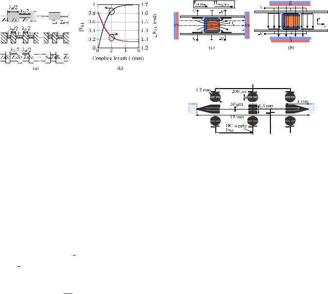
Fig. 2. (a) Half-wave stepped-impedance microstrip filter, the equivalent NRD filter’s dielectric core and the corresponding S-parameter matrix network. (b) Simulation results of the reflection coefficient versus l.
as shown at the bottom of Fig. 2(a). First, the reflection coefficient’s magnitude at each junction is calculated, according to [6]. Since lossless junctions are assumed, it is sufficient to only know one matrix element to determine the complete S-parameter matrix. Therefore, only the reflection coefficient S11 is considered. The magnitude of the reflection coefficients depends on the coupling length l and the width c of the coupling line, see Fig. 1, where c = 250 μm. Knowing the calculated reflection coefficient’s magnitude for the defined filter parameters, the corresponding coupling length l must be determined. Therefore, a full-wave simulation of the coupling line is performed for varying coupling lengths l. The required coupling length for the calculated reflection coefficient magnitude is read from the simulations results plotted in Fig. 2(b). A condition for the S-parameter matrix network is that the junction reflection coefficients must be real, therefore the phase at each junction must be either 0 or π . Hence, the simulated phase deviations, as shown in Fig. 2(b), must be compensated at every junction by
n = |
S11(ln )/2 |
(1) |
where S11(ln ) is the simulated junction phase. The physical resonator lengths, which must have an electrical length of π , are calculated according to
dn = |
λg |
( n + n+1) |
(2) |
2π |
where λg is the guide wavelength in the resonator and the phase compensations n and n+1 at each end of the resonator are reducing the physical length. For tunability, LC is filled into the resonators, in which open LC containers are milled. Therefore, the guide wavelength in the resonator is not constant and depends on the LC’s orientation to the E -field, due to the LC’s dielectric anisotropy, by which the center frequency of the filter can be tuned. The guide wavelengths for varying LC permittivities are obtained from simulations for a minimum LC container wall thickness of 200 μm at 60GHz. The center of the guide wavelength range was found at 6.65 mm, which corresponds to a relative permittivity of εr,LC = 2.75. The optimized dimensions at 60 GHz for the defined filter parameters are l1 = l4 = 2.38 mm, l2 = l3 = 4.88 mm, d1 = d3 = 1.37 mm, and d2 = 1.35 mm.
III. ELECTRIC BIASING SYSTEM
For the LC orientation, an external bias field is necessary, either electric or magnetic, since the LC molecules are aligning
45
Fig. 3. Bias schemes, overlay of magnetic and electric biasing, for (a) parallel and (b) orthogonal orientation of LC molecules in a single resonator and the corresponding positioning of the permanent magnets. For the measurements, all resonators are equally biased with one method only.
Fig. 4. Drawing of the designed mode suppressing electrode network.
along the applied bias field. For electric biasing, an electrode network is designed, where the dc bias field can be continuously adjusted from parallel to orthogonal orientation with respect to the RF field. Three pairs of electrodes are used to enable parallel and orthogonal orientation, depending on the bias scheme, as shown in Fig. 3. The curved dc field lines for parallel orientation in Fig. 3(a) are fitting with the RF E -field of the NRD’s operating LSM01 mode, shown in Fig. 1. Since the electrodes are placed inside the NRD, their influence on the propagating RF mode has to be minimized. For simple straight biasing lines, parasitic modes are excited. To avoid this, a mode suppressing electrode structure is designed, using full-wave simulations, where the optimized electrode structure is shown in Fig. 4. Both ends of the middle electrode are tapered for better matching and, furthermore, stubs are designed to avoid RF leakage from the dc supply lines. To minimize the middle electrode’s influence, the width is set to 50 μm between the resonators. For the outer electrodes, the best performance was achieved for round structures. Moreover, all electrodes are slotted for further resonance suppression. For magnetic biasing, two permanent magnets are positioned by hand, as depicted in Fig. 3.
IV. FABRICATION AND CHARACTERIZATION
For the characterization, a transition from WR15 to NRD is designed and fabricated, as shown in Fig. 5, with tapers and a horn for a smooth transition from the TE10 to the LSM01 mode. The parallel plates of the NRD and the two transitions are milled out of a single piece of brass in split-block technology. The electrodes are etched on a 12-μm-thick Pyralux polyimide laminate with 18-μm-thick single copper clad. After the containers are filled with the LC, the NRD’s split-block halves and the Rexolite slab are assembled. For the demonstrator, no sealing of the LC cavity was needed. The LC is held in position by capillary force and no leakage occurs. The measurements are performed by using a PNA-X from Keysight Technologies with the electric and magnetic biasing to verify the electrode’s performance. For electric biasing,
Authorized licensed use limited to: Cornell University Library. Downloaded on September 04,2020 at 11:17:07 UTC from IEEE Xplore. Restrictions apply.

46 |
IEEE MICROWAVE AND WIRELESS COMPONENTS LETTERS, VOL. 29, NO. 1, JANUARY 2019 |
TABLE I
COMPARISON OF TUNABLE THREE-POLE LC BANDPASS FILTERS
Fig. 5. Fabricated NRD LC BPF including the WR15 to NRD transitions. with state-of-the-art three-pole LC BPFs is given in Table I. Microstrip LC filters are realized at 30 GHz [2] and as well at 


 50 GHz as 85 GHz in [7]. They have a higher τ and lower IL,
except at 85 GHz with an IL of 7.6 dB. However, these filters
are not suitable for the channel selection, due to their FBW
larger than 10%. Waveguide LC filters at 20 GHz with equal
FBW and IL achieved a τ of 2.3%, but only with magnetic biasing [3].
V. CONCLUSION
Fig. 6. Measurement and simulation results of the BPF for orthogonal and parallel orientation of the LC. Furthermore, two intermediate states are shown, measured with electric biasing.
a voltage of ±200 V was applied to the electrode network. The measured and simulated S-parameters for parallel and orthogonal orientation of the LC are shown in Fig. 6. A detailed analysis has revealed that the difference in the center frequency shift between the initial simulation and measurement is mainly caused by manufacturing tolerances of the LC container, which has a wall thickness of 350 μm instead of 200 μm. Therefore, the LC volume is reduced, which leads to a frequency shift and less tunability. Hence, the initial simulated tunability of the center frequency of 3.7% was not achieved in the measurement with 3% and 2.5% for the magnetic and electric biasing, respectively. The cylindrical shape of the drill, where the corners inside the LC cavity are rounded, also causes a slight shift in the center frequency. Manufacturing tolerances of the coupling line lengths and thicknesses are causing a broader FBW as in the initial simulation. A second simulation of the fabricated filter has been performed, to verify the impact of the manufacturing tolerances. The results are in a very good agreement with the measurement results, as shown in Fig. 6. Furthermore, the simulated insertion losses (ILs) are matching very well with the measurement results, which are between 4.9 to 6.2 dB in the passband over the whole tuning range, including the losses of both WR15 transitions. Moreover, the desired ripple characteristics in the passband are vanished for all tuning states, due to the losses. The extracted unloaded quality factor, Qu , ranges between 100–164 and 96–141 for the magnetic and electric biasing, respectively. A comparison
This letter presents the first tunable NRD BPF based on LC technology at V -band. The three-pole Chebyshev filter was designed at 60 GHz with 1% FBW and 0.2−dB passband ripple level. For the electric biasing, a novel mode suppressing the electrode design was shown. The measurements were carried out with the magnetic and electric biasing. A tuning range of 1.75−1.5 GHz were measured, which corresponds to a tunability of 3% and 2.5% for the magnetic and electric biasing, respectively. Moreover, the ILs are in the range of 4.9–6.2 dB. The filter has an unloaded quality factor 96–41 for the electric biasing over the tuning range. The filter properties can be improved further, e.g., by applying more recent microwave LC mixtures.
ACKNOWLEDGMENT
The authors would like to thank CST AG, Darmstadt, Germany, for their support, and Merck KGaA, Darmstadt, Germany, for the supply of the liquid crystal.
REFERENCES
[1]C. Weickhmann, R. Jakoby, E. Constable, and R. A. Lewis, “Time-domain spectroscopy of novel nematic liquid crystals in the terahertz range,” in Proc. 38th Int. Conf. Infr., Millim., THz Waves (IRMMW-THz), Sep. 2013, pp. 1–2.
[2]M. Yazdanpanahi and D. Mirshekar-Syahkal, “Millimeter-wave liquid- crystal-based tunable bandpass filter,” in Proc. IEEE Radio Wireless Symp., Jan. 2012, pp. 139–142.
[3]T. Franke, A. Gaebler, A. E. Prasetiadi, and R. Jakoby, “Tunable Ka-band waveguide resonators and a small band band-pass filter based on liquid crystals,” in Proc. Eur. Microw. Conf., Oct. 2014, pp. 339–342.
[4]T. Yoneyama, F. Kuroki, and S. Nishida, “Design of nonradiative dielectric waveguide filters (short papers),” IEEE Trans. Microw. Theory Techn., vol. MTT-32, no. 12, pp. 1659–1662, Dec. 1984.
[5]C. Fritzsch and M. Wittek, “Recent developments in liquid crystals for microwave applications,” in Proc. IEEE Int. Symp. Antennas Propag. USNC/URSI Nat. Radio Sci. Meeting, Jul. 2017, pp. 1217–1218.
[6]P. Jedrzejewski and M. Mrozowski, “Design of NRD-guide bandpass filters,” in Proc. 12th Int. Conf. Microw. Radar (MIKON), vol. 1, May 1998, pp. 3–7.
[7]E. Economou et al., “Electrically tunable open-stub bandpass filters
based on nematic liquid crystals,” Phys. Rev. Appl., vol. 8, no. 6, p. 64012, Dec. 2017.
Authorized licensed use limited to: Cornell University Library. Downloaded on September 04,2020 at 11:17:07 UTC from IEEE Xplore. Restrictions apply.