

диафрагмированные волноводные фильтры / 7f113410-7862-4f76-827d-938b4879b11f
.pdf2540 |
IEEE TRANSACTIONS ON MICROWAVE THEORY AND TECHNIQUES, VOL. 63, NO. 8, AUGUST 2015 |
Efficient Design of Waveguide Manifold Multiplexers Based on Low-Order EM Distributed Models
Santiago Cogollos, Member, IEEE, Pablo Soto, Member, IEEE, Vicente E. Boria, Senior Member, IEEE, Marco Guglielmi, Fellow, IEEE, María Brumos, Member, IEEE, Benito Gimeno, Member, IEEE, and David Raboso
Abstract—In this paper, a new systematic technique to design manifold-coupled multiplexers in waveguide technology is proposed. The new technique uses generalized low-order electromagnetic (EM) distributed models, which constitute a half-way point between the fast, but imprecise, analytical models, and the more accurate, but costly, full-wave EM models. The method can be applied to contiguous and noncontiguous channel multiplexers, in both  -plane or
  -plane configurations. This paper covers the complete design procedure for manifold multiplexers, starting from the required specifications and finishing with the physical dimensions. After explaining the general design technique for multiplexers with channel filters based on transmission-line resonators, the method is specialized for the design of classic multiplexers with circular-waveguide dual-mode filters. As a further application example, the same methodology is also used for the design of a nonconventional tuningless wideband multiplexer with a new type of rectangular waveguide filters. This paper is concluded with a comparison between simulation and measurements for the wideband multiplexer. Excellent agreement between measurements and simulations are demonstrated, thereby validating the complete design procedure.
Index Terms—Design methodology, distributed parameter circuits, equivalent circuits, microwave filters, multiplexing.
I. INTRODUCTION
MULTIPLEXERS are passive devices employed to divide a wideband signal into several channels, or to combine
thesignalcomingfrom multiple channelsinto a wideband signal
Manuscript received November 20, 2014; revised April 18, 2015; accepted May 28, 2015. Date of publication June 19, 2015; date of current version August 04, 2015. This work was supported by the Ministerio de Economía y Competitividad, Spanish Government, under Research Project TEC2013-47037-C5-1-R and Research Project TEC2013-47037-C5-4-R, and by the European Space Agency (ESA) and Val Space Consortium (VSC) High Power RF Space Laboratory. This paper is an expanded version from the IEEE MTT-S International Microwave Symposium, Tampa Bay, FL, USA, June 1–6, 2014.
S. Cogollos, P. Soto, V. E. Boria, and M. Guglielmi are with the iTEAM, Departamento de Comunicaciones, Universidad Politécnica de Valencia, Valencia E-46022, Spain (e-mail: sancobo@dcom.upv.es; pabsopac@dcom.upv.es; vboria@dcom.upv.es; marco.guglielmi@iteam.upv.es).
M. Brumos was with the iTEAM, Departamento de Comunicaciones, Universidad Politécnica de Valencia, Valencia E-46022, Spain. She is now with the Thales Alenia Space, Tres Cantos, Madrid E-28760, Spain.
B. Gimeno is with the Departamento de Física Aplicada–Instituto de Ciencia de Materiales(ICMUV),Universidadde Valencia,Burjasot (Valencia) E-46100, Spain.
D. Raboso is with the Payloads Systems Division, European Space Agency, 2200-AG Noordwijk, The Netherlands.
Color versions of one or more of the figures in this paper are available online at http://ieeexplore.ieee.org.
Digital Object Identifier 10.1109/TMTT.2015.2442990
[1], [2]. They are typically composed of a certain number of filters connected together to form a complex structure. Microwave multiplexers find wide application in communication systems, such as telecommunication satellites or wireless base stations [1], [3], [4].
In communication satellites, input multiplexers are typically employed to split the signal that reaches the satellite so that each channel can be amplified separately. The signals coming from the amplifiers are then combined by an output multiplexer, for being transmitted back to the earth. Since the power level of the amplifiersislimited,itisimportanttomaintain thesystem losses as low as possible. Furthermore, passive devices located at the output stage of the satellite must be able to deal with very high power signals [5]. For these reasons, therefore, the ideal choice for satellite communication payloads [1], [2] is the waveguide technology.
Several configurations are possible for the implementation of microwave multiplexers [1], [4]. Some of them make use of hybrids or circulators, which provide a high isolation between filters, resulting in a relatively easy design and tuning process. However, these configurations also have some drawbacks. First of all, the combining elements introduce losses. Furthermore, these devices are quite bulky, which is always an issue for satel- litepayloads.Manifold-coupled multiplexers,ontheotherhand, are preferable in terms of both size and performance [6]–[8] since they use a simple common waveguide to connect all the filters. Unfortunately, the design and tuning process is complicated by the strong interaction between different channels [6], [7], [9]. In fact, to take this interactions into account, the structure must be designed as a whole, which, in turn, involves a huge number of variables to be considered at the same time.
Multiplexers have been conventionally designed using analytical models for the channel filters [7], [10]. However, these analytical models do not take into account all relevant electromagnetic effects occurring in the real structure, and normally lead to an inaccurate definition of the starting point in the electromagnetic (EM) analysis. As a result, a cumbersome and time-consuming optimization carefully supervised by a skilled designer is commonly required. In order to achieve a more realistic prototype, hybrid procedures have been introduced, where some parts of the structure are replaced with full-wave EM models [11]–[13]. Alternatively, space-mapping techniques (linking circuital models with full-wave EM simulations) have also been applied to refine each individual filter of the multiplexer [6], [14]–[16]. Some techniques have also been developed to accurately model the manifold T-junctions [17], to obtain a good starting point for the manifold dimensions in
0018-9480 © 2015 IEEE. Personal use is permitted, but republication/redistribution requires IEEE permission. See http://www.ieee.org/publications_standards/publications/rights/index.html for more information.

COGOLLOS et al.: EFFICIENT DESIGN OF WAVEGUIDE MANIFOLD MULTIPLEXERS BASED ON LOW-ORDER EM DISTRIBUTED MODELS |
2541 |
the circuit model [18], or to flexibly increase the number of channels in an already designed multiplexer [19].
In the last years, some works related to the design of multiplexers with moderate bandwidths have been reported, where complex models for the channel filters were employed, together with simple models for the manifold [20]. However, the wideband case has only been considered for filters, and not for entire multiplexers, where an increased bandwidth entails a much more complex design due to the interactions. In [21], a modified structure for the channel filters has been proposed, which is able to compensate spurious occurring in the manifold, but it also entails an increased filter size.
In [22], a new procedure to design conventional manifold multiplexers with narrow-band dual-mode filters was outlined. It exploited a distributed model of the complete multiplexer conceived for this particular geometry. This paper extends the previous idea, and provides a unifying technique valid for general multiplexers with filters based on transmission-line resonators. This generalization is accomplished by broadening the classic concept of distributed model into a multimode distributed model, thus being able to consider more accessible modes per waveguide section, including also nonpropagating modes if needed.
The proposed procedure is based on a low-order multimode distributed model of the entire multiplexer, capable of incorporating all essential high-order effects. The behavior of a distributed multimode model can be very close to the one of the real structure, provided that only the relevant EM modes of the component parts are properly included in the model. As a result, an excellent tradeoff between numerical efficiency and computational accuracy can be obtained. The proposed technique exploits the fast low-order distributed (multimode) model for carrying out a systematic design procedure with several welldefined steps, involving a limited number of design variables. When this half-way model satisfies the required specifications, it is transformed into the more precise full-waveEM model.Due to the accuracy of the low-order model, the response of the initial structure will already be very close to the desired one. As a result, only a final EM refinement will be needed to successfully complete the design task.
To prove the effectiveness of the technique, we first describe in this paper the design of classic multiplexers with dual-mode filters [20]. Furthermore, the design of a nonconventional tuningless multiplexer covering a very wide frequency range (fractional bandwidth of about 30%) is also discussed, including a comparison between computed and measured performance.
This paper is organized as follows. Section II explains the proposed design technique for general manifold-coupled multiplexers using waveguide technology. Section III applies the proposed technique to the design of classic manifold multiplexers with circular-waveguide dual-mode (CWDM) filters. Section IV deals with the design of a wideband tuningless multiplexer for measuring passive intermodulation (PIM) effects at K-band. The main conclusions are finally outlined in Section V.
II. DESIGN METHODOLOGY
In this section, we describe the general method to design a manifold-coupled multiplexer in waveguide technology making
Fig. 1. Structure of the generalized distributed model of a multiplexer. All the elements in the model must consider the waveguide dispersion.
use of generalized low-order distributed models. The design technique is very general, and can be applied to multiplexers with a wide variety of filter structures. The only requirement is that it must be possible to represent all channel filters, and all other required elements, by means of distributed models. This is indeed the case for many different types of microwave filters, which use lengths of uniform waveguides as resonators.
A. Distributed Model Choice and Initialization
A (multimode) distributed model can be defined as any model that uses transmission lines (modes) and takes into account the most relevant electromagnetic features of the real structure. Fig. 1 shows a diagram of the distributed model of a general manifold multiplexer. The T-junctions are usually simulated with a full-wave EM solver. They must be simulated only once since their dimensions will not change during the design process. The waveguide sections along the manifold, and the ones connecting the manifold with the filters, can also be simulated with an EM solver, or alternatively modeled with an equivalent circuit. The number of connecting modes used for the equivalent network representation of such elements must be suitably chosen to include all the relevant interactions. Finally, the channel filters are represented with generalized low-order distributed models adapted to each particular filter structure.
The procedure starts with the design of the distributed model of each channel filter. At this point, the filters are considered isolated, and each of them is designed to comply with the frequency specifications of the corresponding channel.
The next step is to connect the distributed model of the filters to the manifold, thereby obtaining a structure like the one shown in Fig. 1. As explained in [6], the initial spacings between  -plane or
  -plane junctions must be normally set at


 , where
  is as low as possible in order to achieve a com-
pact design and to minimize undesired resonances. The spacing
between the |
last junction and the short circuit is |
|
|
|
|
|
|
|
|
|
|
|
for |
|||||||||||||
|
-plane and |
|
|
|
|
|
|
|
for |
|
-plane. The stub lengths between the |
|||||||||||||||
|
|
|
|
|
|
|||||||||||||||||||||
filters and the T- |
|
|
|
junctions are also initialized at |
|
|
|
|
|
|
|
|
. |
|
|
|
|
|
||||||||
|
|
|
|
|
|
|
|
|
|
|
|
|
|
|
||||||||||||
B. Optimization of the Distributed Model
Even though the single filters have a compliant response in isolation, when they are put together with the manifold to form the multiplexer, their responses will change due to interactions between the different channels. Indeed, the performance of this initial multiplexer will probably be quite far from the desired one. In order to achieve a good response, an optimization over

2542 |
IEEE TRANSACTIONS ON MICROWAVE THEORY AND TECHNIQUES, VOL. 63, NO. 8, AUGUST 2015 |
the distributed model needs to be performed. The optimization process to be followed can be summarized as follows.
1)Optimize the lengths of the transmission lines placed between the T-junctions, and between the short-circuit and the last T-junction.
2)Optimize the length of the transmission lines between the T-junctions and the filters.
3)Optimize all the transmission lines together (between T-junctions and between T-junctions and filters).
4)Optimize the first three or four parameters of each filter. Fig. 2. Structure of an individual CWDM filter. The stub length connecting the filter to the manifold can
be also included. This is done with each filter separately.
The previous steps must be repeated until the desired response is reached. After the first round, more parameters may be included in the filter optimization, especially when dealing with contiguous multiplexers. After the second round, the length of the lines (manifold and stubs) change very little so that the corresponding steps can be avoided, thus focusing only on the filters. Normally, two or three rounds are enough to achieve a good response.
C. Transformation to the Full-Wave EM Model
Once the generalized distributed model of the multiplexer has been synthesized, it must be transformed into the corresponding full-wave EM model. This more precise model will take into account some features of the real structure not considered by the distributed model, such as the complete set of high-order modes generated in some parts of the physical device. Nevertheless, since the major effects have already been included in the loworder model, the initial point of the full-wave EM model will be rather good, and a slight refinement will be usually enough to achieve the required frequency response.
III. DESIGN OF MANIFOLD MULTIPLEXERS WITH
DUAL-MODE FILTERS
The general design methodology explained in Section II is going to be specialized to the design of manifold multiplexers with CWDM filters. These filters are widely used as channel filters in satellite communications due to the compact size, high unloaded quality factor, and flexibility for realizing various required cross-couplings [1], [10], [23]. As an example, the design process will be first explained with a ten-channel  -plane noncontiguous multiplexer with four-pole CWDM filters. Finally, the technique will also be used to design a contiguous eight-channel multiplexer.
A. Multiplexer With Lumped Element Models of the Filters
The structure of the CWDM filter considered is shown in Fig. 2. First, the lumped element model of each filter is designed for obtaining the desired ideal response of the corresponding channel. The lumped element model is composed of LC resonatorsandideal inverters to model the couplings (whosevalues are derived from the corresponding coupling matrix elements). The coupling matrix is synthesized as doubly terminated since the design example is noncontiguous.
Once all the lumped element models of the filters are obtained, they must be connected to the manifold. Fig. 3 shows a
Fig. 3. Multiplexer structure with the lumped model of each CWDM filter.
Fig. 4. Response of the initial multiplexer with the lumped model of the ideal CWDM filters.
simplified diagram of the multiplexer structure with the lumped element model for each filter. As it is usual, the transmission lines in the manifold are initialized considering a value of 

 so all the spacings (both between T-junctions and between T-junctions and filters) are set to

 . Since the transmission lines in the manifold are long enough to attenuate high-order EM modes, only thefundamental mode is considered for the distributed model. These waveguides are modeled with an equivalent
  -network including their distributed behavior, while the T-junctions are simulated electromagnetically and their S-pa- rameters (for the fundamental mode) are introduced in the circuit. The initial response of the resulting model of the multiplexer is shown in Fig. 4. As can be seen, its response is still quite far away from the desired one.
The next step is to perform an optimization of the previous model of the multiplexer, following the general optimization algorithm described in Section II. This step will be very fast because it is applied over a circuit model. The optimized response of the lumped element model is shown in Fig. 5.

COGOLLOS et al.: EFFICIENT DESIGN OF WAVEGUIDE MANIFOLD MULTIPLEXERS BASED ON LOW-ORDER EM DISTRIBUTED MODELS |
2543 |
Fig. 5. Response of the initial multiplexer model after optimization. The lumped element model of the channel filters has been used to represent the complete structure.
Fig. 6. Structure of the multiplexer with the distributed model of the optimized CWDM filters.
B. Multiplexer With the Distributed Model of the Filters
Next, the previously optimized lumped element model of the filters must be replaced with their distributed counterparts, thus obtaining the structure shown in Fig. 6.
Each LC lumped resonator is replaced by a transmission line (divided into two sections) of length (for 


 dual-mode filters)
(1)
where 
 is the resonant frequency and
  is the guide wavelength of the mode used to implement the resonator. Note that, since the lumped element model of each channel filter has been optimized, they are now asynchronously tuned (i.e., the resonators inside each filter resonate at different frequencies). Therefore, the length of the transmission lines will also be different. On the other hand, the inverter values can be easily obtained by using the simple expressions compiled in [24]. However, in this case, since asynchronous resonators are considered, they must be suitably modified. The new inverter values are now
(2a)
(2b)
(2c)
(2d)
(2e)
(2f)
where 
 is the corresponding inverter value in the lumped element model (after optimization), and
 is the guide-wave- length fractional bandwidth of the
  th resonator (using
 instead of
  ). In the proposed design example, the


 mode is employed. These filters can be properly represented by a distributed model including only the propagating modes, which considers one accessible mode in the input/output ports, and the two degenerate modes inside each resonant cavity.
After substituting the lumped model of the filters by their distributed models, if the channel fractional bandwidths are small (e.g., less than 1%, like in the case here considered), the response of the new distributed model of the multiplexer will be practically the same as the response of the lumped element model so no further optimization will be required. For filters with wider bandwidths, a slight optimization may be necessary.
Note that, in this case, we have chosen to optimize the multiplexer with the lumped element model of the filters, and then transform each channel to the corresponding distributed model. However, it would be equally valid to carry out the transformation from lumped to distributed models before the optimization. In any case, the key point here is to obtain a distributed model of the multiplexer complying with the specifications, which is more similar to the real structure, and therefore can be more rapidly transformed into the actual physical dimensions.
C. Extraction of Physical Dimensions
From the optimized distributed model of the entire multiplexer, the physical dimensions of the dual-mode filters can be obtained following the design process described in [24]. In this case, the cavity radius of the filters must be chosen to avoid unwanted resonances in the bandwidth of the whole multiplexer. Note also that now the response for the filters will not be symmetric.
The spacings between T-junctions, and between the last T-junction and the short circuit, are the same as the ones obtained with the distributed model of the multiplexer. The spacings between junctions and filters, on the other hand, must be changed to take into account the effect of the input iris of each filter. The loading effect introduced by the iris in the input-waveguide side must be compensated by subtracting its corresponding phase shift to the electrical length of the stub obtained in the distributed model. By considering, therefore, the stub-filter combination, both distributed model and EM model are exactly equivalent. The required formulation to calculate this phase shift is also detailed in [24].
Once all dimensions of the filters and the stubs have been computed, they can be assembled together to create the multiplexer. After that, the EM model of the multiplexer gives the

2544 |
IEEE TRANSACTIONS ON MICROWAVE THEORY AND TECHNIQUES, VOL. 63, NO. 8, AUGUST 2015 |
Fig. 7. Response of the initial EM model of the noncontiguous ten-channel |
Fig. 9. Response of the optimized EM model of an eight-channel contiguous |
multiplexer with CWDM filters. |
multiplexer with CWDM filters. |
Fig. 8. Physical structure of the finally optimized noncontiguous ten-channel multiplexer with CWDM filters.
response shown in Fig. 7. As can be seen, the initial response is quite close to the ideal one, and it can be easily optimized to achieve the desired final response. Although the optimization is made using an accurate EM model, it does not take a long time since the starting point is already very good. For verification purposes, we have made use of an available commercial solver (FEST3D [25]), even though any other full-wave EM solver capable to simulate the consideredstructures could have been used instead. The structure of the designed multiplexer can be seen in Fig. 8.
D. Design of a Contiguous Channel Multiplexer
The same technique explained previously can also be applied to design manifold multiplexers with CWDM filters with very closely allocated channels. However, some modifications are needed in order to achieve a more efficient design algorithm.
As pointed out in [6], although it is possible to design contiguous channel multiplexers starting from doubly terminated filters, a much closer starting point will be achieved if singly terminated networks are considered for the lumped element models. Once the lumped element model of the individual singly terminated filters have been synthesized, they are connected to the manifold to form the multiplexer. In this case, since the interactions between channels are stronger, due to a smaller frequency separation, it may be necessary to include
more parameters of the filters (commonly the first five or six) in the optimization of the multiplexer with their lumped element models. The rest of the process is exactly the same as it has been described for the noncontiguous case. An eight-channel contiguous multiplexer has been designed following this approach. The final optimized full-wave EM response is shown in Fig. 9.
IV. DESIGN OF A TUNINGLESS WIDEBAND MULTIPLEXER
WITH RECTANGULAR-WAVEGUIDE FILTERS
The multiplexer configuration studied in Section III is normally used for moderate bandwidths, which is indeed the typical case in satellite communications. As a result, the waveguide sections connected to the T-junctions are long, and a distributed model considering only the propagating modes is normally accurate enough.
However, as the multiplexer bandwidth increases, the problems associated with the manifold spurious gain importance. The way to minimize these problems is to maintain the manifold lengths, and also the stub lengths for connecting the filters to the manifold, as short as possible. However, if the lengths of the transmission lines connected to the T-junctions are very small, a new problem arises. The high-order EM modes generated in each step (T-junctions and input irises of the channel filters) are not totally attenuated, and interact with adjacent steps. That means that if the distributed model only considers the propagating modes, some important information is lost,whichwould lead to an inaccurate starting point when transforming the distributed model into the full-wave EM model.
A classic distributed model, as the one employed in Section III, is essentially equivalent to what is provided by a modal-based analysis tool considering only the propagating modes of the waveguide sections as accessible modes. For a broadband multiplexer, this is not good enough. However, we can extend this model by simply increasing the number of accessible modes included in the equivalent network representation. Normally, considering just very few modes, we will be able to build a low-order multimode distributed model, which represents accurately enough all the needed first-order information while maintaining low CPU computational efforts. The resulting low-order distributed multimode model will therefore be the key element to perform a fast translation from

COGOLLOS et al.: EFFICIENT DESIGN OF WAVEGUIDE MANIFOLD MULTIPLEXERS BASED ON LOW-ORDER EM DISTRIBUTED MODELS |
2545 |
Fig. 10. Layout of a HFRW channel filter used in the wideband multiplexer.
the circuit parameters providing the desired response to the physical dimensions, which is indeed the most time-consuming part of a manifold multiplexer design.
In this section, the design of a wideband manifold multiplexer is described. The final design is employed in a test bed for measuring PIM effects at the European High Power RF Space Laboratory.1 The multiplexer is composed of six noncontiguous channels. The first five channels have a bandwidth of 420 MHz and are centered at 18.10, 18.69, 19.28, 19.87, and 20.46 GHz, respectively. The sixth channel has a wider bandwidth of 1.4 GHz and is centered at 23.4 GHz. The relative bandwidth of the multiplexer is, therefore, about 30%. In addition, the hardware must be tuningless for avoiding PIM, and provide a return loss greater than 20 dB.
A. Geometrical Description of the Multiplexer
In order to design a tuningless multiplexer it is essential to conceive a geometrical configuration, which can be accurately simulated. Otherwise, the design inaccuracies combined with typical manufacturing tolerances will not allow to meet the specifications. For this particular multiplexer, we looked for a constant-width structure composed of simple elements. This type of structures can exploit the speed and extremely high accuracy of 2-D modal analysis tools.
For channels 1–5, it was decided to use a recently presented configuration of waveguide filters, which are called hybrid folded rectangular waveguide (HFRW) filters [26]. In addition to being a constant width and easy to simulate, this new configuration is also low PIM, quite compact, and allows fot the inclusion of transmission zeros. In this multiplexer, four-pole HFRW filters with 


 -mode resonators and two transmission zeros have been considered (see Fig. 10). With a proper placement of the capacitive windows between vertically stacked resonators, a part of the


 resonator also behaves as a short-circuited stub providing a transmission zero at the desired frequency. In contrast to extracted-pole filters, the regions of the structure implementing the transmission zeros are included in the resonant nodes, and therefore do not require additional space.
The last channel was implemented using a fifth-order inline rectangular waveguide filter with capacitive irises. The manifold sections and the stubs connecting the filters to the manifold have also the same width of the individual filters.
During the design procedure of the low-order distributed model, some spikes appeared in the band of the last filter centered at 23.4 GHz. They were related to strong interferences
1European Space Agency (ESA) and Val Space Consortium (VSC) High Power RF Space Laboratory. [Online]. Available: http://www.val-space.com
with channel 1 and 2 filters. The use of 


 resonators to shift such interactions to higher frequencies was not possible due to an unacceptable twofold increase in sensitivity to manufacturing tolerances. Instead, the width of some regions of such filters were increased to achieve such a goal. Although the resulting structure was not uniform in width anymore, it could still be decomposed in constant-width blocks easily amenable to accurate EM analysis.
B. Design of the Low-Order EM Distributed Model
The first step is to design the low-order EM distributed model of the six individual channel filters. The design procedure for filters 1–5 can be found in [26]. Once the isolated filters have been designed, they must be connected to the manifold. The initial multiplexer structure is similar to the one depicted in Fig. 1, but considering a low-order EM distributed model of all the elements (T-junctions, waveguides, and filters). We have used the FEST3D [25] modal analysis tool to perform the optimization, with a maximum number of five accessible modes (and the remaining modal parameters reduced accordingly), to ensure an adequate precision while allowing fast simulations.
In order to avoid unwanted resonances, the length of the interconnecting waveguide sections must be kept small. Following [9], a direct connection (i.e., without using stubs) of the filters to the manifold was first attempted. However, a pair of resonances appeared around the last channel, which could not be moved simultaneously out of the band of interest. Some waveguide sections connecting adjacent T-junctions were too long, and they could not be shortened due to the reduction of the degrees of freedom related to the lack of stubs.
The use of stubs for connecting the filters can therefore be advantageous for the manifold design. However, the stubs must be very short to avoid unwanted effects (corresponding to a rapid variation with frequency of the channel impedance observed from the manifold). As a result, the transmission lines between the T-junctions, between the last T-junction and the short circuit, and between the T-junctions and the filters were all initialized to a value of 2 mm. This is an appropriate choice for being short to limit spurious spikes, for being close to a suggested starting point of 


 (
(

 ), and for allowing at the same time a certain optimization capacity towards both upper and lower values. The initial response of the low-order EM distributed model of the multiplexer is shown in Fig. 11. As it happened in the previous examples, although the response of the isolated filters comply with the specifications, interactions between channels cause a severe degradation in the global response. Note also the spurious resonance at about 24.5 GHz placed just outside of the multiplexer band.
The initial low-order multimode model was optimized following the procedure explained in Section II. Due to the high computational efficiency of the low-order distributed model, this step was successfully completed in a short time. After the optimization, the multiplexer has the response shown in Fig. 12. The ripple lobes, which resulted to be more sensitive in a tolerance analysis, were designed with lower return-loss levels, in order to ensure a properly manufactured multiplexer. This is the

2546 |
IEEE TRANSACTIONS ON MICROWAVE THEORY AND TECHNIQUES, VOL. 63, NO. 8, AUGUST 2015 |
Fig. 11. Response of the initial low-order EM distributed model of the wideband multiplexer.
Fig. 12. Response of the low-order EM distributed model of the wideband multiplexer after the optimization process.
reason why, as it can be appreciated in Fig. 12, the return-loss level of the filters is not homogeneous.
C. Transformation to the Full-Wave EM Model
Once the low-order EM distributed model provides an adequate response, the number of EM modes in the structure is significantly increased in order to guarantee an accurate full-wave simulation of the real multiplexer. Following a similar procedure to the one carried out for multiplexers with CWDM filters (see Section III-C), the optimized low-order model is exploited to obtain improved initial dimensions of the full-wave EM model.
1)The design variable governing each coupling element is adjusted to provide the same coupling coefficient obtained in the optimized low-order model (i.e., with a reduced number of modes) at the central frequency of the corresponding filter.
2)The differences between both models in the input phase of the first coupling element of each filter are used to readjust the length of the interconnecting stubs to the manifold, as already described in Section III-C.
3)The design variable controlling each filter cavity is tuned to match the resonant frequency of the same cavity from the low-order model by using the group-delay method [24]. It is important to terminate the resonant cavity with the new input and output coupling elements derived in 1) to properly take into account the loading effect.
Fig. 13. Response of the initial full-wave EM model of the wideband multiplexer.
Fig. 14. Structure of the designed PIM test bed with the wideband six-channel manifold multiplexer and a high-pass filter connected to the sixth channel filter.
The remaining dimensions are kept unchanged, including the length of the stubs controlling the transmission zeros of the channel filters (since the shift in the frequency position of the transmission zeros between both models was negligible).
After applying this procedure, which allows us to go from the low-order to the full-wave EM model without resorting to models with intermediate accuracy, the response shown in Fig. 13 is obtained.
One of the advantages of low-order distributed models is the flexibility of choosing a suitable tradeoff between model accuracy and simulation time for a particular structure. In our case, we found that a low-order distributed model with up to five accessible modes provides a fair level of accuracy and is also very fast. As a result, the deterioration of the response shown in Fig. 13 is not very important. However, the simulation time of the full-wave EM model was more than 100 times higher than the low-order distributed model. This proves that, with a proper choice of the number of modes in the low-order distributed model, all the relevant information can be included without paying the cost of very expensive simulations.
COGOLLOS et al.: EFFICIENT DESIGN OF WAVEGUIDE MANIFOLD MULTIPLEXERS BASED ON LOW-ORDER EM DISTRIBUTED MODELS |
2547 |
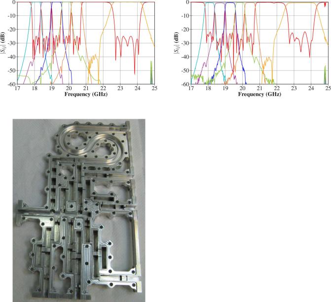
Fig. 15. Response of the optimized full-wave EM model of the wideband multiplexer with a high-pass filter connected to the sixth channel filter.
Fig. 17. Measured response of the wideband multiplexer with a high-pass waveguide filter connected to the sixth channel filter.
Fig. 16. Manufactured PIM test bed with the wideband six-channel manifold multiplexer.
The final step is to perform a last optimization of the fullwave EM model. Due to the excellent point already obtained (see Fig. 13), the multiplexer design is almost done, and different type of strategies can be successfully applied to complete the design. However, due to the geometrical properties of the structure already discussed in Section IV-A, we opted to carry out this optimization acting directly on each filter sequentially and then perform a final refinement of all the filters simultaneously. The optimization of the full-wave EM model was, in any case, quite fast, as the number ofrequired EM analysis iterations was low.
A high-pass filter, which consists of a simple bent rectangular waveguide section with reduced width, was also connected to the sixth channel filter. The final structure is shown in Fig. 14. It can be observed that some of the channel filters have been bent to reduce the overall size and the layout of the component, and simultaneously allow a proper arrangement of the channel
filters, providing enough separation for thermal performance. The final full-wave EM response of the optimized structure can be seen in Fig. 15.
D. Fabrication and Measurements
The wide band multiplexer was then manufactured (see Fig. 16). The measured response is shown in Fig. 17. As can be appreciated, the final response fulfills the specifications and is very close to the simulated one. The return loss was higher than 21.6 dB for all channel filters, and the frequency shift was only about 10 MHz without making use of any tuning element. These differences can be attributed to manufacturing tolerances. The insertion losses of the input channels were between 0.4 and 0.6 dB at the central frequency of the filters, which agrees with the expected attenuation for a component manufactured on bare aluminum. The component is currently being used for several test applications.
V. CONCLUSION
A new design procedure for waveguide manifold-cou- pled multiplexers has been presented, where low-order EM distributed models of the different parts of the structure are employed. A generalized multimode distributed model can, in fact, be built to include all major EM interaction effects of a particular structure, providing a good tradeoff between efficiency and accuracy. This procedure moves most of the computational work towards the fast distributed model, and provides an excellent starting point for the full-wave EM model in a very short time. From this starting point, the design can be successfully completed after a straightforward optimization process.
The proposed design technique can be applied to both contiguous and noncontiguous multiplexers, covering not only the classic narrowband case, but also nonconventional wideband configurations. The only requirement is that it must be possible to represent the channel filters by generalized multimode distributed models, which means that the resonators must be composed of lengths of uniform waveguides.
The full design process has been thoroughly explained, starting from the multiplexer specifications and ending with the extraction of the physical dimensions. The procedure has been specialized for multiplexers with CWDM filters, providing design examples corresponding to two multiplexers with ten

2548 |
IEEE TRANSACTIONS ON MICROWAVE THEORY AND TECHNIQUES, VOL. 63, NO. 8, AUGUST 2015 |
noncontiguous channels and eight contiguous channels, respectively. In both cases, very good results were obtained with a modest computational effort.
Following the same methodology, a wideband multiplexer with six rectangular waveguide channel filters was also designed. It was required a tuningless design to avoid high power issues. Therefore, a very accurate design was needed. In this case, since short manifold transmission lines were employed in order to minimize the spurious in the whole multiplexer bandwidth, it was necessary to include nonpropagating EM modes in the distributed model. The starting point of the full-wave EM model obtained was very close to the desired one so that only a small final refinement was required. The designed multiplexer was manufactured and measured, obtaining a response very close to the simulated one, thereby validating the proposed design procedure.
ACKNOWLEDGMENT
Special thanks are given to D. Smacchia, VSC, for his help with the measurements of the six-channel manifold multiplexer.
The authors would like to thank the European Space Agency (ESA) and Val Space Consortium (VSC) High Power RF Space Laboratory (A laboratory funded by the European Regional Development Fund, A way of making Europe) for financing the manufacture and experimental validation of the wideband sixchannel PIM test bed.
REFERENCES
[1]R. Cameron, C. Kudsia, and R. Mansour, Microwave Filters for Communication Systems: Fundamentals, Design and Applications. New York, NY, USA: Wiley, 2007.
[2]C. Kudsia, R. Cameron, and W.-C. Tang, “Innovations in microwave filters and multiplexing networks for communications satellite systems,” IEEE Trans. Microw. Theory Techn., vol. 40, no. 6, pp. 1133–1149, Jun. 1992.
[3]G. Macchiarella, “Synthesis of star-junction multiplexers,” IEEE Microw. Mag., vol. 12, no. 6, pp. 101–109, Oct. 2011.
[4]C.Kudsia,J. Dorey, J. Heierli, K.R. Ainsworth, andG.J.P.Lo,“A new type of low loss l4 GHz high power combining network for satellite earth terminals,” in 9th Eur. Microw. Conf., Sep. 1979, pp. 386–391.
[5]S. Lundquist, M. Mississian, M. Yu, and D. Smith, “Application of high power output multiplexers for communications satellites,” in
Proc. 18th AIAA Int. Commun. Satellite Syst. Conf. Exhibit, 2000, pp. 359–368.
[6]R. J. Cameron and M. Yu, “Design of manifold-coupled multiplexers,” IEEE Microw. Mag., vol. 8, no. 5, pp. 46–59, Oct. 2007.
[7]A. Atia, “Computer-aided design of waveguide multiplexer,” IEEE Trans. Microw. Theory Techn., vol. MTT-22, no. 3, pp. 332–336, Mar. 1974.
[8]C. Kudsia, K. Ainsworth, and M. O’Donovan, “Microwave filters and multiplexing networks for communication satellites in the 1980S,” in
Proc. AIAA 8th Commun. Satellite Syst. Conf., Apr. 1980, pp. 290–301.
[9]J. Rhodes and R. Levy, “Design of general manifold multiplexers,”
IEEE Trans. Microw. Theory Techn., vol. MTT-27, no. 2, pp. 111–123, Feb. 1979.
[10]A. Atia and A. Williams, “Narrow-bandpass waveguide filters,” IEEE Trans. Microw. Theory Techn., vol. MTT-20, no. 4, pp. 258–265, Apr. 1972.
[11]L. Accatino and M. Mongiardo, “Hybrid circuit-full-wave com- puter-aided design of a manifold multiplexers without tuning elements,” IEEE Trans. Microw. Theory Techn., vol. 50, no. 9, pp. 2044–2047, Sep. 2002.
[12]Y. Wang, S. Li, and M. Yu, “Hybrid models for effective design and optimization of large-scale multiplexing networks,” IEEE Trans. Microw. Theory Techn., vol. 61, no. 5, pp. 1839–1849, May 2013.
[13]D. Bariant et al., “Method of spurious mode compensation applied to manifold multiplexer design,” in IEEE MTT-S Int. Microw. Symp. Dig., Jun. 2002, vol. 3, pp. 1461–1464.
[14]M. Ismail, D. Smith, A. Panariello, Y. Wang, and M. Yu, “EM-based design of large-scale dielectric-resonator filters and multiplexers by space mapping,” IEEE Trans. Microw. Theory Techn., vol. 52, no. 1, pp. 386–392, Jan. 2004.
[15]M. Yu and Y. Wang, “Synthesis and beyond,” IEEE Microw. Mag., vol. 12, no. 6, pp. 62–76, Oct. 2011.
[16]M. Ismail, Y. Wang, and M. Yu, “Advanced design and optimization of large scale microwave devices,” in IEEE MTT-S Int. Microw. Symp. Dig., Jun. 2012, pp. 1–3.
[17]X.-P. Liang, K. Zaki, and A. Atia, “A rigorous three plane mode-matching technique for characterizing waveguide T-junctions, and its application in multiplexer design,” IEEE Trans. Microw. Theory Techn., vol. 39, no. 12, pp. 2138–2147, Dec. 1991.
[18]A. Morini, T. Rozzi, and M. Morelli, “New formulae for the initial design in the optimization of T-junction manifold multiplexers,” in IEEE MTT-S Int. Microw. Symp. Dig., Jun. 1997, vol. 2, pp. 1025–1028.
[19]X.-P. Liang, K. Zaki, and A. Atia, “Channel expansion and tolerance analysis of waveguide manifold multiplexers,” IEEE Trans. Microw. Theory Techn., vol. 40, no. 7, pp. 1591–1594, Jul. 1992.
[20]H. Hu and K.-L. Wu, “A deterministic EM design technique for general waveguide dual-mode bandpass filters,” IEEE Trans. Microw. Theory Techn., vol. 61, no. 2, pp. 800–807, Feb. 2013.
[21]H. Hu, K.-L. Wu, and R. Cameron, “Stepped circular waveguide dualmode filters for broadband contiguous multiplexers,” IEEE Trans. Microw. Theory Techn., vol. 61, no. 1, pp. 139–145, Jan. 2013.
[22]M. Brumos, S. Cogollos, M. Martínez, P. Soto, V. E. Boria, and M. Guglielmi, “Design of waveguide manifold multiplexers with dualmode filters using distributed models,” in IEEE MTT-S Int. Microw. Symp. Dig., Jun. 2014, pp. 1–4.
[23]A. Atia and A. Williams, “New types of waveguide bandpass filters for satellite transponders,” Comsat Tech. Rev., vol. 1, pp. 21–43, Fall, 1971.
[24]S. Cogollos et al., “A systematic design procedure of classical dualmode circularwaveguide filters usinganequivalent distributedmodel,”
IEEE Trans. Microw. Theory Techn., vol. 60, no. 4, pp. 1006–1017, Apr. 2012.
[25]FEST3D 6.8.5. Aurora Softw. Testing S.L. (on behalf of ESA/ESTEC), Valencia, Spain, 2014. [Online]. Available: www.fest3d.com
[26]S. Cogollos, P. Soto, M. Brumos, V. E. Boria, and M. Guglielmi, “Novel rectangular waveguide structures for advanced filter characteristics,” in IEEE MTT-S Int. Microw. Symp. Dig., Jun. 2014, pp. 1–4.
Santiago Cogollos (M’07) received the Telecommunication Engineering degree and Ph.D. degree from the Universidad Politécnica de Valencia, Valencia, Spain, in 1996 and 2002, respectively.
In 2000, he joined the Communications Department, Universidad Politécnica de Valencia, where, from 2000 to 2001, he was an Assistant Lecturer, from 2001 to 2002, a Lecturer, and since 2002, an Associate Professor. He has collaborated with the European Space Research and Technology Centre, European Space Agency, in the development of
modal analysis tools for payload systems in satellites. In 2005, he held a post-doctoral research position with the University of Waterloo, Waterloo, ON, Canada, where he was involved in the area of new synthesis techniques in filter design. His current research interests include applied electromagnetics, mathematical methods for electromagnetic theory, analytical and numerical methods for the analysis of waveguide structures, and design of waveguide components for space applications.
Pablo Soto (S’01–M’06) was born in Cartagena, Spain, in 1975. He received the M.S. degree and Ph.D. degree (cum laude) in telecommunication engineering from the Universidad Politecnica de Valencia, Valencia, Spain, in 1999 and 2012, respectively.
In 2000, he joined the Departamento de Comunicaciones, Universidad Politecnica de Valencia, where he has been an Associate Professor since 2012. For five months in 2000, he was a European Union (EU) Research Fellow with the European Space Research

COGOLLOS et al.: EFFICIENT DESIGN OF WAVEGUIDE MANIFOLD MULTIPLEXERS BASED ON LOW-ORDER EM DISTRIBUTED MODELS |
2549 |
and Technology Centre (ESTEC-ESA), Noordwijk, The Netherlands. His research interests comprise numerical methods for the analysis, synthesis, and fully automated design of passive components in waveguide and planar technologies, as well as the development and design of novel hardware for satellite applications.
Dr. Soto is a reviewer for the IEEE TRANSACTIONS ON MICROWAVE THEORY
AND TECHNIQUES and IEEE MICROWAVE AND WIRELESS COMPONENT
LETTERS. He was the recipient of the 2000 and 2012 COIT/AEIT National Award for the best Master thesis and Ph.D. thesis in basic information and communication technologies, respectively. He was also the recipient of the 2013 Gheorghe Cartianu Award of the Romanian Academy.
Vicente E. Boria (S’91–A’99–SM’02) was born in Valencia, Spain, on May 18, 1970. He received the Ingeniero de Telecomunicación degree (with first-class honors) and the Doctor Ingeniero de Telecomunicación degree from the Universidad Politécnica de Valencia, Valencia, Spain, in 1993 and 1997, respectively.
In 1993 he joined the Departamento de Comunicaciones, Universidad Politécnica de Valencia, where he has been a Full Professor since 2003. In 1995 and 1996, he held a a Spanish trainee position with the
European Space Research and Technology Centre, European Space Agency (ESTEC-ESA), Noordwijk, The Netherlands, during which time he was involved in the area of electromagnetic (EM) analysis and design of passive waveguide devices. He has authored or coauthored 7 chapters in technical textbooks, 75 papers in refereed international technical journals, and over 150 papers in international conference proceedings. His current research interests are focused on the analysis and automated design of passive components, left-handed and periodic structures, as well as on the simulation and measurement of power effects in passive waveguide systems.
Dr. Boria has been a member of the IEEE Microwave Theory and Techniques Society (IEEE MTT-S) and the IEEE Antennas and Propagation Society (IEEE AP-S) since 1992. He is member of the Editorial Boards
of the IEEE TRANSACTIONS ON MICROWAVE THEORY AND TECHNIQUES, IEEE MICROWAVE AND WIRELESS COMPONENTS LETTERS, Proceeding of the IET (Microwaves, Antennas and Propagation), IET Electronics Letters, and Radio Science. Since 2013, he has served as an associate editor for IEEE MICROWAVE AND WIRELESS COMPONENTS LETTERS. He is a member of the Technical Committees of the IEEE Microwave Theory and Techniques Society (IEEE MTT-S) International Microwave Symposium (IMS) and the European Microwave Conference.
Marco Guglielmi (S’79–M’81–SM’97–F’13) was born in Rome, Italy, on December 17, 1954. He received the Laurea in Ingegneria Elettronica degree from the University of Rome “La Sapienza,” Rome, Italy, in 1979. He also attended the Scuola di Specializzazione in Elettromagnetismo Applicato, University of Rome “La Sapienza,” in 1980. He received the M.S. degree in electrical engineering from the University of Bridgeport, Bridgeport, CT, USA, in 1982, and the Ph.D. degree in electrophysics from the Polytechnic University, Brooklyn, NY,
USA, in 1986.
From 1984 to 1986, he was Academic Associate with the Polytechnic University. From 1986 to 1988, he was Assistant Professor with Polytechnic University. From 1988 to 1989, he was Assistant Professor with the New Jersey Institute of Technology (NJIT), Newark, NJ, USA. In 1989, he joined the European Space Agency (ESA), as a Senior Microwave Engineer with the RF System Division, European Space Research and Technology Centre (ESTEC), Noordwijk, The Netherlands, where he was in charge of the development of microwave filters and electromagnetic simulation tools. In 2001, he was appointed Head of the Technology Strategy Section, ESTEC, where he contributed to the devel-
opment of management processes and tools for the formulation of a European strategy for space technology research and development. In December 2014, he retired from the ESA. He is currently an Invited Senior Researcher with the Polytechnic University of Valencia, Valencia, Spain, where he is involved in teaching technology innovation and strategy and performs research in applied electromagnetics and microwaves.
Dr. Guglielmi was the recipient of a Fulbright Scholarship and a Halsey International Scholarship from the University of Bridgeport, in 1981.
María Brumos (S’09–M’10) was born in Teruel, Spain, on February 17, 1986. She received the Telecommunication Engineering degree Ph.D. degree from the Universidad Politécnica de Valencia, Valencia, Spain, in 2009 and 2014, respectively. Her thesis was focused on the design of waveguide filters and multiplexers for satellite communications.
In 2015, she joined Thales Alenia Space, Tres Cantos, Madrid, Spain, where she has been involved with the design of passive microwave components for space applications.
Benito Gimeno (M’01) was born in Valencia, Spain, on January 29, 1964. He received the Licenciado degree in physics and Ph.D. degree from the Universidad de Valencia, Valencia, Spain, in 1987 and 1992, respectively.
From 1987 to 1990, he was a Fellow with the Universidad de Valencia. Since 1990, he has been as Assistant Professor with the Departamento de Física Aplicada y Electromagnetismo and Instituto de Ciencia de Materiales (ICMUV), Universidad de Valencia, where he became an Associate Professor
in 1997 and Full Professor in 2010. During 1994 and 1995, he was a Research Fellow with the European Space Research and Technology Centre, European Space Agency (ESA/ESTEC). In 2003, he spent a short stay with the Universita degli Studi di Pavia, Pavia, Italy, as a Visiting Scientific. His current research interests include the areas of computer-aided techniques for analysis of microwave and millimeter-wave passive components for space applications, waveguides and cavities structures including dielectric objects, electromagnetic bandgap structures, frequency-selective surfaces, and nonlinear phenomena appearing in power microwave subsystems and particle accelerators (multipactor effect, corona effect, and passive intermodulation phenomena).
Dr. Gimeno was the recipient of a fellowship from the Spanish Government in 2003.
David Raboso was born in Alcazar de San Juan (Ciudad Real), Spain, in 1967. He studied physics at the Autonomous University of Madrid, Madrid, Spain. He received the Masters degree in rocket science from the University of Delft, Delft, The Netherlands, in 2002.
In 1992, he joined the Payloads Systems Division, European Space Agency (ESA), Noordwijk, The Netherlands, where he became responsible for all activities related to RF breakdown in space microwave components. His participation in space programs is
extensive, beginning with pioneer observation satellites to modern interplanetary missions such as Mercury (Bepi-Colombo) or navigation constellations (Galileo). In June 2010, after 18 years in Holland, he was assigned to direct the joint ESA–VSC Laboratories RF and Space Materials, Valencia, Spain. Since 2010, he has been responsible for updating the standards related to issues of RF breakdown and passive intermodulation. He has coauthored over 100 papers in prestigious journals and scientific conferences. He co-invented nine patents.
Mr. Raboso has been the chairman of Mulcopim (the international conference covering issues of RF breakdown and passive intermodulation) since 2010.