

диафрагмированные волноводные фильтры / 9d691ff5-3602-4178-b7c7-511bdcf86d32
.pdfIEEE ANTENNAS AND WIRELESS PROPAGATION LETTERS, VOL. 6, 2007 |
285 |
Fully Integrated Passive Front-End Solutions for a V-band LTCC Wireless System
Jong-Hoon Lee, Student Member, IEEE, Nobutaka Kidera, Stephane Pinel, Member, IEEE, Joy Laskar, Fellow, IEEE, and Manos M. Tentzeris, Senior Member, IEEE
Abstract—A novel topology implementing a 3-D fully integrated filter and antenna function is proposed as a system-on-package (SOP) compact front-end solution for the low-temperature cofired ceramic (LTCC) based V-band modules. A 4-pole quasi-elliptic bandpass filter composed of four open loop resonators has been developed. It exhibits an insertion loss  3.5 dB, a return loss
  15 dB over the pass band (
 3.4 GHz) and a 3 dB bandwidth of about 5.46% (
 3.4 GHz) at the center frequency of 62.3 GHz. In addition, a series fed 1
  4 linear antenna array of four microstrip patches exhibiting high gain and fan-beam radiation pattern has been designed. Its 10 dB bandwidth is experimentally validated to be 55.4–66.8 GHz (
 18.5%). The above proposed designs have been combined together, leading to the complete integration of passives with a high level of selectivity over the band of interest. The excellent overall performance of the integrated solution is verified through a 10-dB bandwidth of 4.8 GHz (59.2–64 GHz) and a return loss
  10.5 dB over the passband.
Index Terms—Front-end module, integrated passives, low-tem- perature cofired ceramic (LTCC), millimeter-wave (mm-wave), patch antenna, quasi-elliptic filters, system-on-package (SOP), V-band.
I. INTRODUCTION
HE millimeter-wave (mm-W) front-end module is the Tfoundation of 60-GHz (V-band) wireless systems for short-range multimedia applications, such as high-speed internet access, video streaming, and content download. Its integration poses stringent challenges in terms of high performance, large number of embedded passive components, low power consumption and compactness. To overcome these major challenges, a high level of integration of embedded passive functions using low-cost and high-performance materials that can be laminated in three-dimensional (3–D), such as the multilayer low-temperature cofired ceramic (LTCC) [1] is significantly critical in the module-level design. The optimal integration of RF passives into 60-GHz (V-band) front-end module is significantly difficult since the electrical performance can be degraded by severe parasitic and interconnection losses. The microwave structures for an integrated filter and antenna function, which is commonly called a filtering antenna have
Manuscript received July 27, 2006; revised January 12, 2007. This work was supported in part by the Science Foundation (NSF) by CAREER Award #ECS9984761 and Grant #ECS-0313951, by the Georgia Electronic Design Center, and by the Georgia Institute of Technology Packaging Research.
J.-H. Lee, S. Pinel, J. Laskar, and M. M. Tentzeris are with the School of Electrical and Computer Engineering, the Georgia Institute of Technology, Atlanta, GA 30332 USA (e-mail: jonglee@ece.gatech.edu).
N. Kidera is with Asahi Glass Co., Kanagana 211-8755 Japan.
Color versions of one or more figures are available at http://ieeexplore. ieee.org
Digital Object Identifier 10.1109/LAWP.2007.891964
been implemented using stacked cavities coupled by a metallic iris at K-band [2], an electromagnetic horn [3] and a leaky waveguide [4] at X-band. Despite their large size and their implementation in low frequencies, these topologies show that the integrated filter and antenna functions have a great potential to be integrated into higher-frequency-bands modules and play a critical role for the module miniaturization if implemented in compact topologies.
In this letter, we present compact and high-performance passive building blocks and their integration, enabling a complete passives integration solution for 3-D low-cost wireless V-band front-end modules. Specifically, we discuss the development of a 4-pole cross-coupled quasi-elliptic filter, targeting high selectivity and compactness and focus on the design of a high-gain and directive series fed 1  4 linear array antenna of four microstrip patches covering 59–64 GHz. The complete integration of the above developed filter and antenna was successfully implemented with a planar transition. The integrated front-end demonstrates the excellent band selectivity through a 10-dB bandwidth (BW) of approximately 4.8 GHz (59.2–64 GHz) and return loss
  10.5 dB over the passband.
II. QUASI-ELLIPTIC FILTER
Numerous researchers [5], [6] have demonstrated narrow BW filters employing open-loop resonators for current mobile communication services at L and S bands. In this section, the design of a 4-pole quasi-elliptic filter is presented as a filter solution for LTCC 60 GHz front-end module because it exhibits a superior skirt selectivity by providing one pair of transmission zeros at finite frequencies, enabling a performance between that of the Chebyshev and elliptical-function filters [5]. The very
mature multilayer fabrication capabilities of LTCC ( |
, |
||
, metal layer |
thickness: |
9 , number |
of |
layers: 6, dielectric layer thickness: 53 |
, minimum metal |
||
line width and spacing: up to 75 |
) make it one of the leading |
||
competitive solutions to meet mm-W design requirements in terms of physical dimensions [5] of the open-loop resonators 


 , achieving a significant miniaturization because of relatively high
 , and spacing


 between adjacent resonators that determine the coupling coefficient of the filter function. All designs have been simulated using the MOM-based, 2.5 full-wave solver IE3D. Fig. 1(a), (b) shows the top and cross-section views of the microstrip quasi-el- liptic bandpass filter, respectively. The filter was designed according to the filter synthesis proposed by Hong [5] to meet the following specifications: (1) center frequency: 62 GHz (2) fractional BW: 5.61% (
 3.5 GHz) (3) insertion loss:
  3 dB
3 dB
(4) 35 dB rejection BW: 7.4 GHz. Its effective length [RL in
1536-1225/$25.00 © 2007 IEEE

286 |
IEEE ANTENNAS AND WIRELESS PROPAGATION LETTERS, VOL. 6, 2007 |
Fig. 2. The comparison between measured and simulated S-parameters (S21 and S11) of the 4-pole quasi-elliptic bandpass filter composed of open-loop resonators.
Fig. 1. (a) Top view and (b) cross-section view of 4-pole quasi-elliptic bandpass filter consisting of open-loop resonators fabricated on LTCC. All dimensions indicated in (a) are in mm.
Fig. 1(a)] and width [RW in Fig. 1(a)] has been optimized to be approximately 


 using a full-wave simulator (IE3D) [5]. The design parameters such as the coupling coefficients (

 ,
, 

 ,
, 
 ,
, 

 ) and the external quality factor


 can be theoretically calculated based on the element values of a 4-pole low-pass prototype [5]. Then, the physical spacing between resonators was extracted from full-wave simulations (IE3D) based on the theoretical values of coupling coefficients and external quality factors [5]. The quasi-elliptic filter was fabricated on the first metallization layer [metal 1 in Fig. 1(b)], which is placed two substrate layers


 above the first ground plane on metal 3. That is the minimum substrate height to realize the 50
  microstrip feeding structure on LTCC substrate. This ground plane is connected to the second ground plane located on the back side of the substrate through shorting vias (pitch: 390
 , diameter: 130
 ) as shown in Fig. 1(b) [8]. The four additional substrate layers [substrate 3–6 in Fig. 1(b)] are reserved for an integrated filter and antenna functions implementation, because antenna BW requires higher substrate thickness than the filter. Fig. 2 shows the comparison between the simulated and measured S parameters of the bandpass filer. The filter exhibits an insertion loss
  3.5 dB which is higher than the simulated values of
  1.4 dB and a return loss
 15 dB compared to a simulated value of
  21.9 dB over the passpand. The loss discrepancy can be attributed to conductor loss caused by the strip edge profile and the quality of the edge definition of metal traces since the simulations assume a perfect definition of metal strips. Also, the metallization surface
Fig. 3. (a) Top view and (b) cross-section view of a series fed 1 2 4 linear array of four microstrip patches. All dimensions indicated in (a) are in mm.
roughness may influence the ohmic loss because the skin depth in a metal conductor is very low at these high frequencies. The measurement shows a slightly decreased 3-dB fractional BW of 5.46% ( 3.4 GHz) at a center frequency of 62.3 GHz. The simulated results give a 3 dB BW of 5.61% (
 3.5 GHz) at a center frequency 62.35 GHz. The transmission zeros are observed within less than 5 GHz away from the cut-off frequency of the passband. The discrepancy of the zero positions between the measurement and the simulation can be attributed to the fabrication tolerance. However, the overall response of the measurement correlates very well with the simulation.
III. SERIES FED ARRAY ANTENNA
A series fed 1  4 linear array antenna of four microstrip patches [7] covering the 59–64 GHz band, which has been allocated world wide for dense wireless local communications [9], has been designed on LTCC substrate and its top and cross-section views are illustrated in Fig. 3(a) and (b), accordingly. The proposed antenna employs a series feed instead of a corporate feed because of its easy-to-design feeding network and low level of radiation from the feed line [7]. The matching
LEE et al.: FRONT-END SOLUTIONS FOR A V-BAND LTCC WIRELESS SYSTEM |
287 |
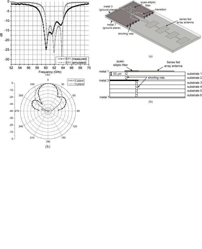
Fig. 5. (a) The 3-D overview and (b) cross-section view of the integrated filter and antenna functions.
Fig. 4. (a) Measured and simulated return loss (S11) (b) radiation patterns at 61.5 GHz of the series fed 1 2 4 array antenna.
between neighboring elements is achieved by controlling the width [PW in Fig. 3(a)] of the patch elements. The antenna was screen-printed on the top metal layer (metal 1 in Fig. 3(b)), and uses six substrate layers to provide the required broadband matching property and high gain. The targeted operation frequency was 61.5 GHz. First, the single patch resonator 


 resonating at 61.5 GHz is designed. The width-to-line ratio of the patch is determined to obtain the impedance matching and the desired resonant frequency. In our case, identical four patch resonators are linearly cascaded using thin microstrip lines [


 in Fig. 3(a)] to maximize the performance at the center frequency of 61.5 GHz. The distance [g in Fig. 3(a)] between patch elements is the critical design parameter to achieve equal amplitude and cophase (equal phase) excitation and control the tilt of the maximum beam direction. It was optimized to be 0.780 mm (


 ) for 0
 tilted fan beam antenna. Its physical length was determined to be 1.108 mm [
 in Fig. 3(a)]. Fig. 4(a) shows very good correlation between the measured and simulated return loss (S11) versus frequency for the design. The measured 10-dB BW is 55.4–66.8 GHz (
 18.5%) compared to the simulated which is 54–68.4 GHz (
 23.4%). The narrower BW might be due to the band limiting effect from the CPW measurement pad
Fig. 6. The comparison between measured and simulated return loss (S11) of the integrated filter and antenna functions.


 . Fig. 4(b) presents E-plane and H-plane radiation patterns at the center frequency of 61.5 GHz. We can easily observe the 0
 beam tilt from the radiation characteristics. The maximum gain of this antenna is 12.6 dBi.
IV. INTEGRATION
In the 60-GHz front-end module development, the compact and efficient integration of the antenna and filter is a crucial issue in terms of real estate efficiency and performance improvement, such as high level of band selectivity, the reduced parasitics and low filtering loss. Particularly, when the integration is constructed in a high-
 material such as LTCC, the excitation of strong surface waves also causes the unwanted coupling between the antenna and other components on the board.
288 |
IEEE ANTENNAS AND WIRELESS PROPAGATION LETTERS, VOL. 6, 2007 |
Using the developed quasi-elliptic filter and the series-fed array antenna, it is now possible to realize a V-band compact integrated front-end. The 3-D overview and cross-section view of the topology chosen for the integration are shown in Fig. 5(a) and (b), respectively. The 4-pole quasi-elliptic filter and the 1  4 series fed array antenna are located on the top metallization layer (metal1 in Fig. 5(b)) and are connected together with a tapered microstrip transition [10] as shown in Fig. 5(a). The design of the tapered microstrip transition aims to annihilate the parasitic modes from the 50
  microstrip lines discontinuities between the two devices and to maintain a good impedance matching (20 dB


 ). The ground planes of the filter and the antenna are located on metal 3, on metal 7, respectively. The ground plane of the filter is terminated with a 175
 extra metal pad from the edge of the antenna feedline due to LTCC design rules, and the two ground planes on metal 3 and 7 are connected together with a via array as presented in Fig. 5. The fabricated integrated front-end occupies an area of


 including the CPW measurement pads. Fig. 6 shows the simulated and measured return losses of the integrated structure. It can be observed that the 10-dB return loss BW is approximately 4.8 GHz (59.2–64 GHz) that is slightly wider than the simulation of 4 GHz (60–64 GHz). The slightly increased BW may be attributed to the parasitic radiation from the feedlines and from the transition, as well as from the edge effects of the discontinuous ground plane.
V. CONCLUSION
In this letter, fully integrated filter and antenna functions are demonstrated as a system-on-package (SOP) compact front-end solution for the LTCC-based V-band modules. The 4-pole quasi-elliptic filters and series fed 1  4 linear array antenna of four microstrip patches have been designed for an
easy integration into a V-band multi-gigabit-per-second wireless link system. The developed filters and antennas have been combined together, leading to a complete passive front-end integration with high level of selectivity over the band of interest. The excellent performance of the integrated solution is verified through a 10-dB return loss bandwidth of 4.8 GHz (59.2–64 GHz).
REFERENCES
[1]J. Lee, G. DeJean, S. Sarkar, S. Pinel, K. Lim, J. Papapolymerou, J. Laskar, and M. M. Tentzeris, “Highly integrated millimeter-wavep passive components using 3-D LTCC System-on-Package (SOP) technologies,” IEEE Trans. Microw. Theory Tech., vol. 53, pp. 2220–2229, Jun. 2005.
[2]H. Blondeaux, D. Baillargeat, P. Leveque, S. Verdeyme, P. Vaudon, P. Guillon, A. Carlier, and Y. Cailloce, “Micrwave device combining filtering and radiating fuctions for telecommunication satellites,” in
Procs. 2001 IEEE MTT-S Int. Microw. Symp. Dig., Phoenix, AZ, May 2001, pp. 137–140.
[3]B. Froppier, Y. Mahe, E. M. Cruz, and S. Toutain, “Integration of a filtering in an electromagnetic horn,” in Proc. 2003 IEEE Europ. Microw. Symp., Munich, Germany, Oct. 2003, pp. 939–942.
[4]F. Queudet, B. Froppier, Y. Mahe, and S. Toutain, “Study of a leaky waveguide for the design of filtering antennas,” in Proc. 2003 IEEE Europ. Microw. Symp., Munich, Germany, Oct. 2003, pp. 943–946.
[5]J.-S. Hong and M. J. Lancaster, “Coupling of microstrip square open-loop resonators for cross-coupled planar microwave filters,”
IEEE Trans. Microw. Theory Tech., vol. 44, pp. 2099–2108, Dec. 1996.
[6]——, “Design of highly selective microstrip bandpass filters with a single pair of attenuation poles at finite frequencies,” IEEE Trans. Microw. Theory Tech., vol. 48, pp. 1098–1107, Jul. 2000.
[7]C. Balanis, Antenna Theory. New York: Wiley, 1997.
[8]J.-G. Yook, N. I. Dib, and L. P. B. Katehi, “Characterization of high frequency interconnects using finite difference time domain and finite element methods,” IEEE Trans. Microw. Theory Tech., vol. 42, pp. 1727–1736, Sep. 1994.
[9]P. F. M. Smulder, “Exploiting the 60 GHz band for local wireless multimedia access: Prospects and future directions,” IEEE Commun. Mag., vol. 40, pp. 140–147, Jan. 2002.
[10]D. M. Pozar, Microwave Engineering, 2nd ed. New York: Wiley, 1998.