

диафрагмированные волноводные фильтры / 77cfdc63-e908-41a6-9dff-112105325e45
.pdf278 |
IEEE ANTENNAS AND WIRELESS PROPAGATION LETTERS, VOL. 10, 2011 |
Vertically Integrated Three-Pole Filter/Antennas
for Array Applications
Haitao Cheng, Student Member, IEEE, Yazid Yusuf, Student Member, IEEE, and Xun Gong, Senior Member, IEEE
Abstract—Integration of high-quality ( )-factor cavity filters with high-efficiency slot antennas for array applications is presented in this letter. This proposed integration technique exhibits near-zero transition loss between the filter and antenna, and therefore improves the total efficiency of the filter/antenna system. The filter and antenna are vertically integrated to reduce the footprint that is necessary for array applications. The fabricated filter/antenna unit cell has a center frequency of 10.07 GHz and a bandwidth of 5.5%. Using the proposed integrated filter/antenna structure, a 2
  2 array is designed, fabricated, and measured. Very close agreement is found in between the measurement and simulation results in terms of reflection coefficient, gain, and radiation patterns. The approach demonstrated in this letter can be applied for filter/antennas with higher orders and at higher frequencies.
Index Terms—Phased arrays, resonator filters, slot antennas, time-domain analysis.
I. INTRODUCTION
T HERE is an increasing demand for high-performance and compact RF front-end circuits. High- -factor resonators can reduce the insertion loss of a filter and help improve the
signal-to-noise ratio of a communications system. Waveguide cavity resonators are popular choices for low-loss filters due to their high  -factors. In order for them to be used in an antenna array in which the spacing between antenna elements is usually less than one wavelength, vertically integrating the resonators using silicon micromachining [1] or low-temperature co-fired ceramics (LTCCs) [2], [3] is an effective way to reduce the footprint.
However, the aforementioned techniques require the use of standard 50- connections such as microstrip-to-slot transitions to connect to the antenna. This approach often renders extra loss or undesirable substrate modes. All the losses from the antenna and filter as well as the transitions between the two are directly translated into the noise figure of a receiver system. Therefore, it is desirable to design low-loss filters and antennas as an inseparable unit to reduce the loss and minimize the volume simultaneously. Recently, seamless integration of a four-pole cavity
Manuscript received February 19, 2011; accepted March 19, 2011. Date of publication April 05, 2011; date of current version April 14, 2011. This work was supported in part by the National Science Foundation (NSF) Faculty Early CAREER Award under Grant 0846672.
The authors are with the Antenna, RF and Microwave Integrated (AMRI) System Laboratory, Department of Electrical Engineering and Computer Science, University of Central Florida (UCF), Orlando, FL 32816 USA (e-mail: htcheng7@gmail.com; yazidn@gmail.com; xun.gong@ucf.edu).
Color versions of one or more of the figures in this letter are available online at http://ieeexplore.ieee.org.
Digital Object Identifier 10.1109/LAWP.2011.2135833
filter with a slot antenna was presented in [4]. This letter extends the aforementioned work in two aspects. First, a three-pole vertical filter is employed in this letter to reduce the footprint. Second, a 2  2 antenna array consisting of the proposed integrated filter/antenna unit cells is presented for the first time.
In this letter, we will present the vertical integration of a high- -factor (
 820) three-pole cavity filter and a high-effi- ciency (97%) slot antenna. Near-zero transition loss is achieved between the filter and antenna. The total loss of the entire filter/ antenna system is almost identical to the filter insertion loss alone. The footprint of 0.43

 0.55
0.55 
 of a single filter/antenna unit cell enables antenna arrays without grating lobes. A 2
  2 filter/antenna array is designed, fabricated, and measured.
II. FILTER SYNTHESIS
Before the integrated filter/antenna is designed, a reference three-pole filter as shown in Fig. 1(a) is synthesized. Then, a three-pole filter/antenna is realized by replacing one coaxial port of the filter with a slot antenna as shown in Fig. 1(b). It should be noted that designing the integrated antenna without using standard 50- transitions requires rigorous synthesis methods.
A three-pole cavity filter is designed using standard filter synthesis techniques [5]. The center frequency and bandwidth of the filter are 9.98 GHz and 5.3%, respectively. The internal and external coupling coefficients of the filter are
(1)
(2)
This filter consists of three layers of 3.18-mm-thick RT/Duroid 5880 substrates. Sidewalls of the resonators are formed by rows of copper vias. The diameter and separation of the vias are 0.635 and 0.2 mm, respectively. Compared to the wavelength at  -band, this separation is so small that the energy leakage through the sidewalls is negligible.
The external coupling is achieved by a shorted-ended coaxial connection, which provides magnetic coupling. The coupling value can be adjusted by changing  . Stronger external coupling occurs at a larger
  . The internal coupling between the resonators is realized by creating open slots in their common ground plane. Stronger internal coupling occurs with a smaller
 and larger
 since the magnetic field is stronger at the perimeter of the cavity resonator. The dimensions and positions of these coupling structures are optimized using Ansoft High Frequency Structure Simulator (HFSS) to realize the design parameters in (1) and (2) [5]. The lengths of the three resonators are designed to be:


 mm and


 mm. All other dimensions of the reference filter are listed in Fig. 2(a).
1536-1225/$26.00 © 2011 IEEE

CHENG et al.: VERTICALLY INTEGRATED THREE-POLE FILTER/ANTENNAS FOR ARRAY APPLICATIONS |
279 |
Fig. 3. Equivalent circuit of Cavity 3 for the filter/antenna to find 


 .
.
Metallic and dielectric losses are not included.
Fig. 4. Simulated 


 for different slot antenna position
  with slot antenna length
  10, 10.5, 11, 11.5, 12, 12.5 mm.
Fig. 1. Exploded view of (a) a vertically integrated three-pole filter and (b) a vertically integrated three-pole filter with a slot antenna. The length of Cavity 3 in (b) is less due to the loading effect from the slot antenna.
Fig. 5. (a) Dielectrically (  ) loaded feeding waveguide, 8 21.6 mm
 in cross section, is used to design the Cavity 3 length
 . (b) Simulated
 response of the feeding waveguide for
 mm.
mm.
Fig. 2. (a) Bottom view of Cavity 1 of the reference filter. The coupling slot between Cavities 1 and 2 is shown in dashed lines. (  ;
; 
 ;
;
; ; ; ;  ;
;  ;
;
 ). Cavity 3 is identical to Cavity 1. (b) Top view of Cavity 3 of the
filter/antenna. The slot antenna is shown in solid line. (  ;
; 
 ;
;
 ;
;  ;
;  ;
;  ;
;  ;
;  ;
;  ;
;
 ;
;  ). All dimensions are in millimeters.
The insertion loss of this filter is found to be 0.53 dB, corresponding to an unloaded  -factor of 820 for each of the cavity resonators.
III. INTEGRATED FILTER/ANTENNA SYNTHESIS
As shown in Fig. 1(b), no intermediate transition structure is needed between the filter and antenna in the proposed integration approach. In addition, the slot antenna utilizes the existing volume of one resonator of the filter as its substrate and therefore represents zero-added volume. It will be demonstrated in Section III that there is near-zero transition loss between the filter and antenna. Moreover, antenna efficiency as high as 97% will be achieved over a 5.3% fractional bandwidth of the filter/antenna system.
The slot antenna is directly etched on the top surface of the third cavity as shown in Fig. 3. The structure acts as an equivalent series 
 resonator at the center frequency of filter. The coupling between the slot antenna and cavity resonator is controlled by antenna length
 and location
  .
. 


 from the slot antenna can be extracted using [4]
(3)
where 
 is the input impedance of the structure at the reference plane shown in Fig. 3. In simulations, the metallic and dielectric losses are set to zero, and

 is adjusted to make the structure resonant at the center frequency. As shown in Fig. 4,


 is dependent on both the dimension and position of the slot antenna. This figure can be used as the design chart for synthesis of these two parameters. Finally,
 and
and  are selected to be 11.5 and 1 mm, respectively, to realize


 of 26.2.
In this design, 

 of 9.1 mm is found to achieve the resonant frequency of 9.98 GHz. As presented in Fig. 5, Cavity 3 is excited by a feeding waveguide to take into account the frequency loading effect due to coupling slot.

 is then adjusted to be 8.2 mm.

280 |
IEEE ANTENNAS AND WIRELESS PROPAGATION LETTERS, VOL. 10, 2011 |
Fig. 6. (a) Simulated TD 
 responses of the filter and filter/antenna. (b) Simulated
 and
and 
 of the filter compared to
 and gain of the filter/antenna.
Fig. 7. (a) Top and (b) bottom view of the fabricated filter/antenna. (c) Measured 
 and gain of the filter/antenna.
It was shown in [4] that frequency-domain synthesis alone can provide a close but not exact matching between the filter and filter/antenna responses. To avoid the time-consuming optimization using full-wave simulations, a time-domain (TD) filter analysis technique, which was described in detail in [6], is used here to match the filter and filter/antenna responses with one parametric sweep in HFSS. As shown in Fig. 6(a), the four peaks correspond to 


 ,
, 

 ,
, 

 , and
, and 


 , respectively. The three dips indicate the resonances of the three resonators. After performing the parametric sweep in HFSS and comparing the TD responses, the length of Cavity 3,

 , is found to be 7.8 mm. All dimensions and positions of the slot antenna and Cavity 3 of the filter/antenna are listed in Fig. 2(b).
The TD reflection coefficients of the filter and filter/antenna are found to be identical as shown in Fig. 6(a). Therefore, their frequency-domain reflection coefficients also match very well as shown in Fig. 6(b). Both the filter and filter/antenna have the same center frequency of 9.98 GHz and bandwidth of 5.3%. The designed return loss is larger than 17.3 dB within the passband. Fig. 6(b) also shows the 
 of the filter and gain of the filter/antenna. It is apparent that the filter/antenna exhibits the same filtering function as the filter itself, which means the integration of the slot antenna does not compromise the filtering shape. It is noted that the intrinsic bandwidth of the slot antenna should be greater than that of the filter [4]. The simulated gain and directivity are 6.10 and 6.77 dBi, respectively. Therefore, the overall efficiency of the filter/antenna in simulations is found to be 86% (0.67 dB loss), which includes the 0.53-dB filter insertion loss. The difference between the two, i.e., 0.14 dB, corresponds to a 97% antenna efficiency.
IV. FABRICATION AND MEASUREMENT RESULTS
Each cavity layer is separately fabricated using standard printed circuit board (PCB) process. The vias are metallized
Fig. 8. Simulated and measured radiation patterns of the filter/antenna at the center frequency in (a) H-plane and (b) E-plane.
using copper electroless plating followed by copper electroplating. Then, the three cavity resonators are bonded together to form the vertical filter/antenna. Tin/indium is chosen to facilitate the metal-to-metal bonding between adjacent layers. The bonding process flow is described as follows. First, tin/indium layers of approximately 10  m thick are applied on the copper ground planes. Then, the three layers are aligned using alignment pins located at the four corners of the substrate as shown in Fig. 7(a). After that, a pressure of 2 MPa is uniformly applied on the aligned parts using a clamp apparatus. Finally, the compressed multilayer structure is placed into a reflow oven for 6 min at 200
 to form a solid bonding. The photographs of the fabricated filter/antenna are shown in Fig. 7(a) and (b).
An SMA connector is soldered to Cavity 1 for measurement purposes. The measured 

 and gain of the filter/antenna are compared to simulation results in Fig. 7(c). The measured


is below 14.5 dB across the entire bandwidth. The measured bandwidth of 5.5% is very close to the simulated bandwidth of 5.3%. The 0.9% difference between the measured and simulated resonant frequencies—i.e., 10.07 and 9.98 GHz, respectively—is mainly due to the fabrication tolerances. The
CHENG et al.: VERTICALLY INTEGRATED THREE-POLE FILTER/ANTENNAS FOR ARRAY APPLICATIONS |
281 |
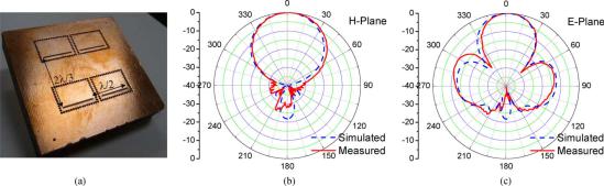
Fig. 9. (a) Inset: photo of the fabricated 2 22 filter/antenna array. Simulated and measured radiation patterns of the 2 22 filter/antenna array at the center frequency in (b) -plane and (c) -plane.
measured gain is 6.0 dBi, which is very close to the simulated 6.1 dBi. Therefore, the antenna efficiency is found to be 95% by taking the ratio between the measured gain and simulated directivity. The radiation patterns in both H- and E-planes are shown in Fig. 8. Very close agreement is found between the simulated and measured results.
A 2  2 filter/antenna array is fabricated and shown in Fig. 9(a). The spacing between antenna elements is

 in H-plane and


 in E-plane. To measure the array, a four-way power divider is used to split the input power equally and feed each array element. By calibrating the loss of the power divider and connecting cables, the measured gain is 11.4 dBi, which is 0.3 dB lower than the simulated 11.7 dBi. The radiation patterns in both H- and E-planes of the array are shown in Fig. 9(b) and (c), respectively. Again, very close agreement is apparent between simulation and measurement.
V. CONCLUSION
A three-pole vertical cavity filter has been seamlessly integrated with a slot antenna. A synthesis method has been proposed to achieve the same response from the integrated filter/antenna. At the same time, good radiation characteristic is also achieved. Using the proposed integration method, the antenna exhibits zero-added volume and high efficiency. The integrated
filter/antenna has a small footprint, and therefore antenna arrays without grating lobes can be realized with high- filtering functions. A four-element array of the proposed structure has also been successfully demonstrated. This technique could be extended for large phased-array antennas with increased efficiency and reduced co-site interference. The thickness/volume/weight of the filter/antenna can be further reduced using substrates with higher dielectric constant.
REFERENCES
[1]L. Harle and L. P. B. Katehi, “A vertically integrated micromachined filter,” IEEE Trans. Microw. Theory Tech., vol. 50, no. 9, pp. 2063–2068, Sep. 2002.
[2]K. Ahn and I. Yom, “A Ka-band multilayer LTCC 4-pole bandpass filter using dual-mode cavity resonators,” in IEEE MTT-S Int. Microw. Symp. Dig., Jun. 2008, pp. 1235–1238.
[3]J. H. Lee, N. Kidera, G. Dejean, S. Pinel, J. Laskar, and M. M. Tentzeris, “A V-band front-end with 3-D integrated cavity filters/duplexers and antenna in LTCC technologies,” IEEE Trans. Microw. Theory Tech., vol. 54, no. 7, pp. 2925–2936, Jul. 2006.
[4]Y. Yusuf and X. Gong, “Compact low-loss integration of high- 3-D filters and highly efficient slot antennas,” IEEE Trans. Microw. Theory Tech., 2011, to be published.
[5]R. J. Cameron, C. M. Kudsia, and R. R. Mansour, Microwave Filters for Communication Systems: Fundamentals, Design, and Applications. Hoboken, NJ: Wiley, 2007, ch. 11.
[6]“Simplified filter tuning using time domain,” Agilent Technologies Corp., Palo Alto, CA, Appl. Note 1287-8, 2001.