

диафрагмированные волноводные фильтры / 91e2047d-0522-479d-823b-1edd83468720
.pdf1320 |
IEEE TRANSACTIONS ON INSTRUMENTATION AND MEASUREMENT, VOL. 63, NO. 5, MAY 2014 |
Novel Tunable Filter for Millimeter-Wave Spectrum Analyzer Over 100 GHz
Takashi Kawamura, Hiroshi Shimotahira, and Akihito Otani, Member, IEEE
Abstract— Rapid progress in millimeter-wave wireless communication technologies requires accurate spectrum analysis in the frequency domain over 100 GHz. A tunable preselection filter is a key device in building such a spectrum analyzer. This paper proposes a new tunable filter as a preselector in the frequency range from 110 to 140 GHz. The filter was designed using a commercial electromagnetic simulator and two prototypes were evaluated. The first proved the tuning function in the working range but had a large insertion loss of >15 dB. The second with various structural and manufacturing improvements achieved both tunability and insertion loss of <10 dB.
Index Terms— Fabry–Perot resonator, millimeter-wave (MMW), preselector, spectrum analyzer, tunable filter.
I. INTRODUCTION
MANY millimeter-wave (MMW) applications, such as wireless personal area networks [1], remote monitoring of vital signs [2], and nondestructive testing and evaluation [3],
have been developed recently, but there are no established techniques to evaluate second harmonics generated in the frequency interval from 60 to 70 GHz, or wireless signals over 100 GHz. Conventionally, signals over 100 GHz are downconverted by a frequency mixer using a higher harmonic-wave mixing method and then fed to a low-frequency spectrum analyzer. However, in this measurement system, target signals are often buried in noise, making accurate evaluation difficult due to the low frequency-conversion efficiency of the harmonic mixer, and multiple image responses caused by the higher harmonic-wave mixing. Hence, a spectrum analyzer with high sensitivity and precise accuracy is needed urgently for such applications. A promising solution is a spectrum analysis system consisting of a frequency mixer using a fundamental wave mixing method for down conversion [4], a high-stability oscillator above 100 GHz as the fundamental wave source, and a commercially available spectrum analyzer. The preselector in the down-converter must satisfy two functions: 1) a wide tuning range of 30 GHz and 2) a small insertion loss of <10 dB.
The well-known and commercially available yttrium–iron garnet tuned filter (YTF) [5], [6] preselector for the MMW
Manuscript received June 14, 2013; revised August 23, 2013; accepted November 4, 2013. Date of publication January 22, 2014; date of current version April 3, 2014. This work was supported by the Research and Development Program through the Ministry of Internal Affairs and Communications, Japan. The Associate Editor coordinating the review process was Dr. Sergey Kharkovsky.
The authors are with the Research and Development Center, Research and Development Division, Anritsu Corporation, Kanagawa 243-8555, Japan (e-mail: takashi.kawamura@anritsu.com).
Color versions of one or more of the figures in this paper are available online at http://ieeexplore.ieee.org.
Digital Object Identifier 10.1109/TIM.2014.2298258
applications does not work above 100 GHz. In addition, the YTF has several drawbacks, because it consumes huge power, its center frequency fluctuates due to environmental temperature changes or aging, and its insertion loss is too large for use in spectrum analysis. From the viewpoint of tunability, liquid crystal (LC) devices [7], [8] and Fabry–Perot resonators [9] have attracted much attention, but available LC materials are lossy and their variable permittivity range is inadequate to achieve a sufficient tuning range. Moreover, Fabry–Perot resonators in free space are too large to fit in a normal spectrum analyzer.
As a solution, we propose a new tunable preselection filter in the frequency range from 110 to 140 GHz [10], [11]. The filter has a rectangular waveguide with Fabry–Perot resonator and the resonator length is changed mechanically to choose a specific spectral element. We developed the filter in two steps. First, we aimed to verify the frequency tuning function and to establish a method for manufacturing and assembling the filter. For ease of accurate machining, the first prototype had half-mirrors made of silicon (Si) substrates and waveguides of brass and stainless steel. The tuning function in the filter working range was validated but a large insertion loss of >15 dB was observed. Second, based on the first prototype results, we aimed to achieve an insertion loss of <10 dB. Instead of the Si half-mirrors, which seemed to be a cause of the large loss, metallic half-mirrors were used, giving a sufficiently small loss of <3 dB. Next, the second prototype was developed and evaluated with various structural and manufacturing improvements to reduce loss further.
Section II of this paper describes the operation principle of the proposed filter. Section III explains the design of the first prototype using an electromagnetic simulator along with the operation. Section IV explains the fabrication of the first prototype. Section V describes evaluation of the first prototype tuning function, as well as the larger-than-expected insertion loss. Section VI discusses the causes of the loss and proposes metallic half-mirrors to reduce it. Section VII evaluates the second prototype tuning function from 110 to 140 GHz and the insertion loss of <10 dB in the filter working range.
II. OPERATION PRINCIPLE
In a Fabry–Perot resonator, two half-mirrors face each other. When the distance between them (resonator length) is equal to one half the incident wavelength, the transmittance becomes maximum. Therefore, changing the resonator length changes the filter passband. If the variable range of the resonator
0018-9456 © 2014 IEEE. Personal use is permitted, but republication/redistribution requires IEEE permission. See http://www.ieee.org/publications_standards/publications/rights/index.html for more information.

KAWAMURA et al.: NOVEL TUNABLE FILTER FOR MMW SPECTRUM ANALYZER |
1321 |
TABLE I
SIMULATION CONDITIONS AND Q VALUE BY (1)
Fig. 1. Schematic view of proposed filter.
length is sufficiently large, a wideband tunable filter becomes possible.
In general, Fabry–Perot resonators are classified into three types: 1) confocal; 2) concentric; and 3) parallel plate, according to the half-mirrors. The confocal type has two half-mirrors sharing a focal point and is common due to its easy adjustment. However, the resonance finesse decreases rapidly with small changes in resonator length, so this type is unsuitable as a tunable filter. The parallel-plate type with no focal point is suitable for tuning, but has two issues in free space. First, an incident wave to the half-mirrors must be planar with the wavefront parallel to them. A spherical wave or a planar wave with oblique wavefront does not meet this condition, so the resonance finesse drops due to phase mismatch at the mirrors. Second, the radiation loss due to diffraction is large. Horn antennas with large apertures can be used to apply a planar wave to the mirrors, but such antennas are hard to fit in a normal spectrum analyzer size. Metallic-plate covers can be fitted around the mirrors to suppress radiation loss, but reflections from the covers disturb the phase at the mirrors and lower the resonance finesse.
To solve these issues, we propose fitting a rectangular waveguide with a Fabry–Perot resonator. Fig. 1 shows a schematic view for the proposed filter. Two half-mirrors are constructed in a single, TE10, mode rectangular waveguide. If the guide wavelength corresponding to the center frequency fc of the desired passband is λg , the resonator length L is set to one half of λg. In this configuration, since only the TE10 mode propagates in the waveguide, the propagation distance of the transmitted wave is uniquely defined and the phase of the electric field in the waveguide is adjusted without a special device to input a planar wave to the halfmirrors. Moreover, the filter is free from radiation loss because it is closed, and is also free from common YTF fc instability, because the temperature dependence of the dimensions for a metallic waveguide is negligible compared with λg .
The fundamental operation of the proposed filter was examined by computer simulations under the conditions in Table I. For simplicity, the waveguide and half-mirrors were assumed to be lossless. The half-mirror described in Section III consists of a dielectric substrate with a deposited metallic pattern. The resonator length L was set to one half of λg of the TE10
Fig. 2. Simulated frequency characteristics of proposed filter.
mode at fc = 125 GHz. Considering that the resonator is in the waveguide, the following formula is derived for the value of Q and the derivation is given in the Appendix:
|
L |
|
2 |
|
|
√ |
|
|
|
|
|
|
π |
R |
|
||||
Q = 1 + |
|
|
F, |
F = |
|
|
|
(1) |
|
a |
1 − R |
||||||||
where F is resonance finesse for |
a Fabry–Perot resonator |
||||||||
in free space. The value of Q representing the resonance finesse is defined as fc/Δ f where f is the full-width halfmaximum (FWHM) of the filter. Fig. 2 shows the simulated frequency characteristics for the proposed filter. The obtained center frequency of 127.1 GHz and the Q value of 514 were within 2% of the designated values of 125 GHz and 505, respectively, proving that the proposed filter works as expected and functions as a Fabry–Perot resonator. All simulations used CST MICROSTRIPES based on the transmission line matrix method.
III. FIRST PROTOTYPE DESIGN AND SIMULATION
The first prototype was developed mainly to validate the tuning function. A top priority for the prototype was assuring the processing accuracy of each part due to short wavelengths over 100 GHz. In particular, the filter-performance-critical half-mirrors demanded superior accuracy, so they were fabricated using fine semiconductor device processing technologies.
As shown in (1), the half-mirror reflectivity R determines the pass-bandwidth or resonance finesse, so R should be

1322 |
|
|
|
|
|
|
IEEE TRANSACTIONS ON INSTRUMENTATION AND MEASUREMENT, VOL. 63, NO. 5, MAY 2014 |
||||||||||||||||||||||||||||||
|
|
|
|
|
|
|
|
|
|
|
|
|
|
|
|
|
|
|
|
|
|
|
|
|
|
|
|
|
|
|
|
|
|
|
|
|
|
|
|
|
|
|
|
|
|
|
|
|
|
|
|
|
|
|
|
|
|
|
|
|
|
|
|
|
|
|
|
|
|
|
|
|
|
|
|
|
|
|
|
|
|
|
|
|
|
|
|
|
|
|
|
|
|
|
|
|
|
|
|
|
|
|
|
|
|
|
|
|
|
|
|
|
|
|
|
|
|
|
|
|
|
|
|
|
|
|
|
|
|
|
|
|
|
|
|
|
|
|
|
|
|
|
|
|
|
|
|
|
|
|
|
|
|
|
|
|
|
|
|
|
|
|
|
|
|
|
|
|
|
|
|
|
|
|
|
|
|
|
|
|
|
|
|
|
|
|
|
|
|
|
|
|
|
|
|
|
|
|
|
|
|
|
|
|
|
|
|
|
|
|
|
|
|
|
|
|
|
|
|
|
|
|
|
|
|
|
|
|
|
|
|
|
|
|
|
|
|
|
|
|
|
|
|
|
|
|
|
|
|
|
|
|
|
|
|
|
|
|
|
|
|
|
|
|
|
|
|
|
|
|
|
|
|
|
|
|
|
|
|
|
|
|
|
|
|
|
|
|
|
|
|
|
|
|
|
|
|
|
|
|
|
|
|
|
|
|
|
|
|
|
|
|
|
|
|
|
|
|
|
|
|
|
|
|
|
|
|
|
|
|
|
|
|
|
|
|
|
|
|
|
|
|
|
|
|
|
|
|
|
|
|
|
|
|
|
|
|
|
|
|
|
|
|
|
|
|
|
|
|
|
|
|
|
|
|
|
|
|
|
|
|
|
|
|
|
|
|
|
|
|
|
|
|
|
|
|
|
|
|
|
|
|
|
|
|
|
|
|
|
|
|
|
|
|
|
|
|
|
|
|
|
|
|
|
|
|
|
|
|
|
|
|
|
|
|
|
|
|
|
|
|
|
|
|
|
|
|
|
|
|
|
|
|
|
|
|
|
|
|
|
|
|
|
|
|
|
|
|
|
|
|
|
|
|
|
|
|
|
|
|
|
|
|
|
|
|
|
|
|
|
|
|
|
|
|
|
|
|
|
|
|
|
|
|
|
|
|
|
|
|
|
|
|
|
|
|
|
|
|
|
|
|
|
|
|
|
|
|
|
|
|
|
|
|
|
|
|
|
|
|
|
|
|
|
|
|
|
|
|
|
|
|
|
|
|
|
|
|
|
|
|
|
|
|
|
|
|
|
|
|
|
|
|
|
|
|
|
|
|
|
|
|
|
|
|
|
|
|
|
|
|
|
|
|
|
|
|
|
|
|
|
|
|
|
|
|
|
|
|
|
|
|
|
|
|
|
|
|
|
|
|
|
|
|
|
|
|
|
|
|
|
|
|
|
|
|
|
|
|
|
|
|
|
|
|
|
|
|
|
|
|
|
|
|
|
|
|
|
|
|
|
|
|
|
|
|
|
|
|
|
|
|
|
|
|
|
|
|
|
|
|
|
|
|
|
|
|
|
|
|
|
|
|
|
|
|
|
|
|
|
|
|
|
|
|
|
|
|
|
|
|
|
|
|
|
|
|
|
|
|
|
|
|
|
|
|
|
|
|
|
|
|
|
|
|
|
|
|
|
|
|
|
|
|
|
|
|
|
|
|
|
|
|
|
|
|
|
|
|
Fig. 4. E-plane cross-sectional view of first prototype.
TABLE II
Fig. 3. Simulated frequency characteristics of half-mirror.
PROTOTYPE SPECIFICATIONS
designed to meet the specified filter frequency characteristics. As an example, the following describes the half-mirror design to hold Q constant in the filter working range.
If fc and f are 120 GHz and 300 MHz, respectively, Q is 400, and a value for R of 0.99, −0.04 dB is required. Since a value of R near 0 dB is hard to simulate exactly, rather than using R, the transmittance S21 was chosen as the target parameter with a target value of about −20 dB. To achieve flatness for S21, first, we confirmed that a capacitive window on a metallic plate and a dielectric substrate of a certain permittivity and thickness had slopes of opposite sign for S21. Therefore, combining these two should cancel the frequency dependence of S21. Using trial and error on figures for the capacitive window and the dielectric properties of
the |
substrate, we finally |
obtained the half-mirror imposed |
in |
Fig. 3, consisting of |
a 110-μm-thick Si substrate with |
1-μm-thick Au capacitive window with a width of 70 μm. The simulated frequency characteristics of the half-mirror embeded in the WR-8 waveguide are shown in Fig. 3, and the value of S21 is between −20.26 and −20.16 dB in the filter working range and consequently Q is between 360 and 390, indicating the required half-mirror was obtained. The impact of processing errors in the half-mirror, 70 ± 5 μm in the window width, 1 ± 0.2 μm in the Au film, and 110 ± 20 μm in the substrate thickness was estimated by simulations. The variation of S21 and Q in the filter working range increased by 0.5 dB and by a factor of three, respectively. Precise control of the substrate thickness was critical to decrease variation in Q. In addition, a half-mirror with any frequency characteristics gradient can be designed by adjusting the capacitive window width and substrate thickness.
Fig. 4 shows an E-plane cross section of the prototype and Table II lists the main specifications. There are two inner waveguides (one fixed and the other movable) in an outer waveguide to change the resonator length L. Chokes prevent a wave passing through the gap of 10 μm between the outer and inner movable waveguides. The outer waveguide and the fixed inner waveguide are brass for easy production, whereas the inner movable waveguide, which is thinner than the other guides and may be damaged during assembly, is stainless steel to assure sufficient stiffness. The impact of assembly error
was estimated by simulations. About 5 μm of misalignment between the outer and inner movable waveguides shifted the center frequency fc of the passband by 100 MHz and increased the insertion loss by 0.1 dB. Calculating the impact of environmental temperature change, the resonator lengthened by
±1 μm and fc moved by ± 70 MHz at a temperature change of 25 ± 5 ◦C, where the thermal expansion coefficient of brass and stainless steel is 20.5 × 10⁻⁶/ °C and 10.4 × 10⁻⁶/ °C, respectively, and the thermally affected waveguide length was 20 mm. Since the FWHM of the passband is 300 MHz, the change of fc is acceptable for practical use of the proposed filter as a preselector. Producing waveguides using the same materials seems effective in reducing temperature sensitivity.
The simulations for the prototype when L was set to 1.25, 1.45, and 1.75 mm assigned 137.2, 123.4, and 108.8 GHz to the center frequency, and 14.2, 11.2, and 10.3 dB to the insertion loss. Although insertion loss increased near 140 GHz (L = 1.25 mm), a tuning function was validated. We fabricated a prototype MMW tunable filter based on these simulations.
IV. FIRST PROTOTYPE FABRICATION
Fig. 5 shows an overview of the first prototype. The halfmirrors were fabricated by semiconductor lithography, and conductive glue containing Ag paste was used to attach them
KAWAMURA et al.: NOVEL TUNABLE FILTER FOR MMW SPECTRUM ANALYZER |
1323 |
Fig. 5. Overview of first prototype.
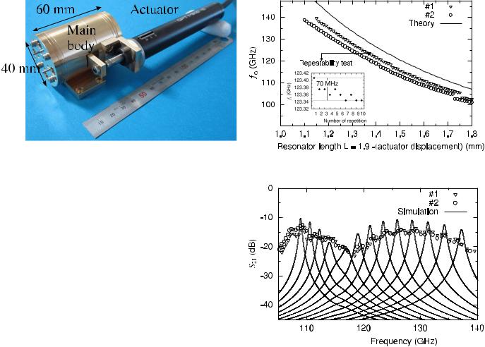
Fig. 6. Tunability test with fc as function of L.
to the inner waveguides. The processing error in the window width was ±2 μm, and the absolute value of the substrate thickness were in 99 ± 5 μm. A microscope was used in the assembly process to keep the gap uniformity. The external actuator moves the inner movable waveguide to change the resonator length and tune the frequency. To interface with a measurement system, EIA standard WR-8 waveguides are used to match UG-387/UM flanges in the US MIL standard. The filter without actuator measures 40 × 60 mm. Two prototypes #1 and #2 were fabricated to verify individual differences.
V. FIRST PROTOTYPE EVALUATION
An Anritsu 37169A vector network analyzer (VNA) was used to measure the frequency characteristics of the two fabricated MMW tunable filters. Since the VNA upper frequency is limited to 40 GHz, an OML VNA extender was used to extend the measurement range to 140 GHz.
Fig. 6 shows the passband center frequency fc when the resonator length L is changed in 10-μm steps. Measurements for the two prototypes as well as the theoretical fc as a function of L are plotted. Note that L in experiments is obtained by subtracting the actuator displacement from the initial resonator length of 1.9 mm. The theoretical curve shifted to the left and matched the experiments, indicating the required filter tunability was achieved. Differences between prototypes #1 and #2 seem to be due to fabrication differences.
To examine the measurement error of prototype #1, fc versus L was measured 10 times. As shown in the graph imposed in Fig. 6, the value of fc at L ≈ 1.4 mm was in the range of 70 MHz at 125 GHz. This scatter is consistent with the 2-μm repeatability of the external actuator. Since a change in L of 1 μm causes a shift in fc of 70 MHz near 120 GHz, the distribution can be explained by actuator repeatability and we concluded measurement errors in fc are ≤ 70 MHz. In this paper, the center frequency fc is defined as ( fR + fL )/2, where fR and fL are the frequencies at both edges of S21 with 3-dB bandwidth.
The prototype insertion losses expressed as the maximum value of S21 as a function of fc (and L) are plotted in Fig. 7. The solid lines show the simulated S21 frequency characteristics when L is changed in 50-μm steps. Comparing
Fig. 7. Measured insertion losses and simulated frequency characteristics.
measurements with simulations, a global and a local point are noteworthy. Globally, the measured losses are 5-dB larger than the simulated losses in the filter working range from 110 to 140 GHz. Locally, although the half-mirrors were designed for constant insertion losses in the working range, both the measured and simulated losses dropped significantly near 116 GHz.
The above measurements and discussions validate the tuning function while clarifying issues to solve. The following sections examine the second prototype, targeting an insertion loss of <10 dB.
VI. TRIAL TO IMPROVE INSERTION LOSS
A. Analysis of Excess Loss Near 116 GHz
The excess loss near 116 GHz is ascribed to mode conversion from longitudinal section electric 10 (LSE10) to LSE11 at the gap exit (Fig. 4). The width and height of the resonator part are larger than those of the WR-08 waveguide by the thickness of the inner waveguide walls, and the increase makes the LSE11-mode propagating rather evanescent in the resonator part. Figs. 8 and 9 show the simulated loss characteristics and power in LSE11-mode with the variable height b and fixed width a, respectively. For each value of b, the loss

1324 |
|
|
|
|
|
IEEE TRANSACTIONS ON INSTRUMENTATION AND MEASUREMENT, VOL. 63, NO. 5, MAY 2014 |
||||||||||||
|
|
|
|
|
|
|
|
|
|
|
|
|
|
|
|
|
|
|
|
|
|
|
|
|
|
|
|
|
|
|
|
|
|
|
|
|
|
|
|
|
|
|
|
|
|
|
|
|
|
|
|
|
|
|
|
|
|
|
|
|
|
|
|
|
|
|
|
|
|
|
|
|
|
|
|
|
|
|
|
|
|
|
|
|
|
|
|
|
|
|
|
|
|
|
|
|
|
|
|
|
|
|
|
|
|
|
|
|
|
|
|
|
|
|
|
|
|
|
|
|
|
|
|
|
|
|
|
|
|
|
|
|
|
|
|
|
|
|
|
|
|
|
|
|
|
|
|
|
|
|
|
|
|
|
|
|
|
|
|
|
|
|
|
|
|
|
|
|
|
|
|
|
|
|
|
|
|
|
|
|
|
|
|
|
|
|
|
|
|
|
|
|
|
|
|
|
|
|
|
|
|
|
|
|
|
|
|
|
Fig. 8. Simulated loss characteristics due to mode conversion at gap exit.
Fig. 9. Simulated power in LSE11-mode.
and PLSE11 is maximal slightly above the cutoff frequency of the LSE11-mode. Hence, proper rescaling of the wall thickness is required to push the cutoff frequency out of the working range. Note that in this simulation the calculated scattering matrix elements S11 and S21 of LSE10-mode define the loss in decibel as −10 log10 |S11|2 + |S21|2 .
B. Improvement of Global Loss
Fig. 10. Simulated frequency characteristics of all-gilded waveguides model.
Fig. 11. Structure of metallic half-mirror used in second prototype. (a) Side view. (b) Front view.
Achieving the specified frequency characteristics as faithfully as possible is an important aim of the half-mirror design. Fig. 11(a) and (b) shows the side and front of the metallic half-mirrors, respectively. The mirror has two design variables: 1) the metallic stub thickness Wm and 2) the capacitive window width Ws . Fig. 12 shows that the flatness or the variation of S21 in the filter working range can be controlled by Wm , and when Wm = 0.65 mm, the mirror has minimum variation of ±0.2 dB in the range. Fig. 13 shows that the global S21 is controlled by Ws , that is, the narrower the Ws , the lower the S21. Consequently, assigning appropriate values to Wm and Ws provides the half-mirrors S21 frequency characteristics with desired slope and magnitude.
The global loss increase can be attributed partly to the relatively low conductivity of metals used in the waveguides. Brass (σ = 2.74 × 10⁷ S/m) was used to ease production, whereas stainless steel (σ = 1.6 × 10⁶ S/m) was used to maintain stiffness. To examine the effect of a change in materials on loss reduction, the frequency characteristics were recalculated assuming that the half-mirrors were Si, but that all waveguides were gold (σ = 4.5 × 10⁷ S/m). Comparing the results in Fig. 10 with Fig. 7, an improvement in loss of about 4 dB can be expected if the waveguide surfaces are all gilded.
To ensure processing accuracy, the first prototype uses Si substrate half-mirrors but Si has high permittivity and its dielectric loss is thought to cause the global loss. Hence, a nondielectric metallic half-mirror is a good candidate to improve loss.
C. Prototype Fixed Center Frequency Filter and
Estimated Material Constant
To improve the global insertion loss, replacing the waveguides and half-mirrors with those of higher conductivity is surely effective. However, first the uncertainty problem in the material constants used in the simulation should be resolved, because the measured and simulated insertion losses in Fig. 7 exhibit discrepancy of 5 dB. Hence, a filter without tuning mechanics and hence with a fixed center frequency was prototyped to identify the appropriate conductivity value for the filter design.
An overview of the fixed frequency filter and its E-plane cross-sectional view are shown in Figs. 14 and 15, respectively.
It is made |
of |
brass and |
the surfaces of the waveguides |
|
and |
mirrors |
are |
all gilded. The resonator length L is set |
|
to |
1.707 mm, |
giving a |
center frequency of 116 GHz. |
|

KAWAMURA et al.: NOVEL TUNABLE FILTER FOR MMW SPECTRUM ANALYZER |
1325 |
||||||||
|
|
|
|
|
|
|
|
|
|
|
|
|
|
|
|
|
|
|
|
|
|
|
|
|
|
|
|
|
|
|
|
|
|
|
|
|
|
|
|
|
|
|
|
|
|
|
|
|
|
|
|
|
|
|
|
|
|
|
|
|
|
|
|
|
|
|
|
|
|
|
|
|
|
|
|
|
|
|
|
|
|
|
|
|
|
|
|
|
|
|
|
|
|
|
|
|
|
|
|
|
|
|
|
|
|
|
|
|
|
Fig. 12. Metallic half-mirror S21 characteristics with stub thickness Wm as parameter.
Fig. 14. Overview of fixed frequency filter.
Fig. 13. Metallic half-mirror S21 characteristics with capacitive window width Ws as parameter.
The half-mirror, as well as in Fig. 3, is a capacitive window |
Fig. 15. E-plane cross-sectional view of fixed frequency filter. |
|
(Ws ) of 0.06-mm width, but its thickness (Wm ) of 0.5 mm |
||
|
||
is extremely enlarged to achieve the required transmittance |
|
|
without the help of dielectric substrate. Simulation of this |
|
|
structure gives S21 of −19.4 dB at 116 GHz, similar to that |
|
|
in Fig. 3. |
|
|
Squares in Fig. 16 show the measured S21 of the fixed |
|
|
frequency filter and the low insertion loss of 2 dB is clear. |
|
|
A tunable filter with this metallic half-mirror probably has a |
|
|
lower loss than the first prototype, even taking into account |
|
|
the loss increase due to the tuning mechanism. Repeating |
|
|
the simulations with the conductivity σ for gold showed |
|
|
the simulated transmittance matched the measurement when |
|
|
σ = 4.7 × 10⁷ S/m (Fig. 16). Using this conductivity offers |
|
|
more reliable simulations for the proposed filter. |
|
VII. DESIGN AND EVALUATION OF SECOND PROTOTYPE
The ideas for loss reduction in Section VI were incorporated in the second prototype design. Thickening the walls of the inner waveguides from 0.24 to 0.38 mm moved the LSE11-mode cutoff frequency out of the filter working range, from 116.7 to 100.1 GHz. All surfaces in the resonator were assumed to be gilded and the metallic half-mirrors described
Fig. 16. Comparison between measured and simulated S21 characteristics.
in Section VI-C were used. Fig. 17 shows simulated frequency characteristics of the redesigned prototype when the resonator length was changed in 50-μm steps. The loss characteristics between 110 and 140 GHz are almost flat and the excess

1326 |
|
|
|
|
IEEE TRANSACTIONS ON INSTRUMENTATION AND MEASUREMENT, VOL. 63, NO. 5, MAY 2014 |
|||||||||||
|
|
|
|
|
|
|
|
|
|
|
|
|
|
|
|
|
|
|
|
|
|
|
|
|
|
|
|
|
|
|
|
|
|
|
|
|
|
|
|
|
|
|
|
|
|
|
|
|
|
|
|
|
|
|
|
|
|
|
|
|
|
|
|
|
|
|
|
|
|
|
|
|
|
|
|
|
|
|
|
|
|
|
|
|
|
|
|
|
|
|
|
|
|
|
|
|
|
|
|
|
|
|
|
|
|
|
|
|
|
|
|
|
|
|
|
|
|
|
|
|
|
|
|
|
|
|
|
|
|
|
|
|
|
|
|
|
|
|
|
|
|
|
|
|
|
|
|
|
|
|
|
|
|
|
|
|
|
|
|
|
|
|
|
|
|
|
|
|
|
|
|
|
|
|
|
|
|
|
|
|
|
|
|
|
|
|
|
|
|
|
|
|
|
|
|
|
|
|
|
|
|
|
|
|
|
|
|
|
|
|
|
|
|
|
|
|
|
|
|
|
|
|
|
|
|
|
|
|
|
|
|
|
|
|
|
|
|
Fig. 19. Tunability test with fc as function of L.
Fig. 17. Simulated frequency characteristics of redesigned prototype..
Fig. 18. Overview of second prototype.
loss around 116 GHz disappears. The two key functions for a preselector—frequency tunability and small loss—are fully satisfied in this simulation.
Fig. 18 shows an overview of the second prototype. All surfaces in the resonator could be gilded by changing the manufacturing and assembly procedures. The metallic halfmirror was integrated into the inner waveguide. The filter dimensions are 20 × 20 × 52 mm3 without the tuning actuator.
The same measurements were made on the second prototype as on the first. The tunability test results in Fig. 19 clearly validate the tuning function between 110 and 140 GHz and the repeatability of the center frequency fc of the passband was 125 MHz. The measured insertion loss characteristics in Fig. 20 show slowly changing behavior and are <10 dB in the working range and obtained S11 at fc was about −5 dB. Consequently, the second prototype satisfies the key preselector functions. As shown in Fig. 20, the loss characteristics are much improved compared to the
Fig. 20. Improvement of loss characteristics between first and second prototypes.
first prototype. However, there is some increase in loss near 116 GHz and slightly growing loss toward 110 GHz. Solving these remain for future work.
VIII. CONCLUSION
This paper proposes using a tunable filter as a preselector for a MMW spectrum analyzer. The filter has a rectangular waveguide with Fabry–Perot resonator and changes the resonator length mechanically to specify the frequency. Computer simulations were used to design the half-mirrors, validating the operation principle and tunability in the frequency range from 110 to 140 GHz.
The first prototype validated the tuning function between 110 and 140 GHz but the required insertion loss of <10 dB was out of reach. The excess loss near 116 GHz could be eliminated by thickening the inner waveguides wall, shifting the LSE11-mode cutoff frequency out of the working range. The global loss was reduced by changing the filter materials from brass, stainless steel, and Si to gold. A metallic halfmirror design without dielectric was proposed to achieve the specified frequency characteristics. Evaluation of the fixed frequency filter with this metallic half-mirror validated the loss

KAWAMURA et al.: NOVEL TUNABLE FILTER FOR MMW SPECTRUM ANALYZER
reduction and clarified that the conductivity 4.7 × 10⁷ S/m for gold was appropriate for the simulation. The second prototype incorporating these improvements achieved the key preselector functions with tunability between 110 and 140 GHz and a loss of <10 dB. Excess losses near 110 and 116 GHz and improvement of tuning repeatability remain for future solutions.
APPENDIX
DERIVATION OF (1)
A Fabry–Perot resonator in a rectangular waveguide has transmittance S21 as follows [12]:
S21 = |
|
|
1 |
|
|
(2) |
|
1 + |
2F |
2 |
sin |
2 |
|
||
|
π |
|
|
(kz L) |
|||
where kz L means one-way phase rotation in the resonator, and the wavenumber in the resonator kz and that in free space k are related by
kz = |
k2 |
− (π /a)2 |
, k = |
kz2 + (π /a)2 |
. |
|||||
|
|
|
|
|
|
|
|
|
|
|
The value of Q is written as |
|
|
|
|
|
|||||
|
|
fc |
|
fc |
|
|
kc |
|||
Q = |
|
= |
|
= |
|
|
||||
f |
f+ − f− |
k+ − k− |
||||||||
where, 2π f = c0 k, c0 is the velocity of light, and subscripts c and ± mean that the subscripted quantities are at the center frequency and at two edges of the passband, respectively. The wavenumbers on the right-hand side are given by
kc = |
kz2,c + (π /a)2 |
|
|
|
|
|
|
|
|||
k± = |
kz,ck± |
k 2 |
|
+ (π/a)2 ≈ |
kc2 ± 2kz,c |
k |
|||||
|
|
z,c |
|
|
|
|
|
|
|
|
|
≈ kc ± |
|
k . |
|
|
|
|
|
|
|||
kc |
|
|
|
|
|
|
|||||
Hence, the value of Q is expressed by |
|
|
|||||||||
|
|
|
|
|
k2 |
|
1 |
|
|
|
|
|
|
Q ≈ |
|
c |
· |
|
. |
(3) |
|||
|
|
kz,c |
2 k |
||||||||
From (2), since the |
resonance condition gives kz,c L = π , |
||||
and S21 is halved at the two wavenumbers kz,± = kz,c ± |
k, |
||||
it holds that |
|
|
|
|
|
| sin(kz,c ± |
k)L| = |sin ( k L)| = |
π |
|
||
|
|
|
|||
2F |
|
||||
and assuming that |
k L 1, |
k = π/(2F L) is obtained. |
|||
Substituting these expressions |
for kc and |
k into (3), |
we |
||
obtain
|
kz2,c +(π/a)2 |
L |
L |
|
2 |
F . |
Q ≈ |
|
|
F = 1 + a |
|
|
|
kz,c |
π |
|
ACKNOWLEDGMENT
The authors would like to thank the members of the project advisory committee for their helpful discussions.
REFERENCES
[1] A. Hirata, T. Kosugi, H. Takahashi, R. Yamaguchi, F. Nakajima,
T.Furuta, et al., “120-GHz-band millimeter-wave photonic wireless link for 10-Gb/s data transmission,” IEEE Trans. Microw. Theory Technol., vol. 54, no. 5, pp. 1937–1944, May 2001.
[2]S. Bakhtiari, T. W. Elmer, N. M. Cox, N. Gopalsami, A. C. Raptis,
S.Liao, et al., “Compact millimeter-wave sensor for remote monitoring of vital signs,” IEEE Trans. Instrum. Meas., vol. 61, no. 3, pp. 830–841, Mar. 2012.
1327
[3]S. Kharkovsky, A. McClanahan, R. Zoughi, and D. D. Palmer, “Microwave dielectric-loaded rectangular waveguide resonator for depth evaluation of shallow flaws in metals,” IEEE Trans. Instrum. Meas., vol. 60, no. 12, pp. 3923–3930, Dec. 2011.
[4]M. Fuse, H. Sekiya, and A. Otani, “High-dynamic-range measurement of millimeter-wave amplifier using 140-GHz fundamental mixer,” in Proc. Asia-Pacific Microw. Conf., Dec. 2012, pp. 436–438.
[5]J. Helszajn, YIG Resonators and Filters. New York, NY, USA: Wiley, 1985.
[6]J. Uher and W. J. R. Hoefer, “Tunable microwave and millimeter-wave band-pass filter,” IEEE Trans. Microw. Theory Tech., vol. 39, no. 4, pp. 643–653, Apr. 1991.
[7]W. Fu, R. Dickie, R. Cahill, H. Gamble, Y. Ismail, V. Fusco, et al., “Liquid crystal tunable MM wave frequency selective surface,” IEEE Microw. Wireless Comput. Lett., vol. 17, no. 9, pp. 667–669, Sep. 2007.
[8]N. Tentiller, F. Krasinski, R. Sauleau, B. Splingart, H. Lhermite, and P. Coquet, “A liquid-crystal, tunable, ultra-thin Fabry-Perot resonator in Ka band,” IEEE Antennas Propag. Lett., vol. 8, no. 1, pp. 701–704, Aug. 2009.‘
[9]R. Sauleau, “Fabry Perot resonators,” in Encyclopedia of RF and Microwave Engineering, vol. 2. K. Chang, Ed. New York, NY, USA: Wiley, 2005, pp. 1381–1401.
[10]T. Kawamura and A. Otani, “Proposal on a novel tunable millimeterwave band filter,” Technical Papers on Instrumentation and Measurement, IEE-Japan, in Japanese, IM-12-004, Jan. 2012.
[11]T. Kawamura, H. Shimotahira, and A. Otani, “Novel tunable filter for millimeter-wave spectrum analyzer over 100 GHz,” in Proc. IEEE Int. Instrum. Meas. Technol. Conf., May 2013, pp. 641–646.
[12]M. Born and E. Wolf, Principles of Optics, 6th ed. New York, NY, USA: Pergamon, 1984, p. 327.
Takashi Kawamura received the B.E. and M.E. degrees in computer science and systems engineering from Yamaguchi University, Yamaguchi, Japan, in 1999 and 2001, respectively.
He joined Anritsu Corporation, Atsugi, Japan, in 2001, where he is currently involved in the research and development of spheroidal coupler and millimeter-wave filter.
Hiroshi Shimotahira received the B.E. degree in arts and sciences from the University of Tokyo, Tokyo, Japan, in 1983.
He has been an Engineer with Anritsu Corporation, Atsugi, Japan, since 1983. His current research interests include optical interferometric measurement.
Mr. Shimotahira is a member of the Optical Society of America.
Akihito Otani (M’10) was born in Fukuoka, Japan, in 1961. He received the B.E. degree from Miyazaki University, Miyazaki, Japan, and the Ph.D. degree from Saga University, Saga, Japan.
He has been with the Research and Development Center, since 2007, where he is currently a Senior Expert Research Engineer, and he was with the Technology Management Center, Anritsu Corporation, Atsugi, Japan, as a Senior Manager. His current research interests include high-speed optical transmission, optical signal processing, nonlinear optics,
optical sampling, mm-wave measurement technology, mm-wave device, mmwave transmission, and mm-wave application.
Dr. Otani is the international expert of IEC TC86/SC86C/WG1 and TC86/WG4. He is a member of the Optical Society of America. He is the Senior Member of the Institute of Electronics, Information, and Communication Engineers of Japan, and the Institute of Electrical Engineers of Japan. He is currently the Vice-Chairperson of the IEEJ Technical Committee on Instrumentation and Measurement, and IEEE Instrumentation and Measurement Society, Japan.