

диафрагмированные волноводные фильтры / 316bcb71-63e3-49ab-8172-d501448137f0
.pdfIEEE TRANSACTIONS ON ANTENNAS AND PROPAGATION, VOL. 56, NO. 1, JANUARY 2008 |
5 |
Use of the Dielectric Resonator Antenna as a
Filter Element
Eng Hock Lim, Student Member, IEEE, and Kwok Wa Leung, Senior Member, IEEE
Abstract—For the first time, the dielectric resonator antenna (DRA) is simultaneously used as a filtering device, named as the DRA filter (DRAF). The theory and design methodology of the DRAF are elucidated using the cylindrical DR. It was found that the operating frequency of the filter part can be made equal to, or different from, that of the antenna part. The return loss, input impedance, radiation patterns, and insertion loss of the DRAF are studied. To improve the insertion loss of the filter part, the DR is top-loaded by a metallic disk without significantly affecting the radiation efficiency of the antenna part. The disk, in addition, can be used to tune the frequency of the filter. It was found that the antenna and filter parts of the DRAF can be designed and tuned almost independently. A second-order DRAF is also designed in this paper. As the dual function DRAF is compact and cost effective, it should find applications in modern wireless communication systems.
Index Terms—Dielectric resonator antenna (DRA), filter, multifunction antenna.
I. INTRODUCTION
THE dielectric resonator (DR) has traditionally been used in filter and oscillator applications because its  -factor can be made very high [1], [2]. For designs of the DR filter (DRF),
an external metallic enclosure is usually used to reduce the radiation loss, at the cost of increasing the filter size. In 1983, Long and his collaborators [3] showed that the DR can also be used as an effective antenna. Since then, the DR antenna (DRA) has received much attention because of a number of advantages such as its small size, low loss, low cost, light weight, and ease of excitation.
Today, it is a trend to bundle multiple components into a single module for compact and multifunctional wireless communication systems [4], [5]. The concept of multifunction has been extensively explored to miniaturize RF modules [6]. In the system-in-package (SIP), system-on-chip (SOC), and low-tem- perature co-fired ceramics (LTCC) technologies, dielectric has been commonly used as the packaging material [6]–[8]. This leads to the study of the dual function DRA that simultaneously acts as the antenna and packaging cover [9]. There have been many works reported on the DRA [10]–[12] and DRF [13]–[15] separately. Thus far, however, no work has been carried out to combine the DRA and DRF using a single piece of DR. The
Manuscript received July 5, 2007; revised September 15, 2007. This work was supported by a CERG grant from the Research Grants Council of the Hong Kong Special Administrative Region, China (Project no.: CityU 116007).
E. H. Lim and K. W. Leung are with the Wireless Communications Research Centre and Department of Electronic Engineering, City University of Hong Kong, Kowloon, Hong Kong (email: eekleung@cityu.edu.hk).
Color versions of one or more of the figures in this paper are available online at http://ieeexplore.ieee.org.
Digital Object Identifier 10.1109/TAP.2007.913152
 -factor of the DRA is usually low to enhance the radiation and bandwidth, but that of the DRF is usually high to reduce the insertion loss. Because of the different
  -factor requirements, it is intuitively contradictory to implement the DRA and DRF using a single piece of DR. In this paper, a dual function DRA filter (DRAF) that combines the DRA and DRF is investigated for the first time. A cylindrical DR, loaded with a metallic disk, is utilized as the resonator for the antenna as well as for the bandpass filter. The metallic disk is used to improve the insertion loss of the DRF and to simultaneously tune the filter, with negligible effect on the radiation efficiency of the DRA. Use is made of the


 and
and 


 modes of the DR to design the DRF and DRA, respectively. Because of the orthogonality of the two modes, the antenna and filter parts of the DRAF can be designed and tuned separately and almost independently. It is found that the antenna and filter parts can also be designed at the same or different frequencies. The return loss, radiation pattern, antenna gain, insertion loss, and mutual coupling of the DRAF are investigated. Finally, a design of the second-order DRAF is given.
II. DRAF CONFIGURATION
Fig. 1 shows the proposed DRAF configuration, where a
cylindrical DR with radius |
, height |
, |
|
and dielectric constant |
is used. The DRA is working |
||
in its fundamental broadside |
mode at 2.68 GHz [16]. |
||
Satisfying the |
condition of |
[1], the |
fundamental |
endfire |
mode can be excited, which is at 3.095 GHz in |
||
our case. A circular metallic disk of radius |
is |
||
concentrically displaced at |
from the top of the DR. |
||
Conventional 50microstriplines of |
are etched |
||
on a Duroid substrate ( |
and thickness 0.762 mm) to |
||
couple/excite the DRF/DRA. Microstrips 1 and 2 are used to
excite the |
mode of the DR for the filter part. They have |
||
an offset of |
|
from the center of the DR, with |
|
matching stub lengths of |
|
. Microstrip 3 |
|
is a feedline for exciting the broadside |
mode of the |
||
DRA. It has a matching stub offset of |
, with an |
||
inclination angle of |
. |
|
|
The |
and |
field patterns of a cylindrical DR |
|
are sketched in Fig. 2. For ease of reference, the fields of the dominant 


 mode of a circular microstrip patch are also given in Fig. 2. With reference to Fig. 2(c), it is obvious that there are only TM modes in the patch due to the condition of


 [17], [18]. Owing to this limitation, the microstrip patch cannot be used to realize the new idea.
Fig. 3 shows the simulated mode chart for the funda-
mental endfire |
and |
broadside |
modes |
of a |
microstrip-fed |
cylindrical DR as a function of |
, |
with |
|
|
and |
. The HFSS models (50- |
||
0018-926X/$25.00 © 2008 IEEE

6 |
IEEE TRANSACTIONS ON ANTENNAS AND PROPAGATION, VOL. 56, NO. 1, JANUARY 2008 |
Fig. 3. Mode chart for the fundamental endfire TE

 and broadside HEM

 modes of a microstrip-fed cylindrical DR, with R
 = 10:5 mm. The insets show the topand side-view of the HFSS simulation models.
Fig. 1. Proposed first-order cylindrical DRAF: (a) top view and (b) front view.
Fig. 2. Electric and magnetic field patterns for: (a) TE

 mode of a cylindrical DR, (b) HEM

 mode of a cylindrical DR, (c) TM
 mode of a cylindrical microstrip patch antenna.
microstriplines, with substrate 


 and thickness 0.762 mm) are also shown in the insets, where the sideand centrally-coupling methods are used to excite the


 and
and 


 modes, respectively.
Fig. 4. Simulated and measured return losses, insertion losses, and coupling coefficients of the first-order cylindrical DRAF (Fig. 1). The inset shows the simulated and measured input impedances of the DRA.
III. RESULTS
The first-order DRAF in Fig. 1 was studied first. Ansoft HFSS was used to simulate the DRAF, and measurements were carried out to verify the simulations. For the  -parameter simulations using HFSS, iterations were made to give an error of less than 1% as specified in the input. In the measurements, all of the unused ports were terminated by 50-
 loads. Fig. 4 shows the simulated and measured return losses, insertion losses, and mutual couplings between different ports. We begin with the discussion of the filter (DRF) part. It was found from HFSS simulations that the


 mode cannot be properly excited when a dielectric resonator of


 was used. A higher dielectric constant, say


 , is needed to excite the


 mode efficiently. With reference to Fig. 4, the measured and simulated operating frequencies (minimum insertion loss) of the DRF are 3.054 and 3.095 GHz, respectively, with an error of 1.34%. The measured insertion loss is 2.19 dB, which has included the losses of the two SMA connectors and the feedlines
LIM AND LEUNG: USE OF THE DRA AS A FILTER ELEMENT
Fig. 5. Simulated and measured normalized radiation patterns of the first-order cylindrical DRAF (Fig. 1): (a) E-plane and (b) H-plane.
7
Fig. 6. Measured antenna gains of the first-order cylindrical DRAFs, with and without the loading metallic disk.
used in the experiment. Since each SMA connector has an insertion loss of about 0.15–0.2 dB over the frequency range, the measured result is in reasonable agreement with the simulated value of 1.6 dB (no connectors). The measured and simulated 3-dB passbands are 18 and 17 MHz, respectively. Both of the measured and simulated return losses at Port 1 (from 

 ) are 16 dB. The return loss at Port 2 was also studied. Similar results were obtained, which is expected because of the symmetry.
For the antenna (DRA) part (Port 3 in Fig. 1), the measured and simulated resonance frequencies (max. return loss) are given by 2.70 and 2.68 GHz (0.74%), respectively. As can be found from Fig. 4, the measured and simulated impedance bandwidths ( 


 ) are 3.68 and 3.35%, respectively. The measured and simulated input impedances of the DRA are shown in the inset, where good agreement between the simulation and measurement is obtained. The coupling between the DRA and DRF ports (

 ,
, 

 ) is in general weaker than 20 dB across the whole frequency range.
The measured and simulated radiation patterns of the DRA (Port 3 in Fig. 1) are illustrated in Fig. 5. The  - and
- and  -planes are defined at


 and
and 


 , respectively. With reference to the figure, a broadside mode is obtained, which is expected
for the fundamental |
mode. In the broadside direction |
|
( |
), the cross-polarized fields are weaker than their co-po- |
|
larized counterparts by at least 20 dB. Fig. 6 shows the measured antenna gain of the DRA as a function of frequency. As can be observed from the figure, the antenna gain is 


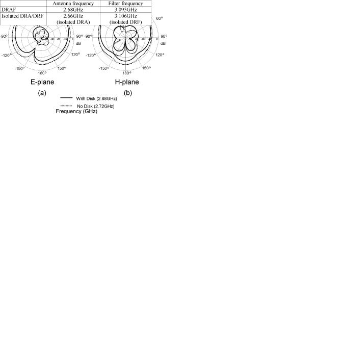
 at resonance. For comparison, the measured antenna gain with the metallic disk removed is also shown in the same figure. It is found that the metallic disk has only little effects on the antenna gain. The simulated radiation patterns for the two configurations (with and without the metallic disk) are compared in Fig. 7. With reference to the figure, the results of the two configurations are, again, similar to each other.
To investigate further, an isolated DRA without the filter part was constructed by removing Microstrips 1 and 2 from the DRAF in Fig. 1. Similarly, an isolated DRF was built by removing Microstrip 3. Table I compares the simulated resonance frequencies of the isolated DRA/DRF with those of the DRAF. As can be seen from the table, the resonance frequencies of the
Fig. 7. Simulated normalized radiation patterns of the first-order cylindrical DRAF: E-plane and (b) H-plane.
TABLE I
COMPARISON OF SIMULATED RESONANCE FREQUENCIES OF THE DRAF AND
OF THE ISOLATED DRA/DRF
antenna and filter parts of the DRAF are very close to those of the isolated DRA/DRF. It shows that designs of the antenna and filter parts can be done quite independently for the DRAF. It is due to the orthogonality of the electric fields of the 


 and
and 


 modes, as shown in Fig. 2.
Next, we concentrate on the filter part. Table II compares the loaded  -factor (
 ) and out-of-band rejection of the DRAF with those of contemporary bandpass filters. The
  -factor is calculated by using, where


 , where
  and
and 


 are the measured resonance frequency and 3-dB bandwidth [19], respectively. Obviously, the proposed DRAF has
a much higher  -factor than for the conventional microstripbased bandpass filters that have a higher conductor loss. Although the
  -factor of the DRAF is much lower than for the conventional cavity-encapsulated DRF [23], the DRAF has the advantage of being more compact. Of course, the DRAF can be further miniaturized by increasing the permittivity, but it is not

8 |
IEEE TRANSACTIONS ON ANTENNAS AND PROPAGATION, VOL. 56, NO. 1, JANUARY 2008 |
TABLE II
COMPARISON OF THE DRAF AND CONTEMPORARY BANDPASS FILTERS
Fig. 8. Effect of the height h of the metallic disk on the DRAF: (a) Resonance frequencies of the DRA and DRF as a function of h. (b) Minimum 20 log jS
 j (maximum return loss) and maximum 20 log jS
 j (minimum insertion loss) as a function of h.
the focus of this paper. The out-of-band-performance is found to be greater than 30 dB.
Fig. 8(a) shows the effect of the height  on the operating frequencies of the DRA and DRF. With reference to the figure, the DRA frequency increases from 2.65 to 2.72 GHz (2.64% increase), and the DRF frequency decreases from 3.23 to
Fig. 9. Effect of the radius R of the metallic disk on the DRAF: (a) Resonance frequencies of the DRA and DRF as a function of R
 . (b) Minimum 20 log jS
 j (maximum return loss) and maximum 20 log jS
 j (minimum insertion loss) as a function of R
 .
.
3.00 GHz (7.12% decrease), as  increases from 2 to 14 mm. The effect of
  on the return and insertion losses is studied in Fig. 8(b). It is noted that both the return and insertion losses can be improved by using a smaller
  . Fig. 9 shows the effect of the disk radius
  on the DRAF. As can be observed from Fig. 9(a), the DRA frequency decreases with, and the DRF frequency increases with, increasing
  . With reference to Fig. 9(b), both the return and insertion losses can be improved by using a larger disk. Obviously, the DRAF can be fine-tuned by varying the height and radius of the metallic disk, which is a very important feature for the filter [22], [24].
The previous design has different DRA and DRF frequencies. A DRAF was designed to show that the two frequencies can coincide with each other. Fig. 10 shows the simulated result, with
parameters |
, |
, |
, |
, |
, |
, |
, |
and |
. It should be mentioned that although the |
||
DRA and DRF operate at the same frequency, the coupling between them 


 is still very small,


 .
.
Next, the second-order DRAF using two disk-loaded DRs is studied. Fig. 11 shows the configuration. The optimized design

LIM AND LEUNG: USE OF THE DRA AS A FILTER ELEMENT
Fig. 10. Simulated return loss, insertion loss, and coupling coefficient of the disk-loaded cylindrical DRAF as a function of frequency. In this case, the DRA and DRF have the same operating frequency.
9
Fig. 12. Simulated return losses, insertion losses, and coupling coefficients of the second-order DRAF as a function of frequency.
Fig. 13. Simulated normalized radiation patterns of the second-order DRAF:
(a) E-plane and (b) H-plane.
Fig. 11. Top view of the second-order DRAF.
parameters are |
, |
, |
, |
, |
, |
, |
, |
|
, and |
|
. All |
of the microstrips are 50- lines. Ports 1, 2 are for the DRF, whereas Ports 3, 4 are for the DRA. Fig. 12 shows the simulated return losses, insertion losses, and coupling coefficients of the second-order DRAF. During the tuning process, it was found that the resonance modes of the DRA and DRF were almost independent of each other. The result is not surprising because of the orthogonality between the fields of the


 and
and 


 modes. Furthermore, Microstrips 1, 2 (filter ports) are normal to Microstrips 3, 4 (antenna ports), making the coupling between the microstrip lines very little. With reference to Fig. 12, the DRA frequency at Port 3 (or Port 4) is 2.71 GHz, which is only slightly higher than for the first-order version. Two modes are observed for the DRF, which is expected for a second-order bandpass filter. The out-of-band rejection of the DRF is much better than that of the first-order counterpart. Fig. 13 shows the simulated
  -plane (
 -plane) and
  -plane (
 -plane) radiation patterns. Again, in the broadside direction the co-polarized
fields are stronger than their cross-polarized counterparts by at least 20 dB. Finally, it should be mentioned that a higher-order DRAF can be obtained easily by increasing the number of DRs.
IV. CONCLUSION
The novel DRAF that simultaneously provides the antenna and filter functions has been proposed. Ansoft HFSS was used to simulate the DRAF. Measurements were carried out to verify the simulations, and good agreement between simulation and measurement has been found. In the design, the broadside 


 and endfire


 modes of the cylindrical DR are simultaneously excited for the antenna and filter parts, respectively. It has been found that the resonance frequencies of the antenna and filter can be designed to be equal or different. In addition, the antenna and filter parts of the DRAF can be designed almost independently. A loading metallic disk has been added to improve the insertion loss and to tune the filter, with negligible effect on the antenna gain. Subsequently, a second-order DRAF has been demonstrated, with the out-of-band rejection much better than for the first-order version. The resonance modes of the second-order antenna and filter are almost independent of each other due to the orthogonality of their fields.

10 |
IEEE TRANSACTIONS ON ANTENNAS AND PROPAGATION, VOL. 56, NO. 1, JANUARY 2008 |
Since the proposed DRAF is compact and multifunctional, it is very useful to modern communication systems. For example, it can be used to miniaturize the global-positioning-system receivers that contain both the antenna and filter [25].
ACKNOWLEDGMENT
The useful comments of the reviewers are gratefully appreciated.
REFERENCES
[1]S. B. Cohn, “Microwave bandpass filters containing high-Q dielectric resonators,” IEEE Trans. Microw. Theory Tech., vol. 16, pp. 218–227, Apr. 1968.
[2]H. Abe, Y. Takayama, A. Higashisaka, and H. Takamizawa, “A highly stabilized low-noise GaAs FET integrated oscillator with a dielectric resonator in the C band,” IEEE Trans. Microw. Theory Tech., vol. 26,
pp.156–162, Mar. 1978.
[3]S. A. Long, M. W. McAllister, and L. C. Shen, “The resonant cylindrical dielectric cavity antenna,” IEEE Trans. Antennas Propag., vol. 31, pp. 406–412, May 1983.
[4]Y. P. Zhang, X. J. Li, and T. Y. Phang, “A study of dual-mode bandpass filter integrated in BGA package for single-chip RF transceivers,” IEEE Trans. Adv. Packag., vol. 29, pp. 354–358, May 2006.
[5]Y. P. Zhang and M. Sun, “Dual-band microstrip bandpass filter using steppedimpedance resonators with new coupling schemes,” IEEE Trans. Microw. Theory Tech., vol. 54, pp. 3779–3785, Oct. 2006.
[6]L. K. Yeung and K. L. Wu, “An LTCC balanced-to-unbalanced ex- tracted-pole bandpass filter with complex load,” IEEE Trans. Microw. Theory Tech., vol. 54, pp. 1512–1518, Apr. 2006.
[7]Y. P. Zhang, “Finite-difference time-domain analysis of integrated ceramic ball grid array package antenna for highly integrated wireless transceivers,” IEEE Trans. Antennas Propag., vol. 52, pp. 435–442, Feb. 2004.
[8]R. Li, G. DeJean, M. Maeng, K. Lim, S. Pinel, M. Tentzeris, and J. Laskar, “Design of compact stacked-patch antennas in LTCC multilayer packaging modules for wireless applications,” IEEE Trans. Adv. Packag., vol. 27, pp. 581–589, Nov. 2004.
[9]E. H. Lim and K. W. Leung, “Novel application of the hollow dielectric resonator antenna as a packaging cover,” IEEE Trans. Antennas Propag., vol. 54, pp. 484–487, Feb. 2006.
[10]K. M. Luk and K. W. Leung, Eds., Dielectric Resonator Antennas. Hertfordshire, U.K.: Research Studies Press, 2003.
[11]A. A. Kishk, R. Chair, and K. F. Lee, “Broadband dielectric resonator antenna excited by L-shaped probe,” IEEE Trans. Antennas Propag., vol. 54, pp. 2182–2189, Aug. 2006.
[12]L. C. Y. Chu, D. Guha, and Y. M. M. Antar, “Comb-shaped circularly polarized dielectric resonator antenna,” Electron. Lett., vol. 42, no. 14,
pp.785–787, Jul. 2006.
[13]T. D. Iveland, “Dielectric resonator filters for application in microwave integrated circuits,” IEEE Trans. Microw. Theory Tech., vol. 19, pp. 643–652, Jul. 1971.
[14]C. Wang, K. A. Zaki, A. E. Atia, and T. G. Dolan, “Dielectric combline resonators and filters,” IEEE Trans. Microw. Theory Tech., vol. 46, pp. 2501–2506, Dec. 1998.
[15]S. J. Fiedziuszko and S. Holme, “Dielectric resonators raising your high-Q,” IEEE Microw. Mag., Sep. 2001.
[16]A. Petosa, Dielectric Resonator Antenna Handbook. Norwood, MA: Artech House, 2007.
[17]I. J. Bahl and P. Bhartia, Microstrip Antennas. Norwood, MA: Artech House, 1980.
[18]J. S. Hong and M. J. Lancaster, Microstrip Filters for RF/Microwave Applications. New York: Wiley, 2001.
[19]L. H. Hsieh and K. Chang, “Equivalent lumped elements G, L, C, and unloaded Q’s of closedand open-loop ring resonators,” IEEE Trans. Microw. Theory Tech., vol. 50, pp. 453–460, Feb. 2002.
[20]L. Zhu, P. Wecowski, and K. Wu, “New planar dual-mode filter using cross-slotted patch resonator for simultaneous size and loss reduction,”
IEEE Trans. Microw. Theory Tech., vol. 47, pp. 650–654, May 1999.
[21]D. Chen and C. H. Cheng, “Coplanar waveguide bandpass filter using quarter-wavelength resonators,” Electron. Lett., vol. 43, no. 9, pp. 526–527, Apr. 2007.
[22]E. Pistono, P. Ferrari, L. Duvillaret, J. Duchamp, and R. G. Harrison, “Hybrid narrow-band tunable bandpass filter based on varactor loaded electromagnetic-bandgap coplanar waveguides,” IEEE Trans. Microw. Theory Tech., vol. 53, pp. 2506–2514, Aug. 2005.
[23]R. R. Mansour, “Filter technologies for wireless base stations,” IEEE Antennas Propag. Mag., vol. 5, no. 1, pp. 68–74, Mar. 2004.
[24]S. K. Vaibhav, V. V. Mishra, and A. Biswas, “A modified ring dielectric resonator with improved mode separation and its tunability characteristics in MIC environment,” IEEE Trans. Microw. Theory Tech., vol. 53, pp. 1960–1967, Jun. 2005.
[25]J. B. Tsui, Fundamentals of Global Positioning System Receivers: A Software Approach. New York: Wiley., 2005.
Eng Hock Lim (S’05) was born in Selangor, Malaysia. He received the B.Sc. degree in electronic engineering from National Taiwan Ocean University, Taiwan, R.O.C., in 1997, and the M. Eng. degree from Nanyang Technological University, Singapore, in 2000. He is currently working toward the Ph.D. degree at the City University of Hong Kong, Kowloon.
His current research interests include dielectric resonator antennas, microstrip antennas, and mobile communications.
Kwok Wa Leung (S’90–M’93–SM’02) was born in Hong Kong on April 11, 1967. He received the B.Sc. (electronics) and Ph.D. (electronic engineering) degrees from the Chinese University of Hong Kong, in 1990 and 1993, respectively.
In 1994, he joined the City University of Hong Kong (CityU), Kowloon, as an Assistant Professor and is currently a Professor and the Leader of the Departmental Graduate Research Programmes. From 2001 to 2004, he was the Programme Leader of the B.Eng. (Honors) in Electronic and Communication
Engineering. From January to June 2006, he was a Visiting Professor in the Department of Electrical Engineering, The Pennsylvania State University, University Park. His research interests include RFID tag antennas, dielectric resonator antennas, microstrip antennas, wire antennas, guided wave theory, numerical methods in electromagnetics, and mobile communications.
Dr. Leung is a Fellow of the Hong Kong Institution of Engineers (HKIE). has been the Chairman of the IEEE AP/MTT Hong Kong Joint Chapter since 2006. He received the USRI Young Scientists Awards in 1993 and 1995, awarded in Japan and Russia, respectively. He was the Co-Chair of the Technical Program Committee, IEEE TENCON, Hong Kong, Nov. 2006, and was the Finance Chair of PIERS 1997, Hong Kong. He serves as an Editor for HKIE Transactions and as an Associate Editor for the IEEE TRANSACTIONS ON ANTENNAS AND
PROPAGATION.