

диафрагмированные волноводные фильтры / 496d64ca-218b-40c1-a874-00795c7c8357
.pdfHigh-Power
Filter Design WIKIMEDIA COMMONS
in Waveguide
Technology
To design a filter for a particular application, many issues must first be considered. Which technology will be the most convenient? What design technique will provide better results for a particular set of frequency specifications? Once the device has been designed, will it fulfill all of the (not only electrical) requirements? It is not always easy to answer such questions in advance. In
this article, we try to shed some light on these questions when our aim is the design of filters for high-power operation.
The implementation of a filter in a specific microwave technology depends on the needs of the particular application [1]–[5], with planar, coaxial, and waveguide technologies being the most common. Each technology has different properties, mass/ volume, loss, power-handling capability, cost, and so forth (see Figure 1), and a wide variety of techniques allow us to design high-performance components for these technologies [6]. At low frequencies such as the L or S band, coaxial and ridge technologies
Ivan Arregui, Fernando Teberio, Israel Arnedo,
Jon Mikel Percaz, Petronilo Martín-Iglesias,
Txema Lopetegi, and Miguel A.G. Laso
Ivan Arregui (ivan.arregui@unavarra.es), Fernando Teberio (fernando.teberio@unavarra.es), Israel Arnedo (israel.arnedo@unavarra.es), Jon Mikel Percaz (jon.percaz@unavarra.es), Txema Lopetegi (txema.lopetegi@unavarra.es), and Miguel A.G. Laso (mangel.gomez@unavarra.es) are with the Electrical, Electronic, and Communication Engineering Department, Public University of Navarre, Spain. Petronilo Martín-Iglesias
(petronilo.martin.iglesias@esa.int) is with the Public University of Navarre, Spain, and the European Space Agency, Noordwijk, The Netherlands.
Digital Object Identifier 10.1109/MMM.2020.2979154
Date of current version: 5 May 2020
46 |
1527-3342/20©2020IEEE |
June 2020 |
Authorized licensed use limited to: University of Warwick. Downloaded on May 23,2020 at 03:31:51 UTC from IEEE Xplore. Restrictions apply.
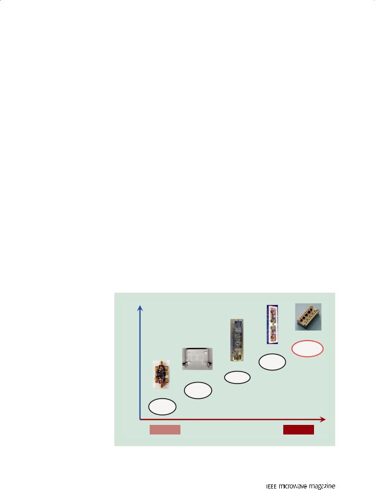
are extensively used for low-pass and bandpass filters thanks to their compact size. However, when high power handling is necessary, special attention must be paid during the design, manufacturing, and tuning of the filters. Therefore, despite its mass and volume, the waveguide is one of the most advisable solutions for implementing microwave components when high power-handling capability is a requirement, even in applications where these features (mass and volume) are critical, such as in the payload of communication satellites. Moreover, waveguide technology benefits from low insertion loss compared to the other microwave technologies.
Several issues should be considered when designing a high-power filter in a rectangular waveguide technology, including multipactor, corona, passive intermodulation, and thermal effects [7]. Considering that one of the most important applications of high-power waveguide filters is their use in satellite payloads, in this article we focus on mutipactor breakdown since it is the most limiting phenomenon when filters are used onboard a space platform. The multipactor effect is a breakdown discharge that occurs in microwave devices operating at high power levels and in vacuum conditions [8], [9]. It is caused by the formation of an electron avalanche originating when free electrons are accelerated by RF fields and collide with the metallic walls of the device with enough energy to release secondary electrons from the surface. If the electrons come into resonance with the field, this process repeats itself until a high electron density is achieved. This results in the disturbance of the sig-
nal, such as distortion, additive noise, high reflections, and, ultimately, a destructive discharge that can damage the device [10]. Therefore, the multipactor effect depends on the following constraints: vacuum condition, frequency of operation in conjunction with the geometry of the component (mainly the minimum mechanical gap), RF voltage applied, and surface characteristics (material, roughness, and so forth).
The concept of high power is imprecise since the terms high or low depend on the application and the specific use of the device. Some may consider hundreds of watts to be high power, whereas others need kilowatts, perhaps at different
June 2020
The waveguide is one of the most advisable solutions for implementing microwave components when high power-handling capability is
a requirement.
frequency ranges or across different technological implementations. However, there are a few elements that escape this ambiguity: for example, high-power filters implemented in planar technology (such as microstrip filters) never achieve the values that can be easily accomplished by waveguide filters, as deduced from Figure 1. In fact, waveguide can be considered the preferred technology for high-power handling.
Our focus in this article is on a future generation of waveguide satellite filters in payloads that need to handle increasing bit rates and numbers of channels; hence, the filters must be prepared to withstand power levels not used in the past and even the sev- eral-kilowatt level of the combined signal. The proposals found in an extensive literature review reveal interesting approaches both in filter designs and in coatings, in some cases for virtually multipactor-free filters. Effects limiting the power handling in waveguide filters are discussed, and we also review some general aspects of paramount importance when high power comes into play, such as thermal control, precise multipactor simulation and measurement, and materials used.
[5]
[4] Waveguide
Dielectric
[3]
[2] Coaxial
Microstrip
Power-Handling Capability |
High Power |
|
47
Authorized licensed use limited to: University of Warwick. Downloaded on May 23,2020 at 03:31:51 UTC from IEEE Xplore. Restrictions apply.

The concept of high power is imprecise since the terms high or low depend on the application and the specific use of the device.
Low-Pass Filter Design
To achieve a low-pass frequency response in rectangular waveguide technology, the classical E-plane corrugated filter is the usual solution as it achieves a wide stopband for the fundamental transverse electric (TE)10 mode [11]. Its topology consists of cascaded highand low-impedance waveguide sections, and its design method has been improved over the last decades to avoid long optimization processes [12]–[15]. Unfortunately, there exists an intrinsic tradeoff between the bandwidth of the stopband and the minimum mechanical gap, which is required in a corrugated filter; this impedes the simultaneous achievement of low-pass corrugated filters with large mechanical gaps and a wide stopband.
To improve the high-power (multipactor) behavior of these devices, the low-pass filter response can be implemented by means of posts with circular shapes that enhance the power handling of the classical structures based on capacitive discontinuities [16] (see Figure 2). Another approach to improving the filter’s immunity to multipactor was proposed in [17], where a device consisting of a classical high-power corrugated low-pass filter is cascaded with a quasi-periodic structure based on the Bragg reflection phenomenon whose period is tuned to reject the undesired intrinsic spurious passbands of the low-pass filter [18]. The technique allows the minimum gap of the corrugated filter to be kept wide, which, along with the smoothness and the large
Figure 2. A low-pass waveguide filter implemented with rounded posts to improve power-handling capability [16].
48
gap of the quasi-periodic structure itself, enables highpower operation in the whole device while the spurious passbands for the TE10 mode are suppressed.
In recent years, a new alternative has arisen that consists of multiple E-plane bandstop elements of sinusoidal profile in a quasi-periodic structure arrangement, where the tuning of the rejected frequencies is achieved through the height of the bandstop elements and not through the period of the structure [Figure 3(a)]. Windowing the quasi-periodic structure height allows the implementation of low-pass filters with deep levels of out-of-band rejection in a wide band, preserving a large mechanical gap [19]. Moreover, this technique was extended to achieve the rejection of not only the fundamental TE10 mode but also all other higher-order modes. This can be essential when the filter is embedded in a system where the power of the signals may be propagating not only in the fundamental mode. Indeed, it can occur, for instance, that the signal is coupled to other modes due to unexpected asymmetries produced during the fabrication process.
These undesired modes can be suppressed by means of a 2D arrangement of E-plane bandstop elements (following a sinusoidal variation both in the transversal and propagation direction of the profile [20]). This structure,
(a)
(b)
Figure 3. Two views of a high-power low-pass filter:
(a) the windowed bandstop elements with smooth profile and (b) the critical area of a filter with a smooth profile showing details of the high concentration of electrons when high-power simulations using SPARK 3D are performed. In filters with smooth profiles, the critical areas are not parallel-plate geometries; therefore, the electrons are easily deviated, reducing the probability of multipactor.
June 2020
Authorized licensed use limited to: University of Warwick. Downloaded on May 23,2020 at 03:31:51 UTC from IEEE Xplore. Restrictions apply.

based on the working principle of classical waffle-iron filters to reject the higher-order modes [21], permits the suppression of wide bands while keeping the high-power behavior. Another possible means to achieve this is by an ad hoc reduction of the filter width [22]. This concept was initially employed in the design of inhomogeneous stepped-impedance corrugated low-pass filters [23] and thus was not intended for high-power applications.
In addition to the mechanical gap, the use of smooth profiles in the aforementioned devices enhances the high-power operation of the filter compared with classical stepped geometries [24], [25]. Indeed, the most critical areas are eliminated since parallel-plate geometries are avoided, and the smoothness facilitates the deviation of the electrons to larger cavities, making the multipactor phenomenon less probable [Figure 3(b)].
Block Filter
(a)
Matching Networks
(b)
(c)
Figure 4. The schematics of a high-power, low-pass filter designed using step-shaped bandstop elements [28]: (a) the block filter used to obtain the required attenuation in the stopband, (b) the matching networks required to achieve the in-band return loss, and (c) the final filter.
June 2020
In addition to their power-handling behavior, smooth profiles are suitable for fabrication by electroforming and thus are a very good option if additive manufacturing techniques are employed.
However, these types of profiles are not suitable for computer numerical control (CNC) milling, which is the method most commonly employed in the aerospace industry, mainly due to cost and lead time. Therefore, these approaches to the design of filters have been recently reconsidered for implementing devices with
(a)
|
|
|
|
(b) |
|
|
0 |
|
|
|
|
|
–20 |
|
|
Measured S11 |
|
|
|
|
Measured S21 |
|
|
|
|
|
|
||
(dB) |
–40 |
|
|
Simulated S11 and S21 |
|
|
|
|
|||
–60 |
|
|
|
|
|
21 |
|
|
|
|
|
|
|
|
|
|
|
S |
|
|
|
|
|
|
–80 |
|
|
|
|
, |
|
|
|
|
|
11 |
|
|
|
|
|
S |
–100 |
|
|
|
|
|
|
|
|
|
|
|
–120 |
|
|
|
|
|
–140 |
|
|
|
|
|
20 |
30 |
40 |
50 |
|
Frequency (GHz)
(c)
Figure 5. A low-pass filter designed following [30]: (a) the fabrication in two halves, (b) the assembled filter, and (c) the frequency response. [Source: European Space Agency Project “Compact High-Power Ka-Band LowPass Filters for Multibeam Satellite Payloads” (customer: TESAT Spacecom); used with permission.]
49
Authorized licensed use limited to: University of Warwick. Downloaded on May 23,2020 at 03:31:51 UTC from IEEE Xplore. Restrictions apply.

stringent specifications (regarding frequency response and high-power-handling capabilities) but also making use of step-shaped bandstop elements (see Figure 4) to ease the fabrication by CNC milling [26]–[29]. In fact, from the thorough analysis performed in [30], it can be concluded that, considering appropriate geometries of the bandstop step-shaped elements, it is possible to fabricate (by CNC milling) low-pass filters addressing a wide stopband and featuring in practice (almost) unlimited power-handling constraints (and consequently no need for costly high-power testing). As an example, a device designed for Ka-band multibeam satellite
TABLE 1. The main features of the filter depicted in Figure 5.
|
Classical |
|
|
Waffle-Iron |
Filter Based |
|
Filter |
on [30] |
|
|
|
Length |
79.6 mm |
55.8 mm |
Longitudinal slots |
12 x 5 |
No slots, easy |
|
|
fabrication |
Minimum gap |
0.65 mm |
2 mm |
Insertion loss |
0.21 dB |
0.11 dB |
(considering silver) |
|
|
Power threshold |
2.1 kW |
19 kW |
(considering silver) |
|
|
Rectangular |
Wedge Shaped |
Propagation Direction
(a)
(b)
Figure 6. The wedge-shaped waveguide: (a) schematics of a rectangular and a wedge-shaped waveguide and (b) a bandpass filter prototype implemented in a wedge-shaped waveguide [38].
50
payloads is shown in Figure 5, and its main features are compared with respect to the classical solution in Table 1. This kind of filter is now accepted by the European satellite industry as a new class of low-pass, highpower filters with high market impact [26].
Bandpass Filter Design
The classical solution to designing a filter with a bandpass frequency response is the inductively coupled rectangular waveguide filter. This filter consists of m/2-long waveguide resonating cavities coupled through inductive irises that act as impedance inverters. The first design method for filters of this kind was based on a lumped-element prototype [31], which provides good results for narrowband filters. Better results were achieved using distributed networks [32], and, additionally, several methods have been proposed in the last decades to achieve devices that are able to operate in a wide frequency range [33]–[36]. In this type of filter, the maximum electromagnetic field levels are achieved in the center of the resonant cavities, where large dimensions can be found and high power-handling operation is consequently easily achievable. Moreover, if larger values are required, alternatives to the rectangular waveguide such as the wedge-shaped waveguide [37] (see Figure 6) can be used to implement the waveguide resonators and increase power operation [38].
However, it is not always possible to fulfill the frequency specifications or the footprint requirements with a classical inductive filter solution, and a vast number of topologies have been published in the last decades to accommodate specific requirements of different applications. Most of them improve the frequency behavior by adding geometries that include small dimensions and/or screws that can be used to tune the frequency response [39] and can thus compromise very-high-power operation. Moreover, dielectric materials can be used to reduce the size of the structures even further. In this case, it is essential to know the main features of the dielectric [40] and use it wisely to maintain or even increase (up to a point) the multipactor level [41], [42]. An example can be seen in Figure 7, where the critical area of a helical resonator filter, typically used for lower power applications, is protected with dielectric material to increase power handling (to values around 100 W). In addition to the multipactor effect, it is also important to take into account the power dissipated inside the dielectric material since it can also limit power handling if the heat generated in the dielectric is not conveniently transferred to the filter housing [43], [44].
Another important issue to consider when designing a bandpass filter is out-of-band performance. Unfortunately, in most bandpass waveguide filters (such as the aforementioned classical inductive devices), the upper stopband is degraded by replicas of the
June 2020
Authorized licensed use limited to: University of Warwick. Downloaded on May 23,2020 at 03:31:51 UTC from IEEE Xplore. Restrictions apply.

passband; hence, it is not possible to achieve a wide, spurious-free response. In [45] and [46], the dimensions of each resonator that composes the filter are modified to shift the replicas up to higher frequencies, improving the out-of-band characteristics of these devices while the fundamental resonance is kept centered around the passband design frequency. These filters, known as inhomogeneous inductive waveguide filters, are able to achieve stopbands free of the first replica.
If a wider spurious-free band is required, low-pass structures can be used to achieve the rejection up to the frequency of interest. An example of a bandpass filter based on a combination of classical low-pass and highpass structures was proposed in [47]. However, as has been previously explained, the use of classical low-pass devices in a rectangular waveguide technology (such as the E-plane corrugated filter) with a wide stopband implies a low minimum mechanical gap and thus low high-power levels. In [48], high-power bandpass filters with a wide stopband are proposed. To achieve the bandpass frequency response, the technique combines a high-pass response obtained by a smooth variation of the width of the rectangular waveguide [49], with the low-pass response accomplished by [19]; this makes it possible to obtain a structure that simultaneously features high power-handling capability and a wide stopband. The combination is done in such a way that the length of the bandpass filter is not increased compared to the low-pass structure. Moreover, the concept has been developed as well in the step-shaped version of these filters and, as is shown in Figure 8, even included as part of a compact diplexer with stringent specifications [50]. This device consists of two bandpass filters that can handle more than 10 kW, even with aluminum as the material for the multipactor simulations.
Filter Cavity
Silver-Plated Helix Rexolite 1422
TNC Connector
Figure 7. A helical resonator filter with dielectric (Rexolite 1422) in the multipactor critical areas to increase the high powerhandling capability [41].
June 2020
A vast number of topologies have been published in the last decades to accommodate specific requirements of different applications.
Multiplexers and Multicarrier Scenario
In a system, a multiplexer is used to combine several narrowband signals into a wideband aggregated signal. This occurs, for example, at the output section of a broadcast communication satellite payload, where the narrowband amplified channel signals are combined to be transmitted through a common antenna [51]. Several configurations can be used to implement a multiplexer, such as hybrid coupled multiplexers, circulator-coupled multiplexers, directional filter multiplexers, and manifold-coupled multiplexers [52].
As is detailed in [53], manifold multiplexers permit the achievement of demanding frequency specifications
Reception Port
(Port 3)
Transmission Port |
(Port 2) |
|
|
|
|
|
|
|
|
|
|
Common Port |
|
|
|
|
|
|
|
(Port 1) |
|
|
|
|
|
|
|
(a) |
|
|
|
|
0 |
|
|
|
|
|
|
|
–20 |
|
|
|
|
|
|
31 |
–40 |
|
|
|
|
|
|
S |
|
|
|
|
|
||
|
|
|
|
|
|
|
|
, |
|
|
|
|
|
|
|
21 |
–60 |
|
|
|
|
|
|
S |
|
|
|
|
|
||
|
|
|
|
|
|
|
|
, |
|
|
|
|
|
|
|
11 |
–80 |
|
|
Measured S11 |
|
|
|
S |
|
|
|
|
|
||
|
|
|
|
Measured S21 |
|
|
|
|
–100 |
|
|
|
|
|
|
|
|
|
Measured S31 |
|
|
|
|
|
|
|
|
|
|
||
|
–1208 |
|
Simulated S11, S21, and S31 |
|
|
||
|
|
|
|
||||
|
12 |
16 |
20 |
||||
Frequency (GHz)
(b)
Figure 8. The compact diplexer: (a) an unassembled diplexer fabricated by CNC milling in aluminum consisting of two bandpass filters and (b) the diplexer frequency response [50].
51
Authorized licensed use limited to: University of Warwick. Downloaded on May 23,2020 at 03:31:51 UTC from IEEE Xplore. Restrictions apply.

In the future, the development of new alloys with good thermal
conductivity, density, and thermal expansion coefficients may help to reduce the effect of extreme temperatures in space.
in terms of insertion loss and group delay response in a compact size. When designing a manifold, it is necessary to consider the effect of the filters included in each channel; this greatly increases the difficulty of implementing manifolds that operate in a large bandwidth or with a large number of channels. Another inherent disadvantage of this configuration is the lack of flexibility, although tunable reactive elements can be introduced along the manifold to obtain a reconfigurable multiplexer [54]. In spite of this design complexity, solutions have been proposed to facilitate the task [55], [56], and the manifold approach is the preferred solution when compact size, low insertion loss, and high power-handling capability are required (see Figure 9).
The estimation of the high power-handling capability of a device operating with a multicarrier signal is more complex than in a single-carrier scenario (addressed in the following sections). As a first approach, the multipactor power threshold can be determined simply as K2 $ Psc, where K is the number of carriers and Psc is the single-carrier breakdown peak power. This calculation assumes that the envelope of the multicarrier signal is that generated when all of the carriers are in phase. This is an unlikely situation (less likely as K increases), and it provides the most pessimistic scenario [57]. Therefore, this conservative approach can lead to unnecessarily oversizing of the design
Figure 9. A manifold-coupled multiplexer with 19 channel filters [53].
52
to avoid risks. The 20-gap-crossing rule [58] is a different approach that can provide a better estimation, although more complex methods have to be used to get accurate values in this intricate situation [57], [59].
Material Considerations
The first commercial satellites implemented waveguide filters and multiplexing networks using Invar [51]. This material features an excellent thermal stability; therefore, it has been widely employed for decades in space applications where RF components must ensure stable behavior over a wide temperature range (typically –10 to +75 °C). However, it also has some disadvantages, such as its mass (in other words, the density of this metal is high, which is an important drawback in applications where this issue is critical). Moreover, Invar’s thermal conductivity, which is also a significant consideration when implementing high-power devices, is not as good as other alternative metals. In high-power applications, resistive heating can be one of the main sources of heat, and so it must be efficiently conducted outside the waveguide cavities to be dissipated. Since this does not easily occur in Invar devices, other materials have also been employed.
Table 2 presents a comparison between different parameters of Invar and aluminum. Although the specific values may depend on the particular alloy employed, it can be clearly inferred that an aluminum device will have reduced weight (by a factor of close to four) when compared with an Invar counterpart. Moreover, aluminum has good thermal conductivity. These properties, along with its easy manufacturability (Invar is prone to warp or break up during machining), make aluminum the preferred solution in many applications.
In demanding applications where stringent specifications are required such as communications satellites, filters fabricated in aluminum are usually silver plated to improve their conductivity and thus reduce insertion loss. Silver also eases high-power operation since it reduces resistive heating, an important source of heat in high-power applications. The heat must be dissipated to avoid the frequency drift producedby the change in the dimensions due to changes in temperature. As the thermal expansion coefficient of aluminum is not as good as Invar’s (see Table 2), several solutions have been implemented to compensate for the temperature variation and reduce or even completely eliminate frequency drift [60]–[62] (see Figure 10). In the future, the development of new alloys with good thermal conductivity, density, and thermal expansion coefficients may help to reduce the effect of extreme temperatures in space [63].
Since it determines the attainable power of RF components in space due to multipactor discharge,
June 2020
Authorized licensed use limited to: University of Warwick. Downloaded on May 23,2020 at 03:31:51 UTC from IEEE Xplore. Restrictions apply.

another material parameter to be considered when manufacturing a device for high-power operation is the secondary emission yield (SEY). As can be seen in Figure 11, this parameter is modeled considering the interaction produced when an electron hits a material: it can be elastically or inelastically backscattered, new electrons can be released (secondary emission effect), or it can be absorbed [64]. Appropriate materials to deal with the multipactor effect must feature a low SEY value while maintaining high conductivity (to reduce insertion loss) and good stability when operating in space conditions. Silver-plated aluminum components can fulfill these requirements since, in addition to the previously mentioned properties, silver exhibits good behavior when its SEY is analyzed [65] and can be easily deposited over an aluminum structure. However, it is important to note that both the specific type of silver and the plating procedure can have a considerable influence on the SEY. In fact, important efforts have been made recently to improve the coatings through micro or nano-structured surfaces, which can reduce or even suppress the multipactor effect without having a significant impact on the RF performance of the devices [66]–[68]. The fabrication method used can also impact this parameter, as explained in [69], where the roughness from additively manufactured surfaces is exploited to reduce the SEY and, hence, to increase the
multipactor threshold.
Multifrequency and multibeam satellites complicate design, simulation, and testing.
Although the parallel-plate model provides an estimation of the threshold input power, in many cases it is too restrictive since the infinite parallel-plate theory results in the worst scenario possible (that is, the lowest breakdown power value). To accurately analyze the multipactor effect, it is essential to know the real electromagnetic field distribution inside the microwave device. Hence, numerical particle-in- cell codes that combine electromagnetic solvers and electron trackers can be used to more precisely calculate the threshold power of the multipactor from input
TABLE 2. A comparison between the material parameters of Invar and aluminum.
|
Invar |
Aluminum |
|
|
|
Coefficient of thermal |
1,6 |
23 |
expansion [ppm/°C] |
|
|
Density [Kg/m3] |
8050 |
2070 |
Thermal conductivity [W/mK] |
10 |
200 |
Multipactor Software Prediction and Measurements
The parallel-plate model is a classical method to calculate the multipactor power threshold in waveguide filters. Developed by the European Space Agency [70], it is based on a set of measurements of parallel plates with different gap sizes. In theory, the model is applied only to parallel-plate geometries of infinite size, but in practice it has been used in both industry and academia with waveguide components of very different sizes and shapes. Still, specific methods to determine the multipactor breakdown voltage in real waveguide components have been developed in [71], [72] and can be used to predict multipactor during the operation of these components.
Invar Plunger Arm
End Wall
Aluminum Filter Body
(a)
(b)
Figure 10. Two Ku-band temperature-compensated devices: (a) a bandpass filter and
(b) a seven-channel output multiplexer [62].
June 2020 |
53 |
Authorized licensed use limited to: University of Warwick. Downloaded on May 23,2020 at 03:31:51 UTC from IEEE Xplore. Restrictions apply.

The relationship between additive manufacturing and high power is an unexplored topic.
parameters such as the frequency of operation, device geometry, and material SEY properties [73]–[75].
To perform multipactor measurements, an experimental setup such as the one described in [76] can be implemented. It must include different local and global detection methods, such as electron probes, a
nulling system of the forward/reverse power at the carrier frequency, or harmonic detection. The electron probe detector is a local method (it is used close to the point of discharge) and relies on the ability of a small, positively charged probe to attract free electrons generated as a result of a discharge. Nulling of the forward/reverse power is a global method. That is, the method indicates whether a discharge is present somewhere in the assembly by superposing the input and reflected signals extracted from the experimental test bed with a directional coupler. Harmonic detection is another reliable global detection method.
CoefficientsSEY |
2 |
|
max |
||
|
||
|
1 |
|
|
0 |
0
Elastic |
Inelastic |
True Secondary |
Reflection |
Backscatter |
Emission |
|
Primary Electron |
|
|
Primary Electron |
|
|
|
Secondary Electrons |
|
|
|
|
|
|
Primary Electron |
|
|
|
|
|
|
|
|
|
(a) |
|
|
|
|
Typical SEY and Electron Energy Contributions |
|
Gold |
2 m |
|||||
|
|
|
|
|
|
Elastically |
|
|
|
|
|
|
|
|
|
Reflected |
|
|
|
|
|
|
|
|
|
Primaries |
|
|
|
|
|
|
|
|
|
Inelastically |
|
|
|
|
|
|
|
|
|
Backscattered |
Silver |
30 m |
|
|
|
|
|
|
|
Primaries |
|
|
|
|
|
|
|
|
|
True |
|
Nickel |
10 m |
|
|
|
|
|
|
Secondaries |
|
|
|
|
|
|
|
|
|
Total SEY |
Aluminum Alloy |
||
|
|
|
|
|
|
Total |
|
Device |
|
|
|
|
|
|
|
Backscattered |
|
|
|
|
|
|
|
|
|
SEY |
|
|
|
E1 |
Emax |
|
|
E2 |
|
|
|
|
|
|
200 |
400 |
600 |
800 |
1,000 |
1,200 |
1,400 |
|
|
|
|
Primary Electron Energy Ep (eV) |
|
|
|
||||
|
|
|
|
(b) |
|
|
|
|
(c) |
Figure 11. The SEY parameter: (a) a schematic of possible interactions between electrons and materials [64], (b) an example of the SEY curve of a material (decomposed in its different contributions) [64], and (c) a schematic diagram of the multilayer antimultipactor coating proposed in [66].
54 |
June 2020 |
Authorized licensed use limited to: University of Warwick. Downloaded on May 23,2020 at 03:31:51 UTC from IEEE Xplore. Restrictions apply.

Nulling |
|
Vacuum Chamber |
||
|
|
|||
System Input/ |
|
Waveguide |
||
Second Harmonic |
Reflected |
DUT |
||
Transformer |
||||
Detection |
DUT Power |
|||
|
Output DUT |
|||
Phase |
|
|
||
|
|
Power |
||
Shifter |
|
|
|
|
|
|
|
Input/Reflected |
|
|
Variable |
Ring Power |
||
|
|
|||
|
Directional |
|
||
|
Coupler |
Signal |
||
|
|
|
Generator |
|
|
(a) |
|
(b) |
|
|
|
|
|
|
Figure 12. A multipactor test bed: (a) a schematic and (b) a test bed including a ring resonator [22]. (Source: European HighPower RF Space Laboratory–European Space Agency and Val Space Consortium; used with permission.)
A multipactor discharge spreads energy over the spectrum, resulting in increased power in the harmonics that can be monitored to detect the presence of a discharge.
If it is necessary to increase the maximum power level available in a test bed to fully characterize devices with large multipactor threshold levels, advanced test beds can be designed [22], [77], [78]. For example, a ring resonator or traveling wave resonator can be assembled following the schematic shown in Figure 12, which shows a ring resonator integrated into a multipactor test bed. Using this setup configuration, it is possible to reinforce the field levels in the critical gap area of the device under test (DUT). To achieve this, three issues must be addressed:
1)The length of the ring must be an integer number of the wavelength at the operation frequency to ensure that the wave that enters into the ring and the one propagating along it are in phase (a phase shifter can be used).
2)The coupling to the ring should be variable to compensate for losses in the ring and to control the magnitude of the wave traveling along it. Therefore, a variable directional coupler, which consists of two directional couplers and a phase shifter, can be used.
3)A method to match out any backward wave should be provided. In this case, two waveguide transformers have been used at the input and output of the DUT.
Conclusions
In satellite communications, increasing capacity means increasing the bit rate and accommodating a larger number of channels; hence, there is a need for the satellite to handle higher combined signal power. New classes of high-power filters are in the spotlight of both academia and industry, and some proposals
have been developed for increasing power handling. Multipaction is the main high-power phenomenon associated with high-power RF satellite payloads. Multifrequency and multibeam satellites complicate design, simulation, and testing. Thermal control is another challenge that engineers of high-power payloads have to face. New aluminum alloys with lower coefficients of thermal expansion may help, especially if parts can be additively manufactured and silver plated. The relationship between additive manufacturing and high power is an unexplored topic where more research is needed, as is the development of specific space-oriented materials that can provide better heat dissipation.
Acknowledgments
This article covers work supported by the Spanish Ministerio de Ciencia, Innovación y Universidades–Agencia Estatal de Investigación under Project TEC2017-85529- C3-2-R (AEI, FEDER-EU).
References
[1]D. Psychogiou and R. Gómez-García, “Symmetrical quasi-reflec- tionless SAW-based bandpass filters with tunable bandwidth,” IEEE Microw. Compon. Lett., vol. 29, no. 7, pp. 447–449, July 2019. doi: 10.1109/LMWC.2019.2918413.
[2]J. Hong and M. J. Lancaster, “Aperture-coupled microstrip openloop resonators and their applications to the design of novel microstrip bandpass filters,” IEEE Trans. Microw. Theory Techn., vol. 47, no. 9, pp. 1848–1855, Sept. 1999. doi: 10.1109/22.788522.
[3]Y. Wang and M. Yu, “True inline cross-coupled coaxial cavity filters,” IEEE Trans. Microw. Theory Techn., vol. 57, no. 12, pp. 2958– 2965, Dec. 2009. doi: 10.1109/TMTT.2009.2034221.
[4]S. Bastioli and R. V. Snyder, “Inline pseudoelliptic TE01d-mode dielectric resonator filters using multiple evanescent modes to selectively bypass orthogonal resonators,” IEEE Trans. Microw. Theory Techn., vol. 60, no. 12, pp. 3988–4001, Dec. 2012. doi: 10.1109/ TMTT.2012.2222659.
[5]V. E. Boria and B. Gimeno, “Waveguide filters for satellites,” IEEE Microw. Mag., vol. 8, no. 5, pp. 60–70, Oct. 2007. doi: 10.1109/ MMM.2007.903649.
June 2020 |
55 |
Authorized licensed use limited to: University of Warwick. Downloaded on May 23,2020 at 03:31:51 UTC from IEEE Xplore. Restrictions apply.