

диафрагмированные волноводные фильтры / 036567f0-eab0-48d7-9ebb-7f1fb79c42c4
.pdfIEEE TRANSACTIONS ON MICROWAVE THEORY AND TECHNIQUES, VOL. 50, NO. 8, AUGUST 2002 |
1969 |
Adaptive Synthesis and Design of Resonator Filters
With Source/Load-Multiresonator Coupling
Smain Amari, Member, IEEE, Uwe Rosenberg, Senior Member, IEEE, and Jens Bornemann, Fellow, IEEE
Abstract— The paper presents a universal and comprehensive synthesis technique of coupled resonator filters with source/load-multiresonator coupling. The approach is based on repeated analyses of a circuit with the desired topology; no similarity transformation is needed. Restrictions imposed by the implementation on the coupling coefficients such as signs and orders of magnitudes are straightforwardly handled within this technique. The technique is then used to synthesize and design filters with full or almost full coupling matrices by selecting, among the infinite number of solutions, the matrix that corresponds to the actual implementation. In such cases, analytical techniques and those based on similarity transformations cannot be used since they provide no mechanism to constrain individual coupling coefficients in order to discriminate between two full coupling matrices, which are both solutions to the synthesis problem. Using the technique described in this paper, a filter designer can extract the coupling matrix of a filter of arbitrary order and topology while enforcing relevant constraints. There is no need to master all the different existing similarity-transformation-based techniques and the topologies to which they are applicable. For the first time, detailed investigations of parasitic coupling effects, for either compensation or utilization, are made possible. The method is applied to the synthesis of a variety of filters, some of which are then designed and built and their response measured.
Index Terms— Bandpass filters, design, dual-mode filters, elliptic filters, resonator filters, synthesis.
I. INTRODUCTION
THE synthesis and design of coupled resonator filters with additional cross-couplings between nonadjacent resonators has been the subject of intense research efforts due to their importance in modern wireless communications systems. Efficient spectrum utilization imposes stringent frequency-se- lectivity requirements, which are commonly met only by those filters with sharp cutoff skirts; additional couplings are often used to generate attenuation poles in the stopband in order to increase the cutoff slope. Naturally, the number of finite transmission zeros and their location in the complex plane determine the performance of the filter, especially its stopband attenuation and group delay. The number of finite transmission
Manuscript received August 4, 2001.
S. Amari is with the Department of Electrical and Computer Engineering, Royal Military College of Canada, Kingston, ON, Canada K7K 7B4 (e-mail: smain.amari@rmc.ca).
U. Rosenberg is with Marconi Communications GmbH, Backnang D-71522, Germany (e-mail: Uwe.Rosenberg@ieee.org).
J. Bornemann is with the Department of Electrical and Computer Engineering, University of Victoria, Victoria, BC, Canada V8W 3P6 (e-mail: jbornema@ece.uvic.ca).
Publisher Item Identifier 10.1109/TMTT.2002.801348.
zeros is directly related to the topology of the coupling network, whereas their location is further affected by the relative signs and magnitudes of the different coupling coefficients.
A survey of the voluminous literature on microwave filters shows that most of the research effort has been focused on filters where the source feeds only one resonator (resonator 1) and the load is connected to only one resonator (resonator  ) [1]–[7]. It is well established that such filters can generate at most

 finite transmission zeros with
  resonators [1]. However, some specifications for filtering structures may be more expediently fulfilled by exploiting additional couplings between the source and the load and the resonators. Indeed, when the source is directly coupled to the load,
  finite transmission zeros can be generated with
  resonators [8], [9]. Despite the attractive features of filters with source/load-multiresonator couplings, their investigation has been reported in only a few papers [10]–[15]. Filters where the source and load are coupled to more than one resonator, but not to each, other were also reported [16]–[18]. The synthesis of canonical filters with source–load coupling can be handled with the technique presented by Bell [19], [20], although no examples were given in these two papers. A slightly more general approach was given by Pfitzenmaier, but again, with no examples [21]. More recently, extraction techniques, which are applicable only to canonical folded structures, were published by Montejo-Garai [22] and Amari [23].
Although the synthesis techniques mentioned above produce a coupling matrix, which fulfills the filter specifications, they eventually rely on similarity transformations to enforce a desired topology [19], [20]. Unfortunately, there is no general and reliable algorithm to generate a coupling matrix with an arbitrarily chosen topology starting from a canonical matrix. When faced with a new topology, a practicing engineer with common experience in dealing with this kind of transformations must rely on the special knowledge of high-level experts in the field. Even when a coupling matrix with the proper topology is obtained, the approach provides no mechanism for enforcing constraints on the individual entries of the coupling matrix. When more than one coupling matrix can satisfy the filter specifications, but only one of these can be realized using the implementation under consideration, it becomes crucial to identify the proper solution, i.e., that matrix whose entries satisfy whatever constraints are imposed by the implementation. The inability of the above-mentioned techniques to strictly enforce an arbitrary topology and constrain the coupling coefficients was the main reason for developing the technique presented in this paper.
The technique is based on the presentation in [24] with proper extension to handle the presence of source/load-multiresonator
0018-9480/02$17.00 © 2002 IEEE

1970 |
IEEE TRANSACTIONS ON MICROWAVE THEORY AND TECHNIQUES, VOL. 50, NO. 8, AUGUST 2002 |
coupling. The coupling coefficients are used as independent variables in minimizing a simple cost function.1
II. FILTERING FUNCTION
The class of filtering functions that are used here are the generalized Chebyshev functions, which can be computed from a simple recursion relation recently given by Amari [24]. The filtering function of order  , i.e.,


 , is related to the transmission coefficient


 by
by
(1)
The ripple level  is related to the minimum in-band return loss
  by
by 


 . The generalized Chebyshev function of order
  is defined by
Fig. 1. Routing and coupling scheme of n coupled resonators with source/load multiresonator coupling. Dark disks: resonators, lighter disks: source and load. Solid lines: direct (main) couplings, dashed lines: bypass couplings.
|
A simple analysis of the network along the lines described in |
||
(2) |
[11] or [19] shows that the loop currents, which are grouped in |
||
a vector |
, are given by a matrix equation of the form |
||
|
|||
where is related to the th transmission zero |
|
by |
|||||||||||||||
|
|
. It can be shown that |
|
|
is a ra- |
||||||||||||
tional function of the form |
|
|
where |
||||||||||||||
the denominator |
|
is given by the product |
|
|
|
||||||||||||
|
[28]. The polynomials |
are related |
|||||||||||||||
by the recursion relation [24] |
|
|
|
||||||||||||||
|
|
|
|
|
|
|
|
|
|
|
|
|
|
|
|
|
|
|
|
|
|
|
|
|
|
|
|
|
|
|
|
|
|
|
|
|
|
|
|
|
|
|
|
|
|
|
|
|
|
|
|
|
|
|
|
|
|
|
|
|
|
|
|
|
|
|
|
|
|
|
|
|
|
|
|
|
|
|
|
|
|
|
|
|
|
|
|
|
|
|
|
|
|
|
|
|
|
|
|
|
|
|
|
|
|
|
|
(3)
The polynomials 


 and
and 


 are given by


 and
and 


 .
.
III. THE MODEL
|
|
|
(4) |
Here, |
is a |
matrix whose only nonzero |
|
entries are |
|
, is similar to the |
|
|
identity matrix, except that |
|
|
[19], and |
is the |
symmetric coupling |
|
matrix. The excitation vector is |
|
. The |
|
low-pass prototype frequency is denoted by |
and is related |
||
to the actual frequency by the standard transformation |
|||
|
, where |
is the center frequency of the |
|
filter and |
is its bandwidth. Both and |
are set to unity |
|
since they act only as scaling parameters [1]. Note that the coupling matrix 

 may have nonzero diagonal elements, which account for differences in the resonant frequencies of the different resonators. The transmission coefficient
 and reflection coefficient

 of the model are given by (load and source resistors
  1)
1)
(5)
and
(6)
The two-resonator model introduced in [11] is extended to the case of  resonators, which are coupled to one another by fre- quency-independent coupling coefficients
 . Both the source and load are coupled to more than one resonator and possibly to each other. The resistive terminations are set to unity. Since the model can be straightforwardly deduced from the discussion in [11], it is not reproduced here. The domain of validity of the model and its scaling properties are well described in [1]. Fig. 1 shows the coupling and routing scheme of a general network of coupled resonators with source/load-multiresonator coupling.
1Note that similar optimization-based approaches were also used for the model described in [1] by Atia et al. [25], Bandler et al. [26], and more recently, by Levy and Petre [27].
The synthesis problem consists in determining the coupling matrix 

 such that a prescribed response is reproduced. The coupling matrix is to have a well-defined topology with coupling coefficients that may be required to satisfy additional constraints that are dictated by the implementation envisaged. A synthesis technique that allows the enforcement of a given topology and constraints on the entries of the coupling matrix, when the source feeds only one resonator and the load is coupled to only one resonator, was recently proposed by Atia et al. [25] and a more comprehensive version by Amari [24]. It is used here after proper extension to handle source–load coupling. The approach determines the coupling matrix by minimizing a suitable cost function where the optimization variables are the nonzero entries of the coupling matrix

 .
.

AMARI et al.: RESONATOR FILTERS WITH SOURCE/LOAD-MULTIRESONATOR COUPLING |
1971 |
IV. COST FUNCTION
The cost function used in this paper is identical to the one given by Amari [24], .i.e.,
(7)
Here, 
 and
and 
 are the zeros and poles of the filtering function


 , respectively. It is assumed that


 has
has  poles and
  zeros. The arguments leading to its derivation can be found in [24] and are not repeated here. Note that the cost function is evaluated at no more than

 frequency points for a filter of order
  .
.
V. GRADIENT OF COST FUNCTION
In this paper, we use a gradient-based optimization technique where the gradient of the cost function is computed exactly and from a single analysis of the model.
The gradient of the cost function given in (7) is determined from the gradient of the reflection and transmission coefficients. Following the discussion in [24], it is straightforward to establish the following results:
(8a)
(8b)
(8c)
(8d)
Here, the topology matrix 

 of the network is defined by


 if
if 


 and
and 


 if
if 


 . The topology of the network can be specified beforehand and will be enforced at
each step in the optimization. The matrix 

 is given in (4).
VI. COMPUTATION OF GROUP DELAY
The group delay of the synthesized filter can be determined from the transmission coefficient directly without first computing its phase and without finite differences. Again, a simple extension of the formulation in [24] leads to
(9)
where 


 stands for the imaginary part of
  . Note that the sum runs from

 to
to 


 , while that in [24] runs from

 to
to 

 since the latter does not involve source–load coupling and both the source and load are coupled to only one resonator each.
VII. RESULTS
The synthesis technique described in this paper was applied to filters of varied orders and topologies. A sample of these are discussed here.
The first example (filter 1) is a third-order filter with three transmission zeros at finite frequencies. The center frequency of the filter is 26.453 GHz, its bandwidth is 41 MHz, and its maximum in-band return loss is 26 dB. The transmission zeros are located at 


 GHz,
GHz, 


 GHz, and


 GHz. To implement a total of three finite transmission zeros using three resonators, it is necessary to couple the source to the load directly. Although the total number of finite transmission zeros is then determined, their locations in the complex plane depend on the remaining details of the topology. To accommodate the planned implementation of this filter, a coupling matrix of the following form is sought:
(10)
Note that the filter is symmetric, although its response is not. The initial guess for the optimization corresponds to setting all couplings to zero, except 
 and
and 
 , which are set to 1.0 and 0.9, respectively. These values are chosen to guarantee a signal path between input and output. We also used the starting point


 and
and 


 and all the remaining entries in the coupling matrix set to zero with no noticeable difference in the convergence of the minimization process. (A “better” initial guess corresponds to using the Chebyshev solution for a filter of the same order and minimum in-band return loss, but with the three transmission zeros removed to infinity.) After optimization, the obtained coupling matrix is
(11)
The transmission and reflection coefficients of the filter, as computed directly from the filtering function, are shown in Fig. 2. The presence of the three transmission zeros, as well as the specified minimum in-band return loss, are evident. Also plotted are the transmission and reflection coefficients obtained directly from the coupling matrix in (11), computed according to (5) and (6). The difference between the two results is not visible, thereby illustrating the accuracy of the synthesis technique.

1972 |
IEEE TRANSACTIONS ON MICROWAVE THEORY AND TECHNIQUES, VOL. 50, NO. 8, AUGUST 2002 |
Fig. 2. Transmission and reflection coefficients of filter 1 (synthesized), as obtained from the coupling matrix in (11) and the filtering function. The two cannot be distinguished.
Fig. 3. Group delay (normalized) for filter 1 as obtained from (9) and by differentiating the phase of S
 . The two cannot be distinguished.
The group delay of the filter was also computed from (9) and is shown in Fig. 3. We also calculated the group delay from the derivative of the phase of the transmission coefficient and obtained identical results. We should mention that Fig. 3 shows
the normalized group delay, which is related to the actual group delay by a simple transformation [21].
The synthesized filter has been realized by a symmetrical cavity configuration, which is folded in the  -plane and op-

AMARI et al.: RESONATOR FILTERS WITH SOURCE/LOAD-MULTIRESONATOR COUPLING |
1973 |
Fig. 5. Photograph of the realized filter (filter 1).
Fig. 4. Layout and dimensions (in millimeters) of filter 1.
erated with 

 resonance modes (cf. Fig. 4). Cavities 1 and 3 exhibit a common broad wall, which contains the inter-cavity iris 1–3 needed for all bypass couplings. There are irises at the center of the respective other broad wall of these cavities for interfacing with WR34 waveguides (representing source and load, respectively), i.e., the ports are located at opposite sides of the overall structure. One broad wall of cavity 2 faces one of the narrow walls of the adjacent cavities 1 and 3 to allow the realization of the main couplings (


 ) between the cavities by irises within their respective common walls. Due to this symmetrical structure, there are four bypass couplings that have been considered by the synthesis of the coupling matrix.
First, coupling |
is realized directly by the inter-cavity iris |
||
1–3. Second, |
is performed by the input irises, the nonres- |
||
onating |
mode of cavity 1, and also the inter-cavity iris |
||
1–3. Third, |
corresponds to the second one, but |
||
to the output direction. Fourth, |
uses the input and output |
||
irises, inter-cavity iris 1–3, and the nonresonating |
cavity |
||
modes of cavities 1 and 3. Consequently, the present design makes use of the parasitic effects presented in [16]. It should be noted that the transformation properties of overmoded cavities, as introduced in [29], must be considered carefully for the realization of this type of filters.
Since the bypass couplings partly use the same discontinuities, (e.g., inter-cavity iris 1–3) control of the individual couplings is obtained by accurate determination of the geometry (width and height) and location (1) of the dedicated irises. For the present filter, it was sufficient to consider these parameters for the inter-cavity iris 1–3 only.
The filter structure has been optimized using a mode-matching based computer-aided design (CAD) tool to fit the specifications—and, finally, it has been realized by computer numerically controlled milling techniques. Owing to the very narrow bandwidth (  0.2%), a little tuning is necessary to account for the manufacturing tolerances. Fig. 5 shows a photograph of the realized filter.
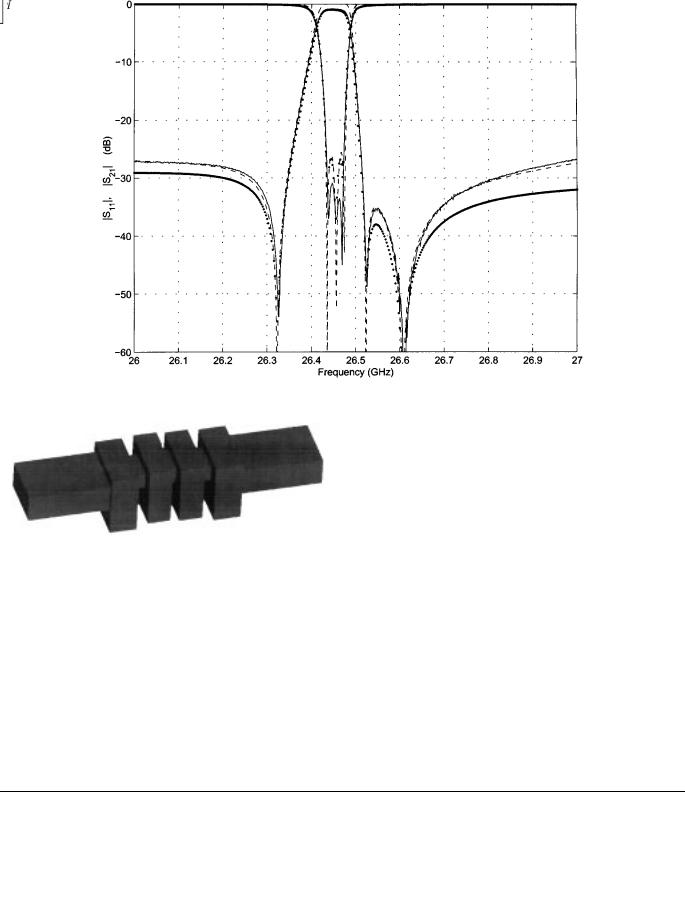
Fig. 6 depicts the comparison of the filter response from the synthesis (dashed line), computer field theoretic simulation (dotted line), and measurement (solid line). All results agree
well and validate the presented method. The measured in-band insertion loss can be well accounted for by the present synthesis method using the realizable unloaded  factor of about 6000 (cf. Fig. 6), corresponding to a
  -efficiency of approximately 75%.
The next example (filter 2) was chosen to better illustrate the necessity of constraining the individual coupling coefficients to fit the implementation; it is no longer sufficient to simply generate a coupling matrix with the proper topology and whose response fulfills the specifications. The filter specifications are met by a fourth-order filter with four transmission zeros in the lower stopband. The center frequency is 


 GHz, the bandwidth is 450 MHz, the in-band return loss is 26 dB, and the transmission zeros are located at


 GHz,
GHz, 


 GHz,
GHz, 


 GHz, and


 GHz.
GHz.
The implementation of the filter involves a full coupling matrix where each resonator is coupled to all the remaining ones and the source and load are coupled to each other and to each of the four resonators. Bypass couplings are realized through the idea of utilizing parasitic couplings [16].
The structure of this special in-line cavity filter is depicted in Fig. 7. It is based on single-mode 


 -mode resonances. The inter-cavity irises are located in the broad walls of the cavities, which couple mainly magnetically. The waveguide interface ports directly face the respective broad wall of the first and fourth cavities with an offset from the center for the realization of the assigned coupling magnitudes and signs. Moreover, cross-couplings are realized by electrical bypasses through the irises and

 (nonresonating) cavity modes. Consequently, the satisfaction of a desired filter response needs proper control of all main and cross-couplings, which is performed by optimization of all iris dimensions (cross section, length, and offsets in regards to the respective cavities) and the cavity dimensions as well. Hence, all couplings, including the source–load one, may be realized. However, the magnitude of the cross-coupling coefficients decreases with the number of bypassed discontinuities (irises and cavities).
It is well established that the response of a given full coupling matrix is invariant under any similarity transformation that does not modify the input and output [19]. It should be obvious that there exist an infinite number of solutions to the synthesis problem examined in this example. However, most of these solutions cannot be implemented using the structure in Fig. 7. Indeed, from our experience with this kind of cross-couplings (utilized parasitic), the magnitude of a bypass coupling decreases
1974 |
IEEE TRANSACTIONS ON MICROWAVE THEORY AND TECHNIQUES, VOL. 50, NO. 8, AUGUST 2002 |
Fig. 6. Transmission coefficient of filter 1. Solid line: measured. Dashed line: simulated. Dotted line: synthesized.
Fig. 7. Structure used for filter 2.
by roughly an order of magnitude for each bypassed cavity. For example, 
 ,
, 
 , and
, and 
 must satisfy the inequalities


 .
.
The application of the synthesis technique yielded the coupling matrix, shown in (12), at the bottom of this page, which satisfies both the specifications and the constraints.
Note that other coupling matrices, which yield the same response, were also obtained, but were rejected because their entries do not fit the constraints imposed by the special in-line implementation (Fig. 7).
Starting from this coupling matrix, a filter was designed and simulated using a mode-matching based CAD tool. The insertion and return loss versus frequency are shown in Fig. 8 as the solid lines. It is in excellent agreement with the synthesized response of the coupling matrix given in (5) and (6) (cf. dotted line in Fig. 8). To further validate these results, the filter was analyzed with the CST Microwave Studio (finite-integral based). The CST results, which are shown as the dashed line in Fig. 8, are in good agreement with those of the coupled integral-equa- tions technique (CIET), which has been extensively tested (cf. [30] and [31]).
The third example (filter 3) concerns an asymmetric five-pole filter response exhibiting four transmission zeros above the passband (see Fig. 9). A compact realization of this filter uses one triple-mode cavity and one dual-mode cavity, as shown in Fig. 10.
The input port of the filter is located at one top wall of the triple mode cavity—a convenient offset iris design allows simultaneous couplings of the dedicated 


 and
and 


mode with the interfacing 

 waveguide mode [15]. The other top wall of the triple mode cavity is facing the dual mode
(12)

AMARI et al.: RESONATOR FILTERS WITH SOURCE/LOAD-MULTIRESONATOR COUPLING |
1975 |
Fig. 8. Response of filter 2. Solid line: CIET. Dashed line: CST. Dotted line: prototype.
Fig. 9. Transmission and reflection coefficients of filter 3.
one, which is short circuited at one end. Possible inter-cavity
couplings can be performed between |
identically polarized |
|
modes, as well as between the |
modes of the |
|
dual-mode cavity and the |
mode of the triple mode |
|
one by offset irises [33]. However, the latter ones must consider a simultaneous coupling of the respective 


 modes within both cavities [33]. The output port is located at the circumference of the triple mode cavity—a slot iris is aligned

1976
Fig. 10. Structure for the realization of filter 3.
IEEE TRANSACTIONS ON MICROWAVE THEORY AND TECHNIQUES, VOL. 50, NO. 8, AUGUST 2002
Using these entries for the straightforward optimization with the introduced method yields the coupling matrix, shown in (14), at the bottom of this page, which exactly satisfies the desired response with the inherent design restrictions of the triple/dual-mode cavity configuration. Note that the main coupling 
 becomes zero and resonance 3 is only coupled to resonance 4 (


 ), i.e., the complete energy is transferred by bypass couplings
 ,
, 
 ,
, 
 , and
, and 
 . The principle iris designs for the required couplings are indicated in the sketch in Fig. 10.
VIII. ISSUE OF CONVERGENCE
along the circumference (situated at nearly maximum magnetic
field components of the |
and vanishing -field |
|
components of the |
modes) to allow coupling of the |
|
mode only with the interfacing |
waveguide |
|
mode.2 As is well known, properly located screws in the cavity walls (not shown in the sketch) allow individual frequency adjustment of the dedicated resonance modes and provide the assigned couplings between the modes of the same cavity.
The allocation of the resonance modes to the filter circuits and the coupling possibilities of the desired triple/dual-mode realization mentioned above yields the feasible entries of the coupling matrix, shown in (13), at the bottom of this page.
Additional constraints are imposed on the magnitudes of cou-
plings, namely, |
and |
relating to proper |
|
offset iris designs of inter-cavity couplings between the |
|
||
modes of the dual-mode cavity with the respective |
and |
||
modes of the triple mode one. |
|
|
|
2Note that an offset of the iris in the cavity axial direction may also provide the possibility of TE

 -mode couplings to the “load” interface port, but would yield increased design effort and, thus, has not been further considered.
A perennial issue that optimization-based techniques face is the thorny problem of convergence. Obviously, the fact that the method converged for all cases examined does not constitute a proof that convergence is always guaranteed. Perhaps a reassuring point in this regard lies in the observation that the minimum of the cost function for an exact synthesis is known beforehand and is equal to zero. As long as a minimum value of zero is reached, the resulting coupling matrix is guaranteed to satisfy the original specifications. If the minimum reached is nonzero, the solution can be either rejected or examined further to decide whether it provides an acceptable approximation to the synthesis problem. Naturally, the method will not converge to zero when the chosen topology cannot generate the desired response regardless of the actual values of the coupling coefficients.
It is possible to devise complex algorithms to deal with convergence within the method described here. A simple scheme corresponds to starting from the Chebyshev solution, which is known analytically [32], and then move the finite transmission zeros gradually from infinity (a large normalized value, say, 40) to their final location. The solution from one step is then used
(13)
(14)

AMARI et al.: RESONATOR FILTERS WITH SOURCE/LOAD-MULTIRESONATOR COUPLING |
1977 |
as the initial guess in the next step where the zeros are moved further closer to their final locations. Fortunately, in all cases examined, this laborious scheme has not been necessary.
IX. CONCLUSIONS
A systematic and universal method of synthesis of coupled resonator filters with source/load-multiresonator coupling has been presented. The method eliminates the need for similarity transformations and enforces the desired topology directly. Constraints dictated by the implementation, in regards to orders of magnitude and signs, can be enforced within the technique. This is a major advantage over existing extraction-followed-by-rota- tions techniques, which cannot constrain the entries of the coupling matrix. The entries of the coupling matrix are used as independent variables in a gradient-based minimization technique, where a cost function is evaluated at no more than 

 frequency points for a filter of order
  . The gradient of the cost function is determined analytically from a single analysis of the circuit. The method has been applied to filters of varied degrees and symmetries and has yielded excellent results. Example filters have been synthesized, designed, simulated, and measured.
REFERENCES
[1]A. E. Atia and A. E. Williams, “New type of waveguide bandpass filters for satellite transponders,” COMSAT Tech. Rev., vol. 1, no. 1, pp. 21–43, 1971.
[2]A. E. Williams, “A four-cavity elliptic waveguide filter,” IEEE Trans. Microwave Theory Tech., vol. MTT-18, pp. 1109–1114, Dec. 1970.
[3]R. J. Cameron, “General prototype network synthesis methods for microwave filters,” ESA J., vol. 6, pp. 193–206, 1982.
[4], “General coupling matrix synthesis methods for Chebyshev filtering functions,” IEEE Trans. Microwave Theory Tech., vol. 47, pp. 433–442, Apr. 1999.
[5]R. J. Cameron and J. D. Rhodes, “Asymmetric realizations of dual-mode bandpass filters,” IEEE Trans. Microwave Theory Tech., vol. MTT-29, pp. 51–58, Jan. 1981.
[6]IEEE Trans. Microwave Theory Tech. (Special Issue), vol. MTT-30, Sept. 1982.
[7]IEEE Trans. Microwave Theory Tech. (Special Issue), vol. 42, July 1994.
[8]S. Amari and J. Bornemann, “Maximum number of finite transmission zeros of coupled resonator filters with source/load-multi-resonator coupling and a given topology,” in Proc. Asia–Pacific Microwave Conf. , Sydney, 2000, pp. 1175–1177.
[9]P. Röschmann, “Compact YIG bandpass filter with finite pole frequencies for applications in microwave integrated circuits,” IEEE Trans. Microwave Theory Tech., vol. MTT-29, pp. 52–57, Jan. 1973.
[16], “Consideration of parasitic bypass couplings in overmoded cavity filter designs,” IEEE Trans. Microwave Theory Tech., vol. 42,
pp.1301–1306, July 1994.
[17]J. F. Liang and W. D. Blair, “High- Q TE01 mode DR filters for PCS wireless base stations,” IEEE Trans. Microwave Theory Tech, vol. 46,
pp.2493–2500, Dec. 1998.
[18]I. C. Hunter, J. D. Rhodes, and V. Dassonville, “Dual-mode filters with conductor-loaded dielectric resonators,” IEEE Trans. Microwave Theory Tech., vol. 47, pp. 2304–2311, Dec. 1999.
[19]H. C. Bell, Jr., “Canonical lowpass prototype network for symmetric coupled-resonator bandpass filters,” Electron. Lett., vol. 10, no. 13, pp. 265–266, June 1974.
[20], “Canonical asymmetric coupled-resonator filters,” IEEE Trans. Microwave Theory Tech., vol. MTT-30, pp. 1333–1340, Sept. 1982.
[21]G. Pfitzenmaier, “Synthesis and realization of narrow-band canonical microwave bandpass filters exhibiting linear phase and transmission zeros,” IEEE Trans. Microwave Theory Tech., vol. MTT-30, pp. 1300–1311, Sept. 1982.
[22]J. R. Montejo-Garai, “Synthesis of N-even order symmetric filters with N transmission zeros by means of source–load cross coupling,” Electron. Lett., vol. 36, no. 3, pp. 232–233, Feb. 2000.
[23]S. Amari, “Direct synthesis of folded symmetric resonator filters with source–load coupling,” IEEE Microwave Wireless Comp. Lett., vol. 11,
pp.264–266, June 2001.
[24], “Synthesis of cross-coupled resonator filters using an analytical gradient-based optimization technique,” IEEE Trans. Microwave Theory Tech., vol. 48, pp. 1559–1564, Sept. 2000.
[25]W. A. Atia, K. A. Zaki, and A. E. Atia, “Synthesis of general topology multiple coupled resonator filters by optimization,” in MTT-S Int. Microwave Symp. Dig., 1998, pp. 821–824.
[26]J. W. Bandler, S. H. Chen, and S. Daijavad, “Exact sensitivity analysis for the optimization of coupled cavity filters,” J. Circuit Theory Applicat., vol. 31, pp. 63–77, 1986.
[27]R. Levy and P. Petre, “Design of CT and CQ filters using approximation and optimization,” in IEEE MTT-S Int. Microwave Symp. Dig., Phoenix, AZ, May 2001, pp. 1467–1470.
[28]R. J. Cameron, “Fast generation of Chebychev filter prototypes with asymmetrically prescribed transmission zeros,” ESA J., vol. 6, pp. 83–95, 1982.
[29]U. Rosenberg, “New ‘planar’ waveguide cavity elliptic function filters,” in Proc 25th Eur. Microwave Conf., Bologna, Italy, Sept. 1995, pp. 524–527.
[30]S. Amari, J. Bornemann, and R. Vahldieck, “Accurate analysis of scattering from multiple waveguide discontinuities using the coupled-inte- gral-equations technique,” J. Electromagn. Waves Applicat., vol. 10, pp. 1623–1644, 1996.
[31]J. Bornemann, U. Rosenberg, S. Amari, and R. Vahldieck, “Edge-con- ditioned vector basis functions for the analysis and optimization of rectangular waveguide dual-mode filters,” in IEEE MTT-S Int. Microwave Symp. Dig., Anaheim, CA, June 1999, pp. 1695–1698.
[32]G. L. Matthaei, L. Young, and E. M. T. Jones, Microwave Filters, Impedance Matching Networks and Coupling Structures. Norwood, MA: Artech House, 1980.
[33]U. Rosenberg and D. Wolk, “Filter design using in-line triple-mode cavities and novel iris couplings,” IEEE Trans. Microwave Theory Tech., vol. 37, pp. 2011–2019, Dec. 1989.
[10]K. A. Zaki, C. Chen, and A. E. Atia, “Modeling of coupling probes in dual mode cavities,” in IEEE MTT-S Int. Symp. Dig., New York, 1988, pp. 515–518.
[11]S. Amari and J. Bornemann, “CIET-analysis and design of folded asymmetric H-plane waveguide filters with source–load coupling,” in Proc. 30th Eur. Microwave Conf., vol. 2, Paris, 2000, pp. 270–273.
[12]E. Ofli, R. Vahldieck, and S. Amari, “Analysis and design of mass-pro- Smain Amari (M’98) received the DES degree in physics and electronics from
ducible cross coupled, folded E-plane filters,” in IEEE MTT-S Int. Microwave Symp. Dig., Phoenix, AZ, 2001, pp. 1775–1778.
[13]I. Awai, A. C. Kundu, and T. Yamashita, “Equivalent circuit representation and explanation of attenuation poles of a dual-mode dielectric-res- onator bandpass filter,” IEEE Trans. Microwave Theory Tech., vol. 46, pp. 2159–2163, Dec. 1998.
[14]L. H. Hsieh and K. Chang, “Dual-mode elliptic function bandpass filter using one single patch resonator without coupling gaps,” Electron. Lett., vol. 36, no. 24, pp. 2022–2023, Nov. 2000.
[15]U. Rosenberg and W. Hägele, “Advanced multimode cavity filter design using source/load-resonance circuit cross couplings,” IEEE Trans. Microwave Guided Wave Lett., vol. 2, pp. 508–510, Dec. 1992.
Constantine University, Constantine, Algeria, in 1985, and the Masters degree in electrical engineering and the Ph.D. in physics from Washington University, St. Louis, MO, in 1989 and 1994, respectively.
From 1994 to 2000, he was with the Department of Electrical and Computer Engineering, University of Victoria, Victoria, BC, Canada. From 1997 to 1999, he was a Visiting Scientist with the Swiss Federal Institute of Technology, Zurich, Switzerland, and a Visiting Professor in Summer 2001. Since November 2000, he has been with the Department of Electrical and Computer Engineering, Royal Military College of Canada, Kingston, ON, Canada, where he is currently an Associate Professor. He is interested in numerical analysis, numerical techniques in electromagnetics, applied physics, applied mathematics, and quantum many-particle systems.

1978 |
IEEE TRANSACTIONS ON MICROWAVE THEORY AND TECHNIQUES, VOL. 50, NO. 8, AUGUST 2002 |
Uwe Rosenberg (M’90–SM’93) received the Dipl. Ing. degree (first-class honors) in electrical engineering (telecommunication technique) from the Fachhochschule der Deutschen Bundespost, Dieburg, Germany, in 1982.
From 1982 to 1983, he was with Hydro Therm, Dieburg, Germany, where he was involved with the design and development of automatic safety and heating control circuits. From 1983 to 1985, he was with the Technische Hochschule Darmstadt, Darmstadt, Germany, where he was involved with
the design and development of experimental installations and software components for microcomputer control systems. In 1985, he joined the Space Division, ANT Nachrichtentechnik GmbH (now Tesat-Spacecom GmbH & Company KG), Backnang, Germany, where he was engaged in research and development on microwave filters, multiplexers, and passive subsystems for communications satellites. Since 1989, he has been Head of the Research and Development Laboratory for Passive Microwave Components and Subsystems, Marconi Communications GmbH (formerly Bosch Telecom GmbH, Public Networks Division), Backnang, Germany, where he has been responsible for research and development of integrated waveguide transceiver circuitries, channel branching networks (multiplexers), antenna feed and waveguide (feeder) systems for trunk and access radio applications, mobile base-stations, large Earth stations, and communications satellites. He co-authored Waveguide Components for Antenna Feed Systems: Theory and CAD (Norwood, MA: Artech House, 1993). He has also authored or co-authored over 40 technical papers. He holds 36 microwave design patents
Mr. Rosenberg is a member of Verband der Elektrotechnik Elektronik Informationstechnik (VDE), Informationstechnische Gesellschaft (ITG), and Verein Deutscher Ingenieure (VDI). He is a senior member of the IEEE Microwave Theory and Techniques Society (IEEE MTT-S) and the IEEE Antenna and Propagation Society (IEEE AP-S).
Jens Bornemann (M’87–SM’90–F’02) received the Dipl.-Ing. and Dr.-Ing. degrees in electrical engineering from the University of Bremen, Bremen, Germany, in 1980 and 1984, respectively.
From 1984 to 1985, he was a Consulting Engineer. In 1985, he joined the University of Bremen, as an Assistant Professor. Since April 1988, he has been with the Department of Electrical and Computer Engineering, University of Victoria, Victoria, BC, Canada, where he became a Professor in 1992. From 1992 to 1995, he was a Fellow of the British
Columbia Advanced Systems Institute. In 1996, he was a Visiting Scientist at Spar Aerospace Limited (now EMS Technologies Inc.), Ste-Anne-de-Bellevue, QC, Canada, and a Visiting Professor with the Microwave Department, University of Ulm, Ulm, Germany. Since 1997, he has been a Co-Director of the Center for Advanced Materials and Related Technology (CAMTEC), University of Victoria. He co-authored Waveguide Components for Antenna Feed Systems. Theory and Design (Norwood, MA: Artech House, 1993) and has authored/co-authored over 170 technical papers. His research activities include microwave/millimeter-wave components and systems design, and problems involving electromagnetic-field theory in integrated circuits, waveguide feed networks, and radiating structures. He serves on the Editorial Advisory Board of the International Journal of Numerical Modeling.
Dr. Bornemann is a Registered Professional Engineer in the Province of British Columbia, Canada. He is a member of the IEEE Microwave Theory and Techniques Society (IEEE MTT-S) and the IEEE Antennas and Propagation Society (IEEE AP-S). From 1999 to 2002, he was an associate editor for the IEEE TRANSACTIONS ON MICROWAVE THEORY AND TECHNIQUES in the area of microwave modeling and CAD. He serves on the Technical Program Committee (TPC) of the IEEE MTT-S International Microwave Symposium. He was a corecipient of the 1983 A. F. Bulgin Premium of the Institution of Electronic and Radio Engineers