

диафрагмированные волноводные фильтры / 48964033-d479-432c-8a14-43e82c5ac25b
.pdfSpecial Issue on Metamaterials EBG
Dual resonator 1-D EBG antenna with slot array feed for improved radiation bandwidth
A.R. Weily, K.P. Esselle, T.S. Bird and B.C. Sanders
Abstract: A one-dimensional (1-D) electromagnetic bandgap (EBG) resonator antenna with both high gain and wide radiation bandwidth is described. The use of dual resonators in combination with an array of sources leads to a dramatic increase in the radiation bandwidth of the antenna. The effect of the dual resonators is to increase the bandwidth over which the EBG material acts as a spatial filter, while the array feed increases both the directivity and radiation bandwidth. Theoretical results for a prototype designed to operate at Ku-band are presented and shown to be in good agreement with measured results. The effect of increasing the number of array elements on directivity and radiation bandwidth is examined, and the improvements of the proposed configuration compared with a classical 1-D EBG resonator antenna with single source is presented.
1 Introduction
Electromagnetic bandgap (EBG) and frequency selective surface (FSS) resonator antennas have attracted considerable interest recently due to their highly directional radiation properties. In these antennas, an EBG material or FSS is typically placed a half-wavelength above a metallic ground plane containing either a single patch, slot or waveguide aperture feed antenna. The EBG material used to create the resonator antenna may be periodic in one-dimension (1-D) [1–4], two-dimensions (2-D) [5–8], or three-dimensions [9, 10]. Alternatively, an FSS material may be used to create a partially reflective surface [11], or combined with an artificial magnetic conductor (AMC) to further reduce the profile of the antenna [12]. In each of these configurations, the EBG material or FSS in combination with the ground plane (or AMC) creates a resonator that has an angle-dependent coupling to free space. This coupling, and the properties of the feed antenna, creates highly directive radiation patterns for the overall structure. Unfortunately, the radiation bandwidth for these types of antennas is quite low, which limits their usefulness. For 1-D EBG resonator antennas, it has been shown that there is a relationship between the maximum gain value and the gain bandwidth that depends on the properties of the EBG material [13] or FSS. Maximum gain can be traded for gain bandwidth and vice versa by modifying the quality factor of the resonator through the properties of the EBG material (number of layers and dielectric contrast). It has also been shown that the radiation bandwidth of a
# The Institution of Engineering and Technology 2007
doi:10.1049/iet-map:20050314
Paper first received 30th November 2005 and in revised form 16th May 2006
A.R. Weily, K.P. Esselle and T.S. Bird are with the Department of Electronics, Macquarie University, Sydney, NSW 2109, Australia
TS. Bird is also with CSIRO ICT Centre, PO Box 76, Epping 1710 NSW, Australia
B.C. Sanders is with the Institute for Quantum Information Science, University of Calgary, Alberta T2N 1N4, Canada and the Australian Centre of Excellence for Quantum Computer Technolgy, Macquarie University, Sydney, NSW 2109, Australia
E-mail: aweily@ics..mq.edu.au
resonator antenna may be increased by using an array of microstrip patches instead of a single source [13]. Here we describe a method for further increasing the radiation bandwidth by means of a dual-resonator 1-D EBG material in combination with an array of sources (see Fig. 1).
2 Dual resonator 1-D EBG structure
To explain the bandwidth improvement of the proposed antenna, we compare normal incidence transmission through a multiple resonator configuration with that of a single resonator structure. The 1-D EBG material, made from a stack of quarter wavelength slabs, creates a Bragg mirror for normally incident waves through an interference phenomenon. The larger the number of layers and the larger the dielectric contrast between the slabs, the better the reflective qualities of the mirror. If we create a single defect or resonator in the stack as shown in Fig. 2a, a very narrow transmission band is formed at the wavelength corresponding to the approximate width of the resonator. This transmission band has been calculated using dielectric multilayer theory [4] and is shown in Fig. 3. The dielectric materials used for the structure in Fig. 2 are Rogers TMM3
(1r ¼ 3.3, tan d ¼ 0.002) |
and TMM4 |
(1r ¼ 4.4, |
tan |
d ¼ 0.002). To create an |
antenna from |
the single |
1-D |
EBG resonator, a metallic plate containing a source is placed at the symmetry plane of the structure as described by The`venot et al.[2]. To increase the transmission bandwidth, we modify the classical 1-D EBG structure of Fig. 2a to create a 3-pole spatial filter as shown in Fig. 2b. In this configuration, the width of the air gaps and the permittivity value of the outer slabs have been optimised to centre the transmission band on 12.1 GHz and to give a maximally flat passband transfer function. The permittivity of the outer slabs controls the external coupling factor of the filter, while the spacing of the TMM4 slabs between the resonators can be used to control interresonator coupling. Transmission through the structure is also presented in Fig. 3, which shows that through the use of multiple resonators the 23 dB transmission bandwidth
198 |
IET Microw. Antennas Propag., 2007, 1, (1), pp. 198–203 |

TMM3
12.7mm (Resonator 2)
TMM4 |
5.5mm |
12.5mm (Resonator 1)
|
z |
Metallic Ground Plane |
|
|
|
y |
|
x |
|
|
4x8 Slot Array |
Fig. 1 Cutaway drawing of the dual resonator 1-D EBG antenna with slot array feed
Each TMM sheet is 3.18 mm thick
is increased from 0.54 to 9.05% (i.e. the quality factor decreases from 185 to 11).
3 Antenna design
Our antenna prototype has been designed to operate in Kuband and to specifically cover frequencies from 11.7 to 12.5 GHz that are typically used in receive terminals for direct broadcast satellite applications. The design aims for the antenna are low side lobes, good impedance matching, reasonably constant gain and low cross-polarisation levels over the specified operating bandwidth.
The dual resonator antenna design is based on the structure of Fig. 2b with a metallic plate placed at the symmetry plane. To further increase both the radiation bandwidth and directivity of the antenna, an array of 4 8 stripline slots are placed on the metallic plate to couple energy to the resonators. In our experience, the use of slots instead of microstrip patches makes it easier to tune the input impedance of the antenna, a task that is further complicated when considering an array due to the mutual coupling effects between elements. The other advantage of the stripline-fed slots is that the array feed network is located below the ground plane containing the slots and has a minimal effect on the radiation pattern of the antenna. For microstrip patch arrays with the feed network located in the same plane as the patches, coupling between the feed network and radiating elements can potentially cause serious cross-polarisation degradation.
Normally Incident |
|
Normally Incident |
|
|
|||||
Plane Wave |
|
|
|
Plane Wave |
|
|
|
||
|
|
|
|
|
|
||||
|
|
|
|
|
|
|
|
|
|
|
|
|
|
|
|
|
|
|
3.18 |
|
|
|
|
3.18 |
|
|
|
TMM3 |
|
6.4 |
|
|
TMM4 |
12.7 |
|
|
|
|
|
|
|
|
3.18 |
|
|
|
|
||
|
|
|
|
|
|||||
|
|
|
|
|
|
|
|
|
|
|
|
|
TMM4 |
|
|
|
|
3.18 |
|
6.4 |
|
|
|
|
5.5 |
|
|
TMM4 |
|
|
|
|
|
|
|
|
|
||
|
|
|
|
3.18 |
|
|
|
|
3.18 |
|
|
|
TMM4 |
|
|
|
TMM4 |
||
24 |
|
|
Symmetry |
25 |
|
|
Symmetry |
||
|
|
|
|
||||||
|
|
|
Plane |
|
|
|
Plane |
||
|
|
|
|
|
|
|
|
||
|
|
|
|
3.18 |
|
|
|
|
3.18 |
|
|
|
|
|
|
|
|
||
|
|
|
TMM4 |
5.5 |
|
|
TMM4 |
||
6.4 |
|
|
|
|
|
|
|
3.18 |
|
|
|
|
|
|
|||||
|
|
|
|
3.18 |
|
|
|
TMM4 |
|
6.4 |
|
|
TMM4 |
12.7 |
|
|
|
|
|
|
|
|
3.18 |
|
|
|
|
||
|
|
|
|
|
|||||
|
|
|
|
|
|
|
|
|
|
|
|
|
TMM4 |
|
|
|
|
3.18 |
|
|
|
|
|
|
|
|
|
TMM3 |
|
|
|
|
a |
|
|
|
|
b |
|
Fig. 2 Configuration and dimensions
aClassical single resonator 1-D EBG structure
bMultiple resonator 1-D EBG Structure
All dimensions are in millimetres
|
0 |
|
|
|
|
|
|
|
−5 |
|
|
|
|
|
|
(dB) |
−10 |
|
|
|
|
|
|
|
|
|
|
|
|
|
|
Transmission |
−15 |
|
|
|
|
|
|
−20 |
|
|
|
|
|
|
|
−25 |
|
|
|
|
|
|
|
|
|
|
|
|
|
|
|
|
–30 |
|
|
|
Multiple Resonator |
|
|
|
|
|
|
|
|
||
|
|
|
|
|
Single Resonator |
|
|
|
−35 |
4 |
8 |
12 |
16 |
20 |
24 |
|
0 |
||||||
|
|
|
|
Frequency (GHz) |
|
|
|
Fig. 3 Normal incidence transmission as a function of frequency through the configurations shown in Fig. 2
The final configuration of the dual resonator 1-D EBG antenna is shown in Fig. 1. The stripline feed network is made from two layers of 0.787 mm thick Rogers RT/ Duroid 5880 substrate. It is used to distribute energy to an array of 4 8 slots, where the dimensions of the slots are
10.84 mm by 3.2 mm. The slot |
spacing |
corresponds |
to |
half a free-space wavelength |
in the |
x-direction |
at |
12.1 GHz, and a full wavelength in the y-direction. The array of slots is approximately equivalent to a 4 4 array of microstrip patches with a wavelength spacing between elements in both the x- and y-directions (since a patch antenna may be modelled by two slot antennas). Located 12.5 mm above the slot array is the first TMM4 sheet with dimensions 152 152 3.18 mm. This is followed by a
5.5 mm |
air gap, an identical TMM4 sheet, a |
12.7 mm |
air gap, |
and finally a TMM3 sheet with |
size of |
152 152 3.18 mm. The dielectric sheets are supported above the slot array using M3 nylon bolts and spacers, and the rigidity of the stripline feed layers has been increased by attaching it to a 6 mm thick aluminium backing plate. The feed network for the antenna, depicted in Fig. 4, is a typical corporate feed structure designed to supply an equal amplitude and phase excitation to each of the slots. It consists of 31 individual power dividers arranged to form a 32-way power divider network. For each power divider, a quarter-wavelength low-impedance section is used to match an input 50 V stripline to two 50 V output striplines.
The design of the dual resonator antenna was completed using in-house finite-difference time-domain (FDTD) codes that implement Berenger’s perfectly matched layer absorbing boundary conditions [14]. Simulations were completed on a two processor NEC SX5 vector supercomputer with 12 Gb of shared memory and a maximum speed of 16 Gflops. Each complete simulation of the dual resonator antenna (with 4 8 slot feed) used 12 000 time steps of the FDTD algorithm, required 8685 Mb of memory and took 6.25 h to compute. A comparison of the measured and computed reflection coefficient for the final prototype is given in Fig. 5. The measured impedance bandwidth extends from 11.511 to 12.816 GHz, thus covering the objective bandwidth of 11.7 to 12.5 GHz. Radiation patterns and gain of the antenna were measured using the NSI-700S-50 spherical nearfield system located at CSIRO. The measured H- and E-plane radiation patterns for the antenna are compared with FDTD results in Figs. 6 and 7, respectively. The frequencies shown are 11.7, 12.1 and
IET Microw. Antennas Propag., Vol. 1, No. 1, February 2007 |
199 |

Fig. 4 Feed network for the 4 8 slot array of the dual resonator 1-D EBG antenna
Slots have been superimposed on the stripline feed network to show their relative position
12.5 GHz, which correspond to the lower, centre and upper values, respectively, of the objective bandwidth. These plots highlight the directive nature of the antenna and show reasonable agreement between measurement and theory. Discrepancies between measurement and simulation, such as the increased asymmetry in the E-plane radiation patterns, may be attributed to manufacturing tolerances of the feed network and slot array, which has caused the excitation amplitudes of the array feed to become slightly nonuniform. The measured and computed half power beamwidths and gain of the antenna are listed in Table 1. The measured and computed gain and directivity of the antenna are plotted in Fig. 8. Measured maximum gain is 22.7 dBi at 12 GHz, and the gain bandwidth (where gain is less than 3 dB below the maximum value) extends from 11.251 to 12.835 GHz, or 13.2%. This represents a dramatic increase in gain bandwidth when compared with a single resonator 1-D EBG antenna with a single source, which
|
0 |
|
|
|
|
|
|
−5 |
|
|
|
|
|
(dB) |
−10 |
|
|
|
|
|
|
|
|
|
|
|
|
Reflection |
−15 |
|
|
|
|
|
|
|
|
|
|
|
|
|
−20 |
|
|
|
|
|
|
|
|
|
|
Measured |
|
|
−25 |
|
|
|
FDTD |
|
|
11 |
12 |
13 |
14 |
15 |
|
|
10 |
|||||
|
|
|
Frequency (GHz) |
|
|
|
Fig. 5 Measured against computed reflection coefficient
|
0 |
|
|
|
|
Measured |
|
|
|
|
|
|
|
|
|
|
|
|
|
|
|
FDTD |
|
|
−10 |
|
|
|
|
|
|
(dB) |
−20 |
|
|
|
|
|
|
Power |
|
|
|
|
|
|
|
|
|
|
|
|
|
|
|
Relative |
−30 |
|
|
|
|
|
|
|
|
|
|
|
|
|
|
|
−40 |
|
|
|
|
|
|
|
−50 |
−60 |
−30 |
0 |
30 |
60 |
90 |
|
−90 |
||||||
|
|
|
|
Angle (degrees) |
|
|
|
|
|
|
|
a |
|
|
|
|
0 |
|
|
|
|
Measured |
|
|
|
|
|
|
|
|
|
|
|
|
|
|
|
FDTD |
|
|
−10 |
|
|
|
|
|
|
(dB) |
−20 |
|
|
|
|
|
|
Power |
|
|
|
|
|
|
|
|
|
|
|
|
|
|
|
Relative |
−30 |
|
|
|
|
|
|
|
|
|
|
|
|
|
|
|
−40 |
|
|
|
|
|
|
|
−50 |
−60 |
−30 |
0 |
30 |
60 |
90 |
|
−90 |
||||||
|
|
|
|
Angle (degrees) |
|
|
|
|
|
|
|
b |
|
|
|
|
0 |
|
|
|
|
Measured |
|
|
|
|
|
|
|
|
|
|
|
|
|
|
|
FDTD |
|
|
−10 |
|
|
|
|
|
|
(dB) |
−20 |
|
|
|
|
|
|
Power |
|
|
|
|
|
|
|
|
|
|
|
|
|
|
|
Relative |
−30 |
|
|
|
|
|
|
|
|
|
|
|
|
|
|
|
−40 |
|
|
|
|
|
|
|
−50 |
−60 |
−30 |
0 |
30 |
60 |
90 |
|
−90 |
||||||
|
|
|
|
Angle (degrees) |
|
|
|
c
Fig. 6 Measured and computed H-plane radiation patterns
a11.7 GHz
b12.1 GHz
c12.5 GHz
has an approximate bandwidth of 1.5%. Over the design bandwidth of 11.7 to 12.5 GHz, the variation in gain is within 0.8 dB of the maximum value, and the boresight cross-polarisation levels remain lower than 234 dB (typically much lower). The measured results for directivity, gain, mismatch, radiation efficiency and antenna efficiency over the design bandwidth are compared in Table 2. The radiation efficiency given in the table includes the dielectric
200 |
IET Microw. Antennas Propag., Vol. 1, No. 1, February 2007 |

|
0 |
|
|
|
|
Measured |
|
|
|
|
|
|
|
|
|
|
|
|
|
|
|
FDTD |
|
|
−10 |
|
|
|
|
|
|
(dB) |
−20 |
|
|
|
|
|
|
Power |
|
|
|
|
|
|
|
|
|
|
|
|
|
|
|
Relative |
−30 |
|
|
|
|
|
|
|
|
|
|
|
|
|
|
|
−40 |
|
|
|
|
|
|
|
−50 |
−60 |
−30 |
0 |
30 |
60 |
90 |
|
−90 |
||||||
|
|
|
|
Angle (degrees) |
|
|
|
|
|
|
|
a |
|
|
|
|
0 |
|
|
|
|
Measured |
|
|
|
|
|
|
|
|
|
|
|
|
|
|
|
FDTD |
|
|
−10 |
|
|
|
|
|
|
(dB) |
−20 |
|
|
|
|
|
|
Power |
|
|
|
|
|
|
|
|
|
|
|
|
|
|
|
Relative |
−30 |
|
|
|
|
|
|
|
|
|
|
|
|
|
|
|
−40 |
|
|
|
|
|
|
|
−50 |
−60 |
−30 |
0 |
30 |
60 |
90 |
|
−90 |
||||||
|
|
|
|
Angle (degrees) |
|
|
|
|
|
|
|
b |
|
|
|
|
0 |
|
|
|
|
Measured |
|
|
|
|
|
|
|
|
|
|
|
|
|
|
|
FDTD |
|
|
−10 |
|
|
|
|
|
|
(dB) |
−20 |
|
|
|
|
|
|
Power |
|
|
|
|
|
|
|
|
|
|
|
|
|
|
|
Relative |
−30 |
|
|
|
|
|
|
|
|
|
|
|
|
|
|
|
−40 |
|
|
|
|
|
|
|
−50 |
−60 |
−30 |
0 |
30 |
60 |
90 |
|
−90 |
||||||
|
|
|
|
Angle (degrees) |
|
|
|
c
Fig. 7 Measured and computed E-plane radiation patterns
a11.7 GHz
b12.1 GHz
c12.5 GHz
|
25 |
|
|
|
|
|
|
|
|
(dBi) |
23 |
|
|
|
|
|
|
|
|
|
|
|
|
|
|
|
|
|
|
Gain & Directivity |
21 |
|
|
|
|
|
|
|
|
19 |
|
|
Directivity (Measured) |
|
|
|
|||
|
|
|
|
|
|
||||
|
|
|
|
Directivity (FDTD) |
|
|
|
||
|
|
|
|
Gain (Measured) |
|
|
|
||
|
|
|
|
Gain (FDTD) |
|
|
|
|
|
|
17 |
11.25 |
11.5 |
11.75 |
12 |
12.25 |
12.5 |
12.75 |
13 |
|
11 |
||||||||
Frequency (GHz)
Fig. 8 Measured and computed directivity and gain
loss of the TMM and 5880 substrates, the conductor loss of the antenna and the array feed network losses. The measured aperture efficiency of the antenna at 11.7, 12.1 and 12.5 GHz is 57, 53 and 45%, respectively. A photograph of the prototype dual resonator 1-D EBG antenna with slot array feed is shown in Fig. 9.
A dual resonator antenna with an array of 8 16 slots has also been modelled to examine the effect of increasing the number of sources on the maximum directivity and radiation bandwidth. To accommodate the extra slots, the aperture size of the antenna is increased, and the feed network modified. Apart from these changes, all other parameters such as slot separation, slot size, material properties and separation between TMM sheets remain the same as the previous configuration. The size of the TMM3 and TMM4 sheets used is 271 271 3.18 mm, and the feed network uses 127 power dividers to distribute energy to 128 slots in the ground plane of the antenna. The maximum directivity for this configuration occurs at 11.3 GHz and is 29 dBi. From array theory, we would expect a 6 dB increase in directivity after 4-fold increase in the number of array elements, however due to the effect of the 1-D EBG material, the increase is only 4.6 dB higher than the 4 8 array feed. The computed E- and H-plane radiation patterns at 11.3 GHz obtained with FDTD are plotted in Fig. 10 and confirm the highly directive nature of the antenna. To investigate the effect of the EBG material on the directivity of the array, we have modelled the 8 16 slot array without any EBG material. The directivity increase due to the EBG material varies as a function of frequency. At 11.3 GHz, the directivity increase is 4.6 dBi, and at 12.5 GHz it is 7 dBi. This variation with frequency is due to the grating lobes in the H-plane of the array, whose level increases with frequency. The EBG material suppresses these grating lobes and thus has the greatest effect on directivity where the grating lobe levels are highest (i.e. at higher frequencies).
To examine the radiation bandwidth improvement of the dual resonator antenna with array feed over a classical 1-D
Table 1: Comparison of the measured and computed HPBW and gain
Frequency, GHz |
E-plane HPBW |
|
H-plane HPBW |
Gain, dBi |
|
|
|
Measured |
Computed |
Measured |
Computed |
Measured |
Computed |
11.7 |
13.28 |
11.08 |
10.28 |
10.48 |
22.16 |
22.90 |
12.1 |
11.88 |
11.88 |
10.48 |
10.78 |
22.48 |
22.30 |
12.5 |
12.78 |
10.48 |
10.18 |
10.38 |
21.90 |
22.40 |
IET Microw. Antennas Propag., Vol. 1, No. 1, February 2007 |
201 |
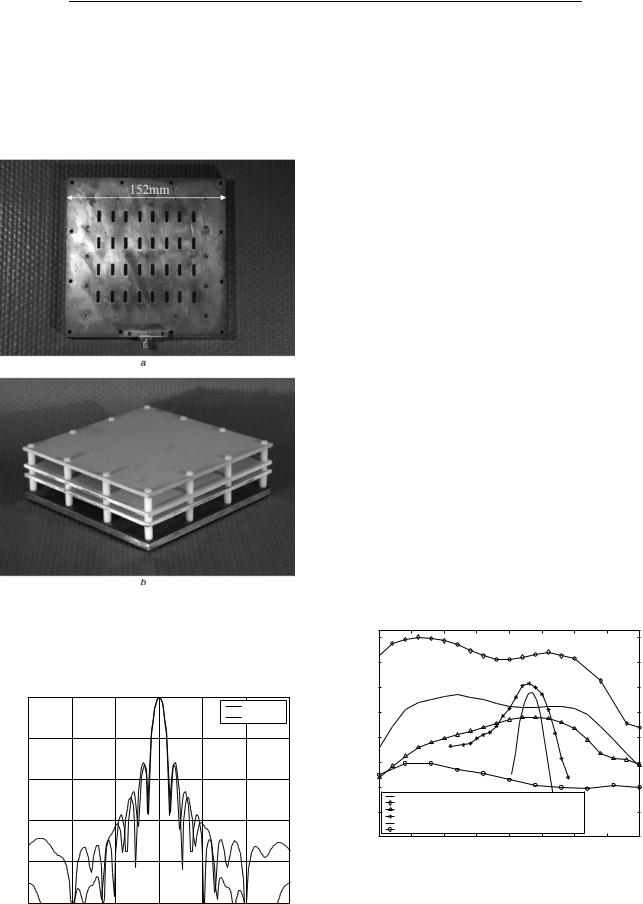
Table 2: Measured directivity, gain, mismatch, radiation efficiency and antenna efficiency
Frequency, |
Directivity, |
Gain, dBi |
Mismatch, |
Radiation |
Antenna |
GHz |
dBi |
|
dB |
Efficiency, dB |
efficiency, % |
|
|
|
|
|
|
11.7 |
24.02 |
22.16 |
20.31 |
21.55 |
65 |
12.1 |
24.02 |
22.48 |
20.08 |
21.46 |
70 |
12.5 |
23.53 |
21.90 |
20.17 |
21.46 |
69 |
|
|
|
|
|
|
Fig. 9 Photographs of the prototype antenna
a 4 8 slot array
b Dual resonator EBG antenna with slot array feed
|
0 |
|
|
|
|
E−plane |
|
|
|
|
|
|
|
|
|
|
|
|
|
|
|
H−plane |
|
|
−10 |
|
|
|
|
|
|
(dB) |
−20 |
|
|
|
|
|
|
Power |
|
|
|
|
|
|
|
|
|
|
|
|
|
|
|
Relative |
−30 |
|
|
|
|
|
|
|
|
|
|
|
|
|
|
|
−40 |
|
|
|
|
|
|
|
−50 |
|
|
|
|
|
|
|
−90 |
−60 |
−30 |
0 |
30 |
60 |
90 |
|
|
|
|
Angle (degrees) |
|
|
|
Fig. 10 Computed E- and H-plane radiation patterns of the dual resonator 1-D EBG antennas with 8 16 element slot array feed at 11.3 GHz
EBG resonator antenna, we compare the computed radiation bandwidth of several configurations in Fig. 11. The parameters of the classical structure are those reported in the work of Weily et al. [4] (similar to Fig. 2a with a metal plate placed at the symmetry plane) and consists of three quarter wave thick TMM4 layers placed a half wavelength above a ground plane and fed by a single microstrip patch antenna. The computed radiation bandwidth for the classical structure with a single source extends from 12.072 to 12.259 GHz (or 1.5%), while for the dual resonator antenna with a 4 8 element slot array feed it extends from 11.071 to 12.745 GHz (or 14.1%). When we quadruple the number of slots of the dual resonator antenna using an 8 16 element array feed, the radiation bandwidth extends from 10.68 to 12.644 GHz (or 16.8%). Hence increasing the number of elements while using the same element spacing in the array feed gives a slight increase in radiation bandwidth.
We also compare dual resonator and single resonator EBG antennas with the same resonator quality factor, where both antennas are fed by an identical 4 8 element slot array. To obtain the same quality factor of 11 in a single resonator structure, we use two sheets of RT/ Duroid 5880 substrates (1r ¼ 2.2, tan d ¼ 0.0009) with dimensions 152 152 4.18 mm. The quality factor was obtained from the 23 dB transmission bandwidth of the symmetrical single resonator multilayer structure (similar to Fig. 2a except with two sheets of Duroid placed on either side of the symmetry plane). To create the antenna,
|
29 |
|
|
|
|
|
|
|
|
|
27 |
|
|
|
|
|
|
|
|
|
25 |
|
|
|
|
|
|
|
|
(dBi) |
23 |
|
|
|
|
|
|
|
|
|
|
|
|
|
|
|
|
|
|
Directivity |
21 |
|
|
|
|
|
|
|
|
19 |
|
|
|
|
|
|
|
|
|
|
|
|
|
|
|
|
|
|
|
|
17 |
Dual Resonator EBG Antenna (4x8 |
Slot Array Feed) |
|
|
|
|||
|
|
|
|
|
|||||
|
|
Dual Resonator EBG Antenna (8x16 Slot Array Feed) |
|
|
|
||||
|
15 |
Single Resonator EBG Antenna (4x8 Slot Array Feed, 2 Duroid Sheets) |
|
|
|||||
|
Single Resonator EBG Antenna (4x8 Slot Array Feed, 3 TMM4 Sheets) |
|
|
||||||
|
|
Single Resonator EBG Antenna (Single Patch Feed, 3 TMM4 Sheets) |
|
|
|||||
|
|
4x8 Slot Array (no EBG) |
|
|
|
|
|
|
|
|
11 |
11.25 |
11.5 |
11.75 |
12 |
12.25 |
12.5 |
12.75 |
13 |
|
|
|
|
Frequency (GHz) |
|
|
|
||
Fig. 11 Comparison of the theoretical directivity for different configurations of 1-D EBG antennas (dual resonator with 4 8 slot array feed, dual resonator with 8 16 slot array feed, single resonator with 4 8 slot array feed and two Duroid sheets EBG, single resonator with 4 8 slot array feed and three TMM4 sheets EBG, classical single resonator with single patch feed and three TMM4 sheets EBG) and a slot array with no EBG superstrate
202 |
IET Microw. Antennas Propag., Vol. 1, No. 1, February 2007 |
the first Duroid sheet is placed 12.4 mm above the slot array, and the air gap between the two Duroid sheets is 6.2 mm, giving the EBG a centre frequency of 12.1 GHz. The radiation bandwidth of this antenna, shown in Fig. 11, extends from 11.215 to 12.725 GHz (or 12.6%) and the peak directivity is 22.6 dBi. We conclude that the dual resonator structure has a wider radiation bandwidth and the peak directivity is 1.8 dBi higher than the single resonator configuration with the same quality factor. The dual resonator EBG antenna has further advantage that the directivity is flatter over the radiation bandwidth, and the sidelobes of the radiation patterns are lower.
Also included in Fig. 11 for comparison is a single resonator 1-D EBG antenna (three sheets of TMM4) with a 4 8 element slot array feed, with a radiation bandwidth of 3.3% and the directivity of the 4 8 element array feed without any type of EBG superstrate. The radiation bandwidth improvement of the dual resonators with 4 8 element array feed is more than nine times that of the classical structure, whereas for the dual resonators with 8 16 element array it is 11 times. The use of a single resonator (three sheets of TMM4) in combination with a 4 8 element array feed gives an improvement of two times compared to the classical structure. We also note that the increase in the antenna height of the dual resonator structure above the metallic ground plane, compared to the classical three layer structure, is only 5.9 mm (or 17%).
Future work will examine further improvements in the radiation bandwidth of resonator antennas with array feeds by increasing the number of 1-D EBG resonators to greater than two. Such multiple resonator structures will further increase the band of frequencies over which the EBG material acts like a spatial filter, but will most likely provide a lower directivity due to their lower quality factor. Thus, the directivity improvement compared to a standard array will be less dramatic. A multiple resonator approach will also have the disadvantage of increasing the height of the antenna, compared to dual and classical 1-D EBG resonator configurations. However, for many applications, the increased bandwidth and improved radiation patterns (compared to a standard array antenna) should outweigh these disadvantages.
4 Conclusion
A high gain antenna has been developed from a dual resonator 1-D EBG structure for Ku-band direct broadcast satellite applications. A significant increase in radiation bandwidth has been demonstrated through the combination of a dual resonator structure and a 4 8 slot array feed. The measured gain bandwidth for the Ku-band prototype was 13.2% and the maximum gain was 22.7 dBi at 12 GHz. An improvement in radiation bandwidth of almost one order of magnitude was achieved at the expense of only a small increase in antenna height, compared to a classical 1-D EBG resonator antenna with a single source. The measured sidelobes and boresight cross-polarisation levels also remain quite low, and the prototype demonstrated nearly constant gain over a prescribed design bandwidth. By quadrupling the number of array elements, it was
shown that a theoretical directivity of 29 dBi is achieved. The increased radiation bandwidth of the dual resonator antenna has the further advantage of easing fabrication and material tolerances typically required in classical high gain 1-D EBG resonator structures, where the operating frequency is very sensitive to small variations in the antenna dimensions and dielectric constant of materials.
5 Acknowledgments
This work was supported by an ARC Linkage Postdoctoral Fellowship (LC0348615). The spherical nearfield system was funded by an ARC LIEF grant (LE0453911). B.C.S. acknowledges financial support from the Alberta informatics Circle of Research Excellence (iCORE) fund and the Canadian Institute for Advanced Research. The authors would like to thank the Australian Centre for Advanced Computing and Communications (AC3) for providing access to high-performance computing facilities.
6References
1Yang, H.Y., and Alexopoulos, N.G.: ‘Gain enhancement methods for printed circuit antennas through multiple superstrates’, IEEE Trans. Antennas Propag., 1987, 35, (7), pp. 860–863
2The`venot, M., Cheype, C., Reineix, A., and Jecko, B.: ‘Directive photonic bandgap antennas’, IEEE Trans. Microw. Theory Tech., 1999, 47, (11), pp. 2115–2122
3Serier, C., Cheype, C., Chantalat, R., The`venot, M., Mone´die`re, T., Reineix, A., and Jecko, B.: ‘1-D photonic bandgap resonator antenna’, Microw. Opt. Technol. Lett., 2001, 29, (5), pp. 312–315
4Weily, A.R., Esselle, K.P., Sanders, B.C., and Bird, T.S.: ‘High-gain 1D EBG resonator antenna’, Microwave Opt. Technol. Lett., 2005, 47, (2), pp. 107–114
5The`venot, M., Denis, M.S., Reineix, A., and Jecko, B.: ‘Design of a new photonic cover to increase antenna directivity’, Microw. Opt. Technol. Lett., 1999, 22, (2), pp. 136–139
6Qiu, M., and He, S.: ‘High directivity patch antenna with both photonic bandgap substrate and photonic bangap cover’, Microw. Opt. Technol. Lett., 2001, 30, (1), pp. 41–44
7Cheype, C., Serier, C., The`venot, M., Mone´die`re, T., Reineix, A., and Jecko, B.: ‘An electromagnetic bandgap resonator antenna’, IEEE Trans. Antennas Propag., 2002, 50, (9), pp. 1285–1290
8Lee, Y.J., Yeo, J., Mittra, R., and Park, W.S.: ‘Application of electromagnetic bandgap (EBG) superstrates with controllable defects for a class of patch antennas as spatial angular filters’, IEEE Trans. Antennas Propag., 2005, 53, (1), pp. 224–235
9Biswas, R., Ozbay, E., Temelkuran, B., Bayindir, M., Sigalas, M.M., and Ho, K.M.: ‘Exceptionally directional sources with photonic-bandgap crystals’, J. Opt. Soc. Am. B, 2001, 18, (11), pp. 1684–1689
10Weily, A.R., Horvath, L., Esselle, K.P., Sanders, B.C., and Bird, T.S.: ‘A planar resonator antenna based on a woodpile EBG material’, IEEE Trans. Antennas Propag., 2005, 53, (1), pp. 216–223
11Feresidis, A.P., and Vardaxoglou, J.C.: ‘High gain planar antenna using optimized partially reflective surfaces’, IEE Proc. Microw. Antennas Propag., 2001, 148, (6), pp. 345–350
12Feresidis, A.P., Goussetis, G., Wang, S., and Vardaxoglou, J.C.: ‘Artificial magnetic conductor surfaces and their application to low-profile high-gain planar antennas’, IEEE Trans. Antennas Propag., 2005, 53, (1), pp. 209–215
13Leger, L., Monediere, T., and Jecko, B.: ‘Enhancement of gain and radiation bandwidth for a planar 1-D EBG antenna’, IEEE Microw. Wirel. Compon. Lett., 2005, 15, (9), pp. 573–575
14Taflove, A., and Hagness, S.C.: ‘Computational electrodynamics: the finite-difference time-domain method’ (Artech House, Boston MA, 2000, 2nd edn.)
IET Microw. Antennas Propag., Vol. 1, No. 1, February 2007 |
203 |