

диафрагмированные волноводные фильтры / a5d962ca-48c9-43e9-8705-cd8a45a58613
.pdfUniaxial Discontinuities Analysis by a New Multimodal Variational Method––Application to Filter Design
De´ sire´ Lilonga-Boyenga, Junwu Tao, Taˆ n Hoa Vuong
ENSEEIHT, 2, rue Charles Camichel, 31071 Toulouse, France
Received 29 September 2005; accepted 19 June 2006
ABSTRACT: A new mulitimodal varational formulation (NMVF) is presented for the characterization of cascaded discontinuities in microwave components by using a formal admittance operator of the complete structure. The admittance operator is constructed by using all higher-order modes in intermediate waveguides, so that the convergence study versus the number of modes will no longer be needed, contrary to classical modal decomposition methods. This formulation will theoretically lead to increased accuracy for the overall S parameters. To validate this new approach, a step-discontinuity is analyzed and an evanescent mode bandpass filter is designed.
Keywords: passive microwave components; multiple uniaxial discontinuity; multimodal variational formulation; microwave filter
1. INTRODUCTION
The development of modern communication systems over the last few years required the realization of increasingly compact and powerful equipment and working at increasingly high frequencies. Various methods of electromagnetic modeling of circuits in millimeter waves and microwaves were developed; thanks to the availability of more powerful means of calculation. The current tendency comprises the use of the CAD simulation tools to reduce the computational time and manufacturing cost of the circuits [1]. However, the complexity of the circuits and the process of optimization, often necessary during the design stage, increase the computing time. Since the 1980s, several methods of uniaxial discontinuity analysis in
Correspondence to: J.W. Tao; e-mail: tao@enseeiht.fr DOI 10.1002/mmce.20200
Published online 8 December 2006 in Wiley InterScience (www.interscience.wiley.com).
passive microwave circuits have been developed such as the generalized S matrix [2] and the multimodal variational method (MVM) [3]. For the individual discontinuity, the field expansion into the eigenmodes of each guiding structure has been considered in both techniques, in a straightforward way in [2] and by the definition of a formal admittance operator in [3]. The overall S matrix is then obtained by cascading the generalized S matrix of each individual discontinuity, allowing the analysis and design of a number of passive microwave components [3, 4].
As in most modal decomposition techniques, an important factor for obtaining accurate results is the choice of the size of the generalized S matrix for each discontinuity, which is dependent on the truncation of eigenmode basis. In the MVM case, this choice leads to the determination of an accessible mode number [3]. Thus, the convergence study of parameters as function of accessible number in different waveguides of the structure becomes necessary to obtain the required accuracy. To avoid this conver-
VC 2006 Wiley Periodicals, Inc.
77

78 Lilonga-Boyenga, Tao, and Vuong
Figure 1. Uniaxial N-discontinuity structure.
gence study, a new multimodal variational formulation (NMVF) is presented in this paper in which a new formal admittance operator will be defined for the complete structure by using all higher-order modes in the intermediate guiding structures. We will outline this rigorous analysis of multiple discontinuities in which the S-parameters of the entire structure is deduced from its overall impedance matrix.
2. NEW MULTIMODAL VARIATIONAL FORMULATION
2A. Formal Complete Structure
Admittance Operator
A uniaxial N discontinuity structure is considered as shown in Figure 1. At the ith interface between the waveguides i and i þ 1, the surface current density is related to the magnetic fields by
~ |
~ðiÞ |
~ðiþ1Þ |
ðziÞÞ |
! |
ð |
Þ |
JdðziÞ ¼ ðHt |
ðziÞ Ht |
n |
||||
|
|
|
|
1 |
|
|
~ðiÞ ~ðiþ1Þ
where Ht and Ht represent transverse magnetic
!
fields in each waveguide. n is the unity vector of propagation direction z.
The use of the eigenmode basis in each waveguide and their orthogonality property leads to a formal relation between the current density and the transverse electric field at each discontinuity plane:
~ |
ðz1 |
^ |
~ |
|
^ |
~ |
Þ |
|
Jd |
Þ ¼ Y11 |
Etðz1Þ þ Y12 Etðz2 |
|
|||||
~ |
|
^ |
|
~ |
|
^ |
~ |
|
JdðzN |
Þ ¼ YN 1;N EtðzN 1 |
Þ þ YN;N EtðzN Þ |
ð2Þ |
|||||
~ |
|
^ |
|
~ |
|
^ ~ |
||
Jdðzi |
Þ ¼ Yi 1;i |
Etðzi 1 |
Þ þ Yi;i EtðziÞ |
|
||||
|
|
^ |
~ |
|
Þ; i ¼ |
2; :::; N 1 |
|
|
|
|
þ Yi;iþ1 Etðziþ1 |
|
|||||
|
|
~ |
~ |
|
|
|
|
|
By denoting Jd and Et, the surface current density
vector and the tangential electric field vector of the overall structure interfaces respectively, one can write in a matrix form:
~ |
^ ~ |
ð3Þ |
Jd ¼ Y Et |
||
with ^ the admittance matrix operator of the com-
Y
plete structure, defined by
^ |
|
X |
1 |
|
|
|
^ð1Þ |
|
|
X |
|
2d |
|
|
^ð2Þ |
|
|
|
|
||||||||
Y11 ¼ |
|
|
ynð Þðz1Þ Yn þ |
|
¼ |
ymð Þðl1Þ Ym |
|
|
|
|
|||||||||||||||||
|
|
|
¼ |
|
|
|
|
|
|
|
|
|
|
m |
|
|
|
|
|
|
|
|
|
|
|
||
|
^ |
n |
1 |
|
|
|
|
^ðiþ1Þ |
|
1 |
|
|
|
|
|
|
|
|
^ðiÞ |
|
|||||||
|
X |
id |
|
|
|
|
|
X |
i 1;d |
|
|
|
|
|
|
||||||||||||
|
Y |
ii |
¼ |
|
|
yð Þ |
|
l |
Y |
n |
|
|
þ |
|
|
yð Þ |
l |
i 1Þ |
Y |
m |
; |
||||||
|
|
|
|
n |
ð iÞ |
|
|
|
¼ |
m |
|
ð |
|
|
|
||||||||||||
|
|
|
¼ |
|
|
|
|
|
|
|
|
|
|
|
1 |
|
|
|
|
|
|
|
|
|
|||
|
|
|
n |
1 |
|
|
|
|
|
|
|
|
|
|
m |
|
|
|
|
|
|
|
|
|
|
||
|
|
|
|
i ¼ 2; :::::; N 1 |
|
|
^ðiÞ |
|
|
|
|
|
|
|
|
||||||||||||
^ |
|
|
^ |
|
|
|
X |
i |
1;o |
|
|
|
|
|
|
|
|
|
|
|
|||||||
Yi;i 1 ¼ Yi 1;i ¼ |
|
¼ |
ymð Þðli 1Þ Ym ; |
|
|
|
|
|
|
|
|
||||||||||||||||
|
|
|
|
|
|
|
|
m |
|
1 |
|
|
|
|
|
|
|
|
|
|
|
|
|
|
|
|
|
|
|
|
|
i ¼ 2; :::; N 1 |
|
|
|
|
|
|
|
|
|
|
^ðNþ1Þ |
||||||||||||
^ |
|
X |
Nd |
|
|
|
|
^ðNÞ |
|
|
X |
N 1 |
|
|
|
|
|||||||||||
Y |
NN |
¼ |
|
|
yð Þ |
l |
N Þ |
Y |
m |
|
þ |
|
|
yð þ Þ |
|
z |
NÞ |
Y |
n |
|
|
||||||
|
¼ |
|
m |
|
ð |
|
|
¼ |
|
n |
ð |
|
|
|
|||||||||||||
|
|
|
m |
|
1 |
|
|
|
|
|
|
|
|
|
|
n |
1 |
|
|
|
|
|
|
|
|
|
|
where the following parameters are defined for the mth mode in the ith waveguide:
emðiÞ: transverse electric fields |
|
|||||||
jmðiÞ: transverse magnetic fields |
|
|||||||
m |
¼ |
|
E |
Nmð Þ |
D |
|
|
|
^ i |
|
ðiÞ |
1 |
ðiÞ |
|
|
|
|
Yð Þ |
|
jm |
i |
jm |
|
: modal admittance operator |
||
i |
|
i |
i |
E |
|
|
||
i |
¼ D |
|
jmð Þ |
|
|
constant |
||
Nmð Þ |
|
|
emð Þ |
: normalization |
||||
m |
|
|
|
modal admittance |
|
|||
yð Þ: reduced |
|
|||||||
li ¼ ziþ1 zi: length of the ith waveguide.
and the corresponding reduced admittance matrix is defined by
yðmidÞðliÞ ¼ yðmiÞ cothðcðmiÞliÞ yðmioÞðliÞ ¼ yðmiÞ= sinhðcðmiÞliÞ:
with cðmaÞ the propagation constant.
The associated stationary expression of Eq. (3)
can then be given by |
: Y^ E~t |
|
f ðE~tÞ ¼ E~t |
ð4Þ |
|
|
|
|
2B. Scattering Matrix Formulation
A linear system corresponding to (4) can be obtained by expanding the electric field vector in an appropriate eigenfunction basis gðmiÞ :
X |
X |
Etðz1Þ ¼ |
Cqð1Þgqð1Þ; Etðz2Þ ¼ Cqð2Þgqð2Þ;:::; EtðzN Þ |
q |
q |
¼ |
CðNÞgðNÞ |
q q |
|
q |
|
X |
|
By choosing m1 accessible modes in the input waveguide and m2 in the output waveguide, we have
International Journal of RF and Microwave Computer-Aided Engineering DOI 10.1002/mmce

Figure 2. A double-step discontinuity.
yðn1Þ ¼ 1 for n m1 þ 1 and yðmNþ1Þ ¼ 1 for m m2 þ 1 [3]. From (4), we can deduce the follow-
ing relations:
8 |
|
jUð1Þ NYð11Þ Uð1ÞT Cð1Þ |
Qð11ÞCð1Þ |
Qð12ÞCð2Þ |
||||||||||||||
|
Qð |
i;ið Þ1 |
|
i 1 |
|
|
¼ i;i i |
|
|
þi;i 1 |
i 1 |
Þ; |
||||||
> |
0 |
|
|
|
ÞCð Þ |
þ |
Qð ÞCð Þ |
þ |
Qð þ |
ÞCð þ |
||||||||
> |
|
¼2 |
;:::;N |
|
1 |
|
|
|
|
|
|
|
|
|||||
> i |
|
|
|
|
|
|
|
|
|
|
|
|
|
|
||||
> |
|
¼ |
|
|
|
|
N |
|
|
|
|
|
|
|
|
|
|
|
> |
|
|
|
|
|
1 |
|
|
|
|
|
|
|
|
|
|||
> |
|
|
|
|
|
|
|
|
|
|
|
|
|
|
|
|
|
|
< |
|
jUðNþ1Þ |
Yð þ Þ |
|
UðNþ1ÞT CðNÞ |
¼ |
|
QðN 1;NÞCðN 1Þ |
||||||||||
Nð þ Þ |
|
|||||||||||||||||
> |
|
N;N |
|
|
|
|
|
|
|
|
||||||||
> |
|
Qð |
|
|
ÞCð Þ |
|
|
|
|
|
|
|
|
|
|
|||
> |
|
|
|
1 |
|
|
|
|
|
|
|
|
|
|||||
> |
|
|
|
|
|
N N |
|
|
|
|
|
|
|
|
|
|||
> þ |
|
|
|
|
|
|
|
|
|
|
|
|
|
|
|
|
|
|
>
:
ð5Þ
with
DE
Upmð1Þ ¼ gðm1Þj jðn1Þ ; m ¼ 1; 2; :::; m1
|
|
|
|
D |
|
|
|
E |
|
|
n ¼ 1; 2; :::; m2 |
|
|
|
|
|
|
|
|
|
||||||||||||
Upnð2Þ ¼ gpð2Þ j jnð2Þ |
|
; |
|
|
|
|
|
|
|
|
|
|
||||||||||||||||||||
Qpqð Þ |
¼ j |
n1¼m1þ1 |
Dgpð Þ jnð ÞE Nnð1Þ |
Djnð Þ gqð ÞE |
|
|||||||||||||||||||||||||||
|
11 |
|
|
P |
|
|
|
|
|
|
|
|
1 |
|
1 |
1 |
|
|
|
1 |
|
|
|
1 |
|
|
||||||
|
|
|
|
|
|
|
|
|
|
|
|
|
|
|
|
|
|
|
|
|
|
|
|
|
|
|
|
|
|
|
|
|
þ Pm¼1 |
m |
|
ð |
|
1ÞD p |
|
|
|
|
|
|
|
D m |
|
|
|
|
E |
|
|
||||||||||||
|
|
m E Nmð Þ |
|
|
q |
|
|
|||||||||||||||||||||||||
|
|
j |
|
1 |
ð2dÞ |
|
|
|
|
|
|
|
ð1Þ |
|
|
ð2Þ |
1 |
|
|
|
ð2Þ |
|
|
|
ð1Þ |
|
|
|||||
|
|
|
|
y |
|
|
l |
|
|
|
g |
|
|
j |
|
2 |
|
|
j |
|
|
|
|
g |
|
|
|
|
||||
|
|
|
|
|
|
|
|
|
|
|
|
|
|
|
|
|
|
|
|
|
|
|
|
|
|
|
|
|
|
|
||
Qpqð Þ |
¼ j |
n1¼1 ynðidÞðli 1ÞDgpð Þ jnðiÞE NnðiÞ |
DjnðiÞ |
gqð |
ÞE |
|||||||||||||||||||||||||||
|
i;i |
|
P |
|
|
|
|
|
|
|
|
|
|
|
i |
|
|
|
|
|
|
1 |
|
|
|
|
|
|
i |
|
||
|
|
|
|
1;d |
|
|
|
|
|
|
i |
|
|
i 1 |
|
1 |
|
|
|
|
i 1 |
|
|
i |
||||||||
|
|
|
|
|
i |
|
|
|
|
|
|
|
|
|
|
|
|
|
|
|
|
|||||||||||
þ |
j |
|
|
1 1 yð þ |
|
|
Þ |
ð |
li |
|
gpð Þ |
|
|
jð þ |
Þ |
|
|
|
|
|
|
jð þ Þ |
gqð Þ |
|||||||||
|
|
|
|
|
|
|
|
|
i 1 |
|
|
|||||||||||||||||||||
|
P |
m¼ |
m |
|
|
|
|
ÞD |
|
|
m |
|
E Nmð þ Þ |
D m |
|
|
|
E |
||||||||||||||
|
|
|
|
|
|
|
|
|
|
|
|
|
|
|
|
|
|
|
|
|
|
|
|
|
|
|
|
|
|
|
||
|
|
|
|
|
|
|
|
|
|
|
|
|
|
|
|
|
|
|
|
|
|
|
|
|
|
|
|
|
|
|
|
|
|
|
|
|
|
|
Discontinuities Analysis by NMVF |
|
79 |
||||||||||||||
Qpqði;i 1Þ ¼ Qpqði 1;iÞ |
|
|
|
|
|
|
|
1 |
|
|
|
|
|
|
||||||||
|
¼ |
j |
|
1 |
yðioÞ |
ð |
li 1 |
gðiÞ |
|
jðiÞ |
|
jðiÞ |
|
gði 1Þ |
||||||||
|
|
|
|
|
||||||||||||||||||
|
X |
m¼1 m |
|
ÞD p |
m E NmðiÞ |
D m |
|
q |
E |
|||||||||||||
|
|
|
|
|
|
|
|
|
|
|
|
|
|
|
|
|
|
|
|
|
||
Qpqð |
|
Þ |
¼ j Xn¼m2þ1 |
|
|
|
|
|
|
|
|
|
|
|
|
|
||||||
N;N |
|
|
|
|
1 |
|
|
|
|
|
|
|
|
|
|
|
|
|
|
|
|
|
|
|
|
|
|
|
|
|
|
|
1 |
|
|
|
|
|
|
|
|
|
|
|
|
|
|
|
DgpðNÞ : jnðNþ1ÞENnðNþ1Þ DjnðNþ1Þ : gqðNÞE |
|
|
|
|
|||||||||||||||
|
|
|
|
|
|
|
|
|
|
|
|
|
|
|
|
|
|
|
|
|
||
|
|
|
|
|
|
|
|
|
|
|
|
|
|
|
|
|
|
|
|
|
||
þ |
|
X |
m¼1 m ð ÞD p |
m |
ENmðNÞ D m |
|
q |
E |
||||||||||||||
|
|
1 yðNdÞ lN 1 |
gðNÞ |
|
jðNÞ |
1 |
|
jðNÞ |
|
gðNÞ |
||||||||||||
|
j |
|
|
|
|
|
|
|
||||||||||||||
|
|
|
|
|
|
|
|
|
|
|
|
|
|
|
|
|
|
|
|
|
||
By means of the following matrix transformation:
tð11Þ ¼ Uð1ÞT Cð1Þ; tð12Þ ¼ Uð2ÞT Cð2Þ;:::; tð1NÞ ¼ UðNÞT CðNÞ
|
|
2 y1ð1Þ |
|
0 |
|
|
0 |
|
0 |
|
|
0 |
|
3 |
||
Y |
|
6 |
0 |
. . . 01 |
|
0 |
|
0 |
|
|
0 |
|
7 |
|||
|
6 |
0 |
|
ymð |
1Þ |
|
0 |
|
0 |
|
|
0 |
|
7 |
||
|
¼ |
6 |
0 |
0 |
|
yð |
N |
1 |
. |
|
|
0 |
|
7 |
||
|
6 |
0 |
|
|
þ Þ |
|
|
7 |
||||||||
|
|
6 |
|
|
|
|
1 |
|
|
. |
|
|
|
|
7 |
|
|
|
6 |
0 |
0 |
0 |
|
|
0 |
|
|
. |
|
0 |
|
7 |
|
|
|
6 |
0 |
0 |
0 |
|
|
0 |
|
|
|
N 1 |
Þ |
7 |
||
|
|
6 |
|
|
|
ymð |
2þ |
7 |
||||||||
|
|
4 |
|
|
|
|
|
|
|
|
|
|
5 |
|||
The relation (5) can be written in the matrix form as follows:
jUðTÞ Q 1UN 1YT ¼ T |
ð6Þ |
Since the vector T ¼ NjNj 12V with I and V, respectively, the modal current and modal voltage vectors, I ¼ YV, one can easily deduce the impedance matrix for the complete structure:
Z ¼ jN 1jNjþ21UT Q 1UjNj 21 |
ð7Þ |
Figure 3. Reflection coefficient of a double-step discontinuity.
International Journal of RF and Microwave Computer-Aided Engineering DOI 10.1002/mmce

80 Lilonga-Boyenga, Tao, and Vuong
Figure 4. Convergence study of reflection coefficient for a double-step discontinuity as function of accessible modes.
The corresponding scattering matrix is given by
S ¼ ðZ þ IÞ 1ðZ IÞ |
ð8Þ |
with I the unity matrix, Q, U, and N depending on Q(i), U(i), and N(i) defined above.
3. NUMERICAL RESULTS
3A. Double-Step Discontinuity Study
To validate the new multimodal variational approach efficiency, we first analyze one double-step discontinuity formed by setting three uniaxial rectangular waveguides in cascade as shown in Figure 2. This double discontinuity is symmetrical and consists of a standard rectangular waveguide WR62 in which a resonant iris of thickness t is inserted. The iris section is 11.17 5.58 mm2.
Figure 3 shows the reflection coefficient of this iris for t ¼ 2 mm. The results obtained with the new multimodal variational formulation are compared with those from the classical MVM by varying the number of accessible modes in the iris [6]. It is seen that the classical formulation converges after 5 accessible modes in the iris. This example shows that by taking into account all the higher-order modes in the intermediate guides, the study of convergence according to the number of modes in the iris is not necessary with the NMVF.
Figure 4 shows the reflection coefficient of an iris with a thickness of t ¼ 1 mm. In this case, the convergence is insured under classical formulation starting after 10 accessible modes. In fact, when the thickness t of the iris decreases, more modes in the intermediate waveguide becomes accessible ones.
In Figure 5, our results are compared to those published in2 for the same double-step discontinuity with a 2-mm thick iris. Good agreement can be observed.
Figure 5. Comparison between the NMVF simulation and the results of [2] (þ).
International Journal of RF and Microwave Computer-Aided Engineering DOI 10.1002/mmce

TABLE I. Design Parameters for the UE and Impedance Inverter
Normalized |
Reduced Inverter |
Impedance (Zi) |
Impedance (Kij) |
|
|
1 |
0.48 |
4.171 |
0.22 |
9.62 |
0.18 |
9.62 |
0.22 |
4.17 |
0.48 |
1 |
|
|
|
3B. Evanescent Modes Bandpass
Filter Design
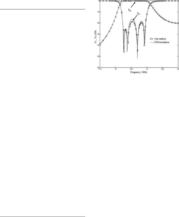
The design of an evanescent mode Chebyshev bandpass filter in the K-band will be carried out with the following specifications:
bandwidth: [18.2–19 GHz ]
ripple in bandwidth: 0.1 dB
insertion loss in the stop band: L ¼ 30 dB at 17.5 GHz and L ¼ 25 dB at 25 GHz.
According to the design theory [5], a 4th order Chebyshev bandpass filter using a cascaded impedance inverter and a unit element (UE) will be sufficient. The normalized impedance of UE sections is given in Table I as well as the reduced inverter impedance.
This filter will be realized with E-plane dielectricloaded metallic waveguide resonators, which are coupled between them by impedance inverters. This latter is made up of sections of empty guide under cut-off. To ensure the coupling by evanescent modes in the frequency band of interest, we retained a standard WR 28 waveguide (a b ¼ 7.112 3.556 mm2) as basic waveguide. The rectangular dielectric inserted in the guide has a thickness of t ¼ 0.3a and a relative permittivity of er ¼ 2.25, which corre-
Discontinuities Analysis by NMVF 81
Figure 7. Variation of K inverter parameters versus the evanescent waveguide section length.
sponds to a cut-off frequency of 12.35 GHz for the loaded basic guide, whereas the sections of the empty basic guide have a cut-off frequency of 21.9 GHz. Thus, the coupling between two loaded resonators is obtained with an evanescent empty waveguide section. The access guides have the same height as the standard WR28 waveguide but their width is equal to 14 mm. Only the TE10 mode is propagating in the frequency range of interest.
Figure 6. Top view of 4th order evanescent mode bandpass filter.
International Journal of RF and Microwave Computer-Aided Engineering DOI 10.1002/mmce
82 Lilonga-Boyenga, Tao, and Vuong
TABLE II. Initial Length of the Filter Resonators and Inverter Sections
Inverter Length |
Resonator Length |
Li (mm) |
LRi (mm) |
|
|
3.35 |
5.53 |
7.1 |
5.39 |
8 |
5.39 |
7.1 |
5.53 |
3.5 |
|
|
|
The NMVF combined with an optimization process enabled us to carry out the design of a 4th order filter as shown in Figure 6.
To determine the length of each evanescent section, the NMVF has been applied to a cascaded discontinuity formed by the combination: loaded wave- guide–evanescent waveguide–loaded waveguide. The variation of K inverter parameters versus the evanescent waveguide section length is given in Figure 7.
From this calculation, the first-order inverter and resonator lengths are obtained, and given in Table II.
These parameters are then introduced into an optimization program in which the error function is defined by
f |
ð |
L0; Li; LRi |
Þ ¼ Xfi |
|
S11g |
2 |
|
S21g |
2 |
S f |
S f |
||||||||
|
|
|
11ð iÞ |
þ Xfj |
|
21ð jÞ |
|
Here Sijg corresponds to the filter specification when Sij(fi) are obtained from the NMVF analysis of the entire filter structure. fi and fj correspond respectively to the sample frequencies in the passband and stopband.
The optimized dimensions are given in Table III and the filter response curve in Figure 8. Very good agreement can be observed with a finite element method simulation.
4. CONCLUSION
Three uniaxial discontinuity structures have been analyzed by a new multimodal varational formulation.
TABLE III. Optimized Lengths of the Filter Resonator and Inverter Sections
|
Inverter |
Resonator |
L0 (mm) |
Length Li (mm) |
Length LRi (mm) |
|
|
|
14.2 |
1 |
4.8 |
|
6 |
5.4 |
|
8.1 |
5.4 |
|
6 |
4.8 |
|
1 |
|
|
|
|
Figure 8. Return losses and insertion losses of 4th order optimized evanescent mode filter
It is shown that this method based on Z (overall structure impedance) calculation leads to higher accuracy and significant reduction in computation time, as compared to the classical MVM, which requires studying the convergence of the parameters according to the number of accessible modes. This new multimodal variational formulation provides a suitable basis of studying and designing various types of complex structures including multiple cascaded uniaxial discontinuities.
REFERENCES
1.R. Sorrentino (eds), Numerical methods for passive microwave and millimeter wave structures, IEEE Press, New York, 1989.
2.H. Patzelt and F. Arndt, Double-plane steps in rectangular waveguides and their application for transformers, irises, and filters, IEEE Trans Microwave Theory Tech MTT-30 (1982), 771–776.
3.J.W. Tao and H. Baudrand, Multimodal variational analysis of uniaxial waveguide discontinuities, IEEE Trans Microwave Theory Tech 39 (1991), 506–516.
4.J.C. Nanan, J.W. Tao, H. Baudrand, B. The´ron, and S. Vigneron, A two-step synthesis of broadband rigged bandpass filters with improved performances, IEEE Trans Microwave Theory Tech 39 (1991), 2192–2197.
5.Ian Hunter, Theory and design of microwave filters, vol. 48 (IEE Electromagnetic waves series), IEE, London, UK, 2001.
6.P. Couffignal, Contribution to metallic waveguide filter analysis, PhD Dissertation (In French), INP Toulouse, 1992.
International Journal of RF and Microwave Computer-Aided Engineering DOI 10.1002/mmce

Discontinuities Analysis by NMVF 83
BIOGRAPHIES
De´sire´ LILONGA-BOYENGA was born in Ekouli, Congo-Brazzaville, in 1956. He received the Maı´trise degree in physics from the University of Pau, in 1980, the DEA degree in physics from the University of Bordeaux I, in 1981, the 3rd cycle doctor degree in electronics from the Institut National Polytechnique of Toulouse (INPT), Toulouse, in 1984, and the Ph.D. degree from INPT
in 2005. From 1985 to 2001, he was with the University Marien NGOUABI of Brazzaville as Maı´tre-assistant. From 2002 to 2005, he was with the electronics laboratory of ENSEEIHT, Toulouse, France, where he is involved on the numerical modeling of waveguide discontinuities and the application to waveguide filter design.
Junwu TAO was born in Hubei, China, in 1962. He received the B.Sc. degree in electronics from the Radio Engineering Department, Huazhong (Central China), University of Science and Technology, Wuhan, China, in 1982, the Ph.D. degree (with honors) from the Institut National Polytechnique of Toulouse (INP), France in 1988, and the Habilita-
tion degree from the University of Savoie, France in 1999. From 1983 to 1991, he was with the electronics laboratory of ENSEEIHT, Toulouse, France, where he worked on the application of various numerical methods to twoand three-dimensional problems in electromagnetism, and the design of microwave and millimeter-wave device. From 1991 to 2001, he was with the microwave laboratory (LAHC) at the University of Savoie, Chambe´ry, France, where he was an associate professor in electrical engineering and involved in the full wave characterization of discontinuity in various planar waveguides and the nonlinear transmission line design. Since September 2001, he is a full position professor at INP Toulouse where he is involved in the numerical methods for electromagnetism, microwave and RF components design, microwave, and millimeter-wave measurements.
Tan Hoa VUONG was born in Saigon, Vietnam. He received the Doctor degree (with honors) from the Institut National Polytechnique of Toulouse (INP), France, in 2000. Since 2000, he is with the laboratory of electronics at ENSEEIHT-INPT and involved in several research collaborations with laboratories and industry of Toulouse, Grenoble, Paris, and Aix in
Provence, as well as with the laboratories in Brazil, Morocco, and Tunisia. Dr. VUONG received the Le´opold ESCANDE prize for the best Ph.D. dissertation of INPT in 2001.
International Journal of RF and Microwave Computer-Aided Engineering DOI 10.1002/mmce