

диафрагмированные волноводные фильтры / a0710d86-bd23-440b-969f-39e2486b88ff
.pdfA Micromachined 805 GHz Rectangular Waveguide
Filter on silicon wafers
Dan Lei1,2, Shuang Liu1, Yong Zhang1, Jiang Hu1, Li Li1, Wei Zhao1 and Ruimin Xu1
1. Fundamental Science on EHF Laboratory, University of Electronic Science and Technology of China, Chengdu, China
2. Department of Physics, Chengdu University of Technology, Chengdu, China E-mail leidan1008@l63.com
Abstract —In this letter, a WR-1.0 rectangular waveguide band-pass filter is designed, which is fabricated using the deep reactive ion etching (DRIE) micromachining on silicon wafers. The filter consists of four inductive irises. Using Ansoft HFSS, the center frequency of the filter is at 805GHz and the insertion loss is about 1.5 dB within the 21GHz bandwidth. Effects of the DRIE process brought to the filter performance are also discussed.
Index Terms —Waveguide band-pass filter, DRIE, WR-1.0
I. INTRODUCTION
There is increasing interest in using Terahertz (THz) frequencies for high data rate communications, military, security scanning and atmospheric monitoring applications. Rectangular waveguide filter is critical at terahertz frequencies as one of the key passive components. Compared with planar transmission line filters, rectangular waveguide filters have more advantages in low loss, high power-handling capabilities and circuit-to-circuit interconnection [1].
Unfortunately, the waveguide filter dimension decreases as the frequency increases. Although standard machining techniques can be used to fabricate these THz filters, accuracy and machining tolerances become an issue. Due to their inherently highly accurate dimensional control and low single cost, the micromachining offers a commendable potential option for fabricating [2].
Xiaobang Shang et al. reported a WR-1.5 band (500–750 GHz) waveguide 3rd order band-pass filter, using three silver- coated-layers SU8 photoresist technique. This filter structure is based on three offset resonators and the filter exhibited a 53.7 GHz 3-dB bandwidth at a central frequency of 671 GHz [3].
Carlos A. Leal-Sevillano et al. reported several band-pass filters in the WR-1.5 band, using silicon DRIE micromachining technique. The filter structures are based on the E-plane (with capacitive irises) and the H-plane (with inductive irises) topologies. The center frequencies of filters are respectively at 550 GHz and 640 GHz with relative
bandwidth of 6% [4].
____________________________________
978-1-4799-4 4- /14/$31.00 ©2014 IEEE
In this letter, a rectangular waveguide band-pass filter is designed at the center frequency of 805GHz and fabricated using the silicon DRIE micromachining technique. It consists of four inductive irises for the 3-poles filtering property.
II. DESIGN AND SIMULATION
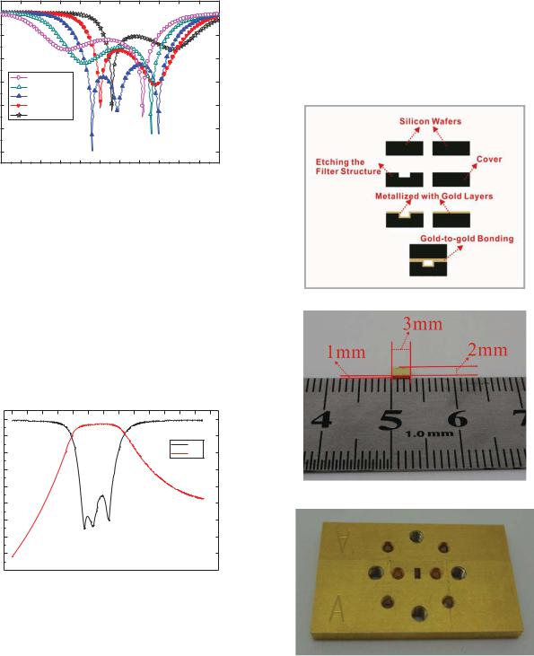
The structure of the band-pass filter is shown in Fig. 1. The initial geometrical structure parameters were calculated with the Chebyscheff filter model [5, 6]. The resonance frequency shifts with the change of the resonator size. The return loss within the pass band can be improved by optimizing the dimensions of inductive irises (t0, t1, t2). As shown in Fig. 2, the location of the irises can affect enormously not only the return loss within the pass band but also the center frequency.
(a)
(b)
Fig. 1 (a) Top view of the proposed filter
(b) 3D schematic of the proposed filter
The band-pass filter is designed with center frequency of 805 GHz. For better integration with other waveguide circuits,
the standard WR-1.0 rectangular waveguides are adopted as
the input and output waveguides. For simple fabrication, the depth of the whole filter structure is all the same (b=127m).
The optimization is accomplished using commercial 3-D electromagnetic software HFSS and the optimized dimensions are listed in Table I
0 |
|
|
|
|
|
|
|
|
|
|
|
-10 |
|
|
|
|
|
|
|
|
|
|
|
-20 |
|
|
|
|
|
|
|
|
|
|
|
-30 |
|
l3=0.048mm |
|
|
|
|
|
|
|
|
|
dB |
|
l3=0.05mm |
|
|
|
|
|
|
|
|
|
|
|
l3=0.052mm |
|
|
|
|
|
|
|
|
|
-40 |
|
l3=0.054mm |
|
|
|
|
|
|
|
|
|
|
|
l3=0.056mm |
|
|
|
|
|
|
|
|
|
-50 |
|
|
|
|
|
|
|
|
|
|
|
-60 |
|
|
|
|
|
|
|
|
|
|
|
775 |
780 |
785 |
790 |
795 |
800 |
805 |
810 |
815 |
820 |
825 |
830 |
|
|
|
|
|
Freq.(GHz) |
|
|
|
|
|
|
Fig. 2 The simulated results of different l3 parameter values
TABLE I
ORIGINAL DIMENSIONS OF THE FILTER
a |
254 m |
b |
127 m |
t1 |
34 m |
l1 |
187 m |
t2 |
137 m |
l2 |
46 m |
t0 |
34 m |
l3 |
52 m |
Because the conductivity of electroplated gold film is less
than that of bulk gold, according to [7], the effective metal conductivity of the gold is set as 3.9 107 S/m in the simulation
model. Taking into account the rough surface of gold, the roughness of the simulation model is set to 0.5m. The
optimized simulated results are shown in Fig. 3, in which the insertion loss is about 1.5 dB within the pass band.
|
0 |
|
|
-5 |
S11 |
|
-10 |
|
|
S21 |
|
|
-15 |
|
dB |
-20 |
|
|
|
|
|
-25 |
|
-30
-35
-40
-45 


 750 760 770 780 790 800 810 820 830 840 850 860 870 880
Freq.(GHz)
Fig. 3 Optimized simulated results of the proposed filter
III. FABRICATION AND DISCUSSION
The proposed waveguide filter is fabricated using DRIE micromachining technique on silicon wafers. The waveguide
filter is constructed using two layer silicon wafers. The bottom wafer is etched using the DRIE process to form the waveguide filtering structure, while the top wafer acts a waveguide cover.
This process can avoid position error of up-to-bottom wafer bonding completely, which is crucial to realize the filter’s
performance while the frequency up to 800GHz. The thickness of the silicon wafer is 500m and depth of etching is 130m. The gold film of 3m thickness is deposited by sputtering on the etched silicon wafer and the cover wafer. And then the two wafers are bonded together, completing the waveguide filter. Several nanometers gold thin film is finally sputtered on the end surfaces for better electrical connection with the measurement setup or other circuits. The main DRIE micromachining process is shown in Fig. 4.
Fig.4 Main DRIE micromachining process
Fig.5 Photograph of the micro-machined filter
Fig.6 Photograph of the text fixture

The photograph of micro-machined filter is shown in Fig. 5, where the size is given by 3 mm 2 mm 1 mm. The test fixture with the flange interface (UG-387) as shown in Fig. 6 is fabricated to fit in the wafer filter so that it can be connected to the measurement system.
[7]H. Jiang, S. Xie and Y. Zhang, Micromachined Terahertz Rectangular Waveguide Band pass Filter on Silicon-Substrate, IEEE Microw. Wirel. Compon. Lett., 22(2012), 636-638
Fig.7 Photograph of the end surface
The waveguide sidewall is not perpendicular to the wafer surface as shown in Fig. 7, which inevitably leading to the resonance cavities volume larger. Consequently, the center frequency may downward, compared with the simulation. Because the text fixture is fabricated using the standard machining techniques, there is imperfect connection between the silicon micro-fabricated filter and the text fixture, which affect absolutely the filter performance.
IV. CONCLUSION
WR-1.0 rectangular waveguide band-pass filter is designed at the center frequency of 805 GHz and is micro-fabricated by using the silicon DRIE micromachining technique. The silicon micro-machined filter has small size and light weight, which is capable of achieving a high degree of integration on a single chip. Effects of the DRIE process brought to the filter performance are also discussed.
REFERENCES
[1]V. M. Lubecke, K. Mizuno, and G. M. Rebeiz, Micromachining for
terahertz applications, IEEE Trans. Microw. Theory Tech., 46(1998), 1821–1831
[2]K. M. K. H. Leong, K. Hennig, C. Zhang, R. Elmadjian, Z. Zhou, B. S. Gorospe, P. P. Chang-Chien, V. Radisic and W. R. Deal, WR1.5 Silicon Micromachined Waveguide Components and Active Circuit Integration Methodology, IEEE Trans. Microw. Theory Tech., 60(2012), 998-1005
[3]Carlos A. Leal-Sevillano, Theodore J. Reck, Cecile Jung-Kubiak, Goutam Chattopadhyay, Jorge A. Ruiz-Cruz, José R. Montejo-Garai, and Jesús M. Rebollar, Silicon Micromachined Canonical E-Plane and H-Plane Bandpass Filters at the Terahertz Band, IEEE Microw. Wirel. Compon. Lett., 23(2013), 288-290
[4]Xiaobang Shang, Yingtao Tian, Michael J. Lancaster and Suren Singh, A SU8 Micromachined WR-1.5 Band Waveguide Filter, IEEE Microw. Wirel. Compon. Lett., 23(2013), 300-302
[5]Jia-Sheng Hong, Microstrip Filters for RF/Microwave Applications, 2rd ed. New York: Wiley, 2011
[6]M. Vahidpour, K.Sarabandi, Micromachined J-band Rectangular Waveguide Filter, General Assembly and Scientific Symposium, 2011 XXXth URSI , 1-4