

диафрагмированные волноводные фильтры / a89050a9-cbb3-4fc0-87c9-4653d067801f
.pdfThis article has been accepted for publication in a future issue of this journal, but has not been fully edited. Content may change prior to final publication. Citation information: DOI 10.1109/TAP.2017.2670438, IEEE Transactions on Antennas and Propagation
Broadband Filtering Dielectric Resonator Antenna with Wide Stopband
P. F. Hu, Y. M. Pan, X. Y. Zhang, S. Y. Zheng
Abstract—A low profile stacked dielectric resonator antenna (DRA) and a microstrip metasurface (MS) antenna are investigated and compared in this paper. It has been found that very similar radiation performance including resonant modes, reflection coefficients, boresight gains and radiation patterns can be obtained between them, indicating that the dielectric superstrate of stacked DRA plays analogous role with MS in enhancing the antenna bandwidth and realized gain. Based on this observation, a broadband, low profile and high gain filtering cylindrical stacked DRA is inspired by a MS-based filtering antenna. Four resonant modes including the higher order HEM31 mode and HEM13 mode are simultaneously excited in the DRA to provide a broad bandwidth of 61.4% and a peak gain of 11.4 dBi within passband, whereas a shorting via and two pairs of transverse stubs are introduced into the feeding microstrip line to generate radiation nulls in stopband and realize filtering function. Second harmonic suppression has been achieved without increasing the footprint of the antenna, and an out-of-band suppression of more than 23dB is obtained within the wide stopband.
Index Terms—Dielectric resonator antenna (DRA), Filtering antenna, Broadband antenna.
I.INTRODUCTION
With the rapid development of high speed wireless communication, there is an increasing demand for broadband operation. On the other hand, the harmonics originated from the non-linearity of power amplifiers need be suppressed within wide frequency range for the transmitting chain. For the receiving chain, wide stopband is also necessary to prevent out-of-band signal injecting into low noise amplifiers. All of these indicate that both broad operating band and wide stopband are of great interest in the RF front-ends. The requirement can be fulfilled by cascading broadband antennas and filters. However, this increases the complexity and volume of the RF front-end. Also, the inevitable insertion loss of filter will degrade the system performance. In recent years, the co-design of antenna and bandpass filter has drawn much attention due to its miniaturized circuit size [1]-[12]. Different from the traditional cascaded design approach in which the filter and antenna are individually designed and cascaded with each other, the co-design scheme treats the filter and antenna as a subsystem. Consequently, matching circuit has been greatly simplified and overall size of the filtering antenna can be considerably reduced. Various
Manuscript received Jun 16, 2016, revised Dec 16, 2016, accepted Jan 1, 2017. This work was supported in part by the National Natural Science Foundation of China under Grant 61302001, in part by the Guangdong Natural Science Funds for Distinguished Young Scholars 2016A030306007, and in part by the Pearl River Nova Program of Guangzhou under Grant 201506010005.
P. F. Hu, Y. M. Pan and X. Y. Zhang are with the School of Electronic and Information Engineering, South China University of Technology, Guangzhou 510641, China. S. Y. Zheng is with the Department of Electronics and Communication Engineering, Sun Yat-sen University, Guangzhou 510006, China. (Corresponding Author: Yongmei Pan, Email: eeympan@scut.edu.cn)
filtering antennas that feature filter-like frequency response for both reflection coefficient and realized gain have been developed, including inset patch antenna [4], slotted cavity antenna [5, 6] and horn antenna [7], but the operating bandwidths of most reported designs are less than 20% and the corresponding stopbands are considerably narrow. It is still a challenge to design high gain and wideband filtering antenna using the co-design approach.
Microstrip metasurface (MS) that consists of electrically small surface scatters has been widely used to design wideband antennas [13, 14]. Recently, a low profile and wideband MS-based filtering antenna was proposed by the authors [11]. The design was developed from an aperture coupled grid-slotted patch MS antenna [14], in which the filtering function was realized by adding a shoring via and two extended stubs into the feeding mircrostrip line. A 10-dB impedance bandwidth of 28.4% and an average gain of 8.2 dBi were obtained within passband due to the MS, and an out-of-band suppression level of more than 20 dB was realized within stopband by virtue of the slightly modified feeding circuit.
Dielectric resonator antenna (DRA) and microstrip antenna are very close in some aspects as they have similar feed mechanisms and radiation patterns [15]. In this paper, it is found that a two-layer stacked DRA exhibits very similar performances including the enhanced impedance bandwidth and boresight gain with the microstrip MS antenna. Due to the three dimensional (3-D) configuration and diverse permittivity of DRA, it can be optimized to provide even more superior performances. Based on this observation, a low profile, broadband and high gain cylindrical filtering DRA (FDRA) is evolved from the previous filtering MS antenna [11]. The FDRA has a low profile of 0.078 0, an impedance bandwidth of 61.4% and an average gain of 8.73 dBi within passband. Also, it shows second harmonic suppression, with out-of-band suppression of more than 23dB obtained within very wide stopband. To the best of our knowledge, it is the broadest passband and stopband that can be obtained thus far from a simple co-designed broadside filtering antenna.
II.BROADBAND STACKED DRAS
Fusion design approach [10-12] is implemented to realize the broadband filtering DRA. Therefore, a broadband stacked DRA is developed first in this section.
A. Comparison of Microstrip MS Antenna and Stacked DRA
It was verified that the dielectric superstrate and metallic patch MS of resonant cavity antenna (RCA) can be appropriately designed to have the same reflection coefficients, and consequently provide the same improving effect on the antenna performance [16]. In the RCA, the superstrate is placed a half wavelength above the feeding source, and it is mainly used to serve as a reflective plate which forms a resonant cavity with the ground plane. In this paper, both of the superstrates are directly placed above a microstrip-coupled slot. Consequently, the height of the overall antenna is reduced and a low profile configuration is realized. On the other hand, the superstrates in this case mainly play the role of resonator but not reflector. Therefore,
0018-926X (c) 2016 IEEE. Personal use is permitted, but republication/redistribution requires IEEE permission. See http://www.ieee.org/publications_standards/publications/rights/index.html for more information.

This article has been accepted for publication in a future issue of this journal, but has not been fully edited. Content may change prior to final publication. Citation information: DOI 10.1109/TAP.2017.2670438, IEEE Transactions on Antennas and Propagation
the resonant modes of the low profile MS antenna and DRA are investigated here instead of the reflection characteristics.
Fig. 1 shows configurations of the low profile microstrip MS antenna [14] and stacked DRA. As shown in Fig. 1(a), the MS consists of 4 ×4 uniform rectangular metallic patches. The patch units with length of l and width of w are evenly distributed along the x and y axes, and the gap width between two adjacent units is given by g. For ease of assembly, the MS is fabricated on a substrate with thickness of h2 = 3 mm and relative permittivity of εr2 = 2.2 which is available in our laboratory. As shown in Fig. 1(b), the stacked DRA consists of two rectangular dielectric planar layers. The top layer (superstrate) has a permittivity of εr3, a length of l1, a width of w1 and a height of h3, and the bottom layer (substrate) is set the same with that of MS for fair comparison. Also, the MS antenna and DRA share the same feeding circuit. Both antennas are fed at the center by a microstrip-coupled slot that fabricated on a substrate with thickness of h1 = 0.813 mm and relative permittivity of εr1 = 3.38.
For ease of comparison, both MS antenna and DRA are designed to operate at ~5 GHz. Fig. 2 shows reflection coefficients and boresight gains of the two antennas and the detailed dimensions are listed in its caption. It is interesting to find that either MS antenna or DRA has two resonant modes excited in the passband, and their resonance frequencies are very close to each other. The lower resonances are at 4.5 and 4.45 GHz, while the upper resonances are at 5.3 and 5.25 GHz, respectively. The surface current distributions on the MS and resonant E-filed patterns inside the DRA are compared in Fig. 3. It can be observed that the current at 4.5 GHz is mainly concentrating on the central units of the MS, and quite similar E-filed distribution is found in the DRA. At 5.25 GHz, the current on the outer patches of MS becomes dominant. Again, the E-field of the DRA has a very similar distribution. Owing to the two similar resonant modes, comparable impedance bandwidths have been obtained by the two antennas. With reference to Fig. 2, the MS antenna has a 10-dB impedance bandwidth of 28% (the same with that of [14]) and the DRA has a bandwidth of 30.3%. The gain curves of the MS-antenna and stacked DRA also show similar changing trend. Both of them can provide relatively high gain, with their average gains given by 10.4 dBi and 9.5 dBi, respectively. The radiation patterns of the two antennas are also compared to further demonstrate their similarity. It is found that almost the same broadside radiation patterns are observed at both resonance frequencies 4.5 and 5.25 GHz, verifying again that the corresponding resonant modes of the two antennas have similar radiation performance.
In view of the above results, it can be concluded that the dielectric superstrate of stacked DRA plays analogous role with the metallic microstrip MS in reshaping the aperture field, and thus widening the antenna bandwidth and enhancing antenna gain. Although wideband and/or high gain stacked DRA has been reported [17]-[19], but it is the first time that the physical insight behind its superior performance is explained from this viewpoint. In the next section, it will be shown that due to the 3D configuration and diverse permittivity of the dielectric superstrate, the stacked DRA has a potential to achieve wider bandwidth which can be used in the design of broadband filtering antenna.
Fig. 1 Configurations of the low profile reference MS antenna and stacked DRA. (a) Reference MS antenna. (b) Stacked DRA.
|S11|(dB) |
|
|
|
Gain(dBi) |
15 |
|
0 |
|
|
|
|
|
|
|
|
|
|
|
|
10 |
-10 |
|
|
|
|
|
|
|
|
|
|
|
|
5 |
-20 |
|
|
|
|
|
0 |
|
|
|
|
|
|
-5 |
-30 |
|
|
|
|
|
|
|
|
|
|
Stacked DRA |
|
-10 |
|
|
|
|
Ref. MS antenna |
|
|
-40 |
|
|
|
|
|
-15 |
3.5 |
4.0 |
4.5 |
5.0 |
5.5 |
6.0 |
|
|
|
Frequency(GHz) |
|
|
|
|
Fig. 2 Reflection coefficients and boresight gains of the low profile reference |
||||||
MS antenna and stacked DRA. h1 = 0.813mm, h2 = 3 mm, h3 = 2.35mm, l = |
||||||
13.2 mm, w = 11.5 mm, g = 1mm, l1 = 51 mm, w1 = 47 mm, εr1 = 3.38, εr2 = |
||||||
2.2, εr3 = 15, ls = 32 mm, ws = 2 mm, lm = 9.5 mm, wm = 1.88 mm, Gl = Gw= |
||||||
70 mm. |
|
|
|
|
|
|
Jsurf[A_per_m] |
E Field[V_per_m |
6.00e+000 |
6.00e+002 |
5.34e+000 |
5.34e+002 |
4.68e+000 |
4.69e+002 |
4.02e+000 |
4.04e+002 |
3.36e+000 |
3.39e+002 |
2.70e+000 |
2.73e+002 |
2.04e+000 |
2.08e+002 |
1.38e+000 |
1.43e+002 |
7.23e-001 |
7.79e+001 |
6.35e-002 |
1.26e+001 |
Ref. MS antenna |
Stacked DRA |
(a) |
|
Jsurf[A_per_m] |
E Field[V_per_m |
6.00e+000 |
6.00e+002 |
5.34e+000 |
5.34e+002 |
4.68e+000 |
4.69e+002 |
4.02e+000 |
4.04e+002 |
3.36e+000 |
3.39e+002 |
2.70e+000 |
2.73e+002 |
2.04e+000 |
2.08e+002 |
1.38e+000 |
1.43e+002 |
7.23e-001 |
7.79e+001 |
6.35e-002 |
1.26e+001 |
Ref. MS antenna |
Stacked DRA |
(b) |
|
Fig. 3 Simulated current distributions |
on the reference MS antenna and |
E-field patterns in the stacked DRA. (a) 4.5GHz. (b) 5.25GHz.
0018-926X (c) 2016 IEEE. Personal use is permitted, but republication/redistribution requires IEEE permission. See http://www.ieee.org/publications_standards/publications/rights/index.html for more information.
This article has been accepted for publication in a future issue of this journal, but has not been fully edited. Content may change prior to final publication. Citation information: DOI 10.1109/TAP.2017.2670438, IEEE Transactions on Antennas and Propagation
B. Optimization of the Stacked DRAs
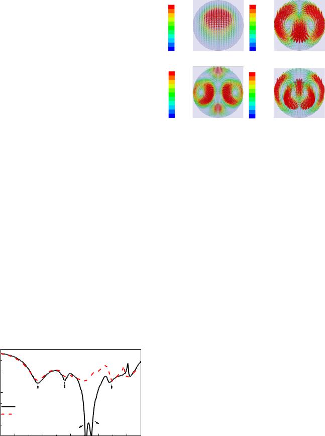
Since the main aim of this paper is to design a broadband filtering antenna, the above rectangular DRA is optimized to further enhance its bandwidth. Cylindrical DRA is more popular in commercial market due to its mature production technology, and therefore a similar stacked cylindrical DRA is also studied in this subsection (Here, it is worth mentioning that a slot coupled cylindrical stacked DRA has been investigated in [19], but its two DR units are made of the same material. However, in the presented stacked DRA, different permittivities are used to design the two layers). Fig. 4 shows reflection coefficients of the two stacked DRAs. With reference to the figure, the reflection coefficients are almost the same at the lower passband, but the matching of cylindrical DRA is much better than that of the rectangular one in the upper band. As a result, a wider impedance bandwidth of 55.18% is achieved by the former. It is noted that five resonant modes are excited within the operating band, contributing to the wide bandwidth. Among them, the mode at 6.5 GHz is caused by the feeding slot since it is found to be very sensitive to the slot length, whereas the other four modes are due to the DRA. To characterize the resonant modes of DRA, their corresponding E-field distributions at 4.8 GHz, 5.8 GHz, 6.8 GHz and 7.4 GHz are shown in Fig. 5. It can be deduced from the patterns that the four modes correspond respectively to the HEM11 , HEM12 , HEM31 (its field is a bit disturbed by the very close slot mode) and HEM13 modes of cylindrical DRA [20]. The higher order HEM12 mode has been investigated recently in designing dualband DRAs [19], [21]-[23], but it is the first time to utilize the HEM31 and HEM13 modes in DRA design although they have been studied theoretically in [20]. It was found that the dual-layer configuration [19] plays an important role in exciting the modes simultaneously. The bottom dielectric layer of the stacked DRA is excited by the feeding slot, whereas the superstrate is mainly excited by the bottom layer. By properly choosing the permittivity and dimensions of the two layers, the four modes merge together and form the wide passband.
The boresight antenna gains of the cylindrical and rectangular DRAs have also been compared. It is found that the gain of rectangular DRA changes significantly from one resonant mode to the next, and it even decreases to 5 dBi near
|S11|(dB) |
|
|
|
|
0 |
|
|
|
|
-10 |
|
|
|
|
-20 |
HEM11 |
HEM12 |
|
HEM13 |
|
|
|||
|
Cylindrical stacked DRA |
|
|
|
-30 |
Rectangular stacked DRA |
|
|
|
|
|
Slot mode |
|
HEM31 |
-40 |
|
|
|
|
4 |
5 |
6 |
7 |
8 |
|
|
Frequency(GHz) |
|
|
Fig. 4 Simulated reflection coefficients of the cylindrical and rectangular stacked DRAs.
E Field[V_per_m |
E Field[V_per_m |
8.00e+002 |
8.00e+002 |
7.15e+002 |
7.15e+002 |
6.32e+002 |
6.32e+002 |
5.47e+002 |
5.47e+002 |
4.63e+002 |
4.63e+002 |
3.79e+002 |
3.79e+002 |
2.95e+002 |
2.95e+002 |
2.11e+002 |
2.11e+002 |
1.27e+002 |
1.27e+002 |
4.31e+001 |
4.31e+001 |
(a) 4.8GHz |
(b) 5.8GHz |
E Field[V_per_m |
E Field[V_per_m |
6.00e+002 |
8.00e+002 |
5.38e+002 |
7.15e+002 |
4.76e+002 |
6.32e+002 |
4.14e+002 |
5.47e+002 |
3.52e+002 |
4.63e+002 |
2.90e+002 |
3.79e+002 |
2.28e+002 |
2.95e+002 |
1.66e+002 |
2.11e+002 |
|
|
1.04e+002 |
1.27e+002 |
4.30e+001 |
4.31e+001 |
(c) 6.8GHz |
(d) 7.4GHz |
Fig. 5 Simulated resonant E-field on the top layer of cylindrical stacked DRA.
6.9 GHz, with its 3-dB gain bandwidth given by 41.07%. However, a more flat gain response can be obtained by the cylindrical DRA, leading to a wider gain bandwidth of 51.48%. The average gain is about 8.5dBi within passband. These results show that the cylindrical stacked DRA has superior impedance and gain bandwidth, and thus is preferable to the design of broadband FDRA.
III. CYLINDRICAL FILTERING DRA
The similarity between the stacked DRA and microstrip MS antenna inspires us that it should be capable to integrate the filtering function into the DRA by using a similar feeding circuit of the MS filtering antenna [11]. A broadband, low profile and high gain filtering DRA will then be obtained.
A. Configuration and Mechanism of the Cylindrical FDRA
Fig. 6 shows configuration of the proposed cylindrical filtering DRA. As can be seen from Fig. 6(a), the stacked DRA consists of two planar dielectric layers, similar to the above configuration. A smaller bottom layer is used to improve the impedance match. Modifications such as separated slots, shorting via and transverse stubs are introduced into the feeding circuit to integrate the filtering function into the DRA, as shown in Fig. 6(b). To investigate how the filtering performance gradually shows up with the variations, Fig. 7 shows boresight gains for the DRAs with different feeding circuits. With reference to the figure, no obvious filtering effect can be observed by using the conventional microstrip-coupled slot (I). It is found in HFSS study that the unwanted mode at 2.4 GHz is caused by the resonance of slot. Therefore, two separated slots (II) are used instead of a continuous one to restrict the excitation of slot mode in lower stopband. Also, an additional shorting via (III) is embedded into the substrate to produce a radiation null right near the lower passband edge, greatly improving the roll-off rate [11]. However, the filtering response of antenna gain in upper stopband is still not satisfying. It can be observed that there is only one radiation null at 11.3 GHz when a simple microstrip feed-line is used. The E-fields on the left and right sides of the DRA at the frequency are found
0018-926X (c) 2016 IEEE. Personal use is permitted, but republication/redistribution requires IEEE permission. See http://www.ieee.org/publications_standards/publications/rights/index.html for more information.

This article has been accepted for publication in a future issue of this journal, but has not been fully edited. Content may change prior to final publication. Citation information: DOI 10.1109/TAP.2017.2670438, IEEE Transactions on Antennas and Propagation
to be out-of-phase, thus the radiation at the boresight direction is cancelled out which produces the radiation null. It is worth mentioning that the mode is very weakly excited and the reflection coefficient is close to 0dB at nearby frequencies, therefore the radiation at other angles is also negligible. As shown by the red dash line, another radiation null is produced at 8.8 GHz when a pair of transverse stubs (IV) is extended from the microstrip line, leading to a high roll-off rate at upper passband edge. This is because current mainly concentrates along the microstrip line when stubs are introduced, and little energy can be coupled to the DRA through slot, causing the radiation null. The length of the open stub is about a quarter wavelength of the microstrip line. The same is true for introducing the second pair of shorter transverse stubs (V). As shown by the black solid line, a third radiation null at 13.4 GHz is generated to further enhance the stopband bandwidth. As a result, the harmonic at 14 GHz is effectively eliminated, and an satisfying out-of-band suppression is realized up to 15 GHz. Compared with the traditional filter cascaded design, this proposed filtering DRA successfully achieve second harmonic suppression without increasing the footprint and height of antenna.
B. Measurement Verification
A prototype of cylindrical FDRA operating at C band was designed, fabricated and measured for demonstration. Fig. 8
(a) Side view
(b) Feeding circuit
Fig. 6 Configuration of the cylindrical filtering DRA. (a) Side-view. (b) Feeding circuit.
I
II |
IV |
|
III |
|
V |
|
||
|
||
|
||
|
|
|
|
|
|
|
|
|
|
|
|
Fig. 7 Simulated boresight gains for the filtering DRAs with different feeding circuits.
shows a photograph of the prototype, with the detailed dimensions given in its caption. The dielectric superstrate is fabricated from low loss material (ECCOSTOCK) with εr3 = 15, and the bottom substrate is fabricated by etching a PCB with εr2 = 2.2. The two dielectric layers and the feeding substrate of Rogers 4003 are then cemented together by a very thin layer of instant glue. In this paper, the reflection coefficient was measured using an Agilent N5230A network analyzer, while antenna gain and radiation patterns were measured using a Satimo Starlab System.
Fig. 9 shows simulated and measured reflection coefficients and boresight gains of the prototype. Due to the excitation of multiple higher order modes, the antenna possesses a wide impedance passband as expected. The measured 10-dB impedance bandwidth is 61.4% (4.22 7.96 GHz), agreeing well with the simulated result of 60.8% (4.27 8 GHz). The antenna also shows a wide stopband in the frequency interval of ~0 4 GHz and 8 15 GHz. Both the simulated and measured reflection coefficients in the stopband are close to 0 dB, indicating the nearly total reflection of signal. Moreover, a sharp edge with good selectivity can be found between the passband and stopband. As a result, the resultant reflection coefficient is in the shape of 
 , showing good filtering response. With reference to the boresight gain in Fig. 9(b), again, reasonable agreement can be observed between the simulation and measurement. The measured gain varies from 7 dBi to 11.4 dBi within the passband, with average value given by about 8.73 dBi. Since there are two radiation nulls generated near the passband edge, the gain drops significantly and quickly to below 30 dB and25 dB at 3.5 GHz and 8.8 GHz, leading to high frequency selectivity. As discussed above, the 3.5 GHz null is caused by the shorting via, and the 8.8 GHz null is formed by the pair of transverse stubs having longer length. The introduction of the second pair of short stubs provides an additional null at 13.4 GHz, realizing a second harmonic suppression. Consequently, an out-of-band suppression of more than 32dB is realized in lower stopband of ~0 3.5 GHz and more than 23dB in upper stopband of 8.8 15 GHz. Quasi-elliptic bandpass response is thus achieved. The results indicate that satisfying filtering performance has been realized without scarifying the radiation performance of the antenna.
Fig. 10 shows normalized radiation patterns of the prototype at 4.4 GHz, 6.06 GHz and 7.8 GHz. It can be observed that the antenna has broadside radiation patterns as expected. In the boresight direction, the co-polarized fields of H-plane (xz plane) and E-plane (yz plane) are both stronger than their cross-polarized counterparts by about 28 dB. Since
Fig. 8 Prototype of the filtering DRA operating at C band. h1 = 0.813 mm, h2
= 3 mm, h3 = 1.8 mm, r1 = 23.5 mm, r2 = 9 mm, εr1 = 3.38, εr2 = 2.2, εr3 = 15, ls = 10 mm, ws = 1.8 mm, ls1 = 4 mm, ws1 = 1 mm, s = 0.4 mm, d = 0.15mm, d0 = 0.65mm, g = -0.1 mm, g1 = 2.6mm, wm = 1.9 mm, lm = 5.6 mm, lp = 4.95
mm, wp = 1.75 mm, lp1 = 3.5 mm, wp1 = 0.3 mm, Gl = Gw = 60 mm.
0018-926X (c) 2016 IEEE. Personal use is permitted, but republication/redistribution requires IEEE permission. See http://www.ieee.org/publications_standards/publications/rights/index.html for more information.

This article has been accepted for publication in a future issue of this journal, but has not been fully edited. Content may change prior to final publication. Citation information: DOI 10.1109/TAP.2017.2670438, IEEE Transactions on Antennas and Propagation
|S11|(dB) |
|
|
|
|
|
|
|
0 |
|
|
|
|
|
|
|
-10 |
|
|
|
|
|
|
|
-20 |
|
|
|
|
|
|
|
-30 |
|
|
|
|
|
Simulated |
|
|
|
|
|
|
|
Measured |
|
-40 0 |
2 |
4 |
6 |
8 |
10 |
12 |
14 |
|
|
|
Frequency(GHz) |
|
|
||
|
|
|
|
(a) |
|
|
|
Gain(dBi) |
|
|
|
|
|
|
|
10 |
|
|
|
|
|
Simulated |
|
|
|
|
|
|
|
||
0 |
|
|
|
|
|
Measured |
|
|
|
|
|
|
|
|
|
-10 |
|
|
|
|
|
|
|
-20 |
|
|
|
|
|
|
|
-30 |
|
|
|
|
|
|
|
-40 0 |
2 |
4 |
6 |
8 |
10 |
12 |
14 |
|
|
|
Frequency(GHz) |
|
|
||
|
|
|
|
(b) |
|
|
|
Fig. 9 Simulated and measured reflection coefficients and boresight gains of the prototype. (a) Reflection coefficients. (b). Boresight gains.
TABLE I COMPARISON WITH PREVIOUS FILTERING ANTENNAS
|
Passband |
Average |
Profile |
Suppression |
Stopband |
|
|
||||||
|
||||||
|
Bandwidth |
gain (dBi) |
( l) |
level (dB) |
bandwidth |
|
[4] |
2% |
3.5 |
0.008 |
19 |
0.1 fc |
|
|
|
|
|
|
|
|
[5] |
3% |
4.5 |
0.144 |
19 |
0.05 fc |
|
|
|
|
|
|
|
|
[6] |
6% |
5.7 |
0.11 |
25 |
0.45 fc |
|
|
|
|
|
|
|
|
[9] |
56.6% |
5.4 |
0.003 |
9 |
0.25 fc |
|
|
|
|
|
|
|
|
[10] |
19.6% |
9.7 |
0.1 |
21 |
0.1 fc |
|
|
|
|
|
|
|
|
[11] |
28.4% |
8.2 |
0.05 |
20 |
0.76 fc |
|
|
|
|
|
|
|
|
[12] |
23% |
9.05 |
0.11 |
25 |
0.4 fc |
|
|
|
|
|
|
|
|
This |
61.4% |
8.7 |
0.078 |
23 |
1.02 fc |
|
work |
||||||
|
|
|
|
|
||
fc: center frequency of the operating band |
|
|
||||
l: wavelength at the lowest frequency of passband |
|
|||||
the resonant modes have different field distributions, the shape of radiation patterns slightly varies with frequency. As can be seen from Fig. 10(c), the sidelobe of E-plane increases at higher frequency band, which is consistent with the fact that strong fields of the higher order mode appear near the edges of the DRA. The sidelobe can be suppressed slightly by using a larger ground plane.
30 |
0 |
30 |
Co-pol |
30 |
0 |
30 |
|
|
|
|
|
||||||
60 |
X-pol |
|
60 |
60 |
|
X-pol |
|
60 |
90 |
-40 -30 -20 -10 |
0 90 |
90 |
|
-40 -30 -20 -10 |
0 90 |
||
120 |
|
|
120 |
120 |
|
|
|
120 |
150 |
180 |
150 |
|
|
150 |
180 |
150 |
|
|
|
|
|
|
|
|
||
|
( ) |
|
|
|
|
( ) |
|
|
(a) 4.4 GHz
30 |
0 |
30 |
Co-pol |
30 |
0 |
30 |
|
|
|
|
|
||||||
60 |
X-pol |
|
60 |
60 |
|
X-pol |
|
60 |
90 |
-40 -30 -20 -10 |
0 90 |
90 |
|
-40 -30 -20 -10 |
0 90 |
||
120 |
|
|
120 |
120 |
|
|
|
120 |
150 |
180 |
150 |
|
|
150 |
180 |
150 |
|
|
|
|
|
|
|
|
||
|
( ) |
|
|
|
|
( ) |
|
|
(b) 6.06 GHz
30 |
0 |
30 |
Co-pol |
30 |
0 |
30 |
|
|
|
|
|
||||||
60 |
X-pol |
|
60 |
60 |
|
X-pol |
|
60 |
90 |
-40 -30 -20 -10 |
0 90 |
90 |
|
-40 -30 -20 -10 |
0 90 |
||
120 |
|
|
120 |
120 |
|
|
|
120 |
150 |
180 |
150 |
|
|
150 |
180 |
150 |
|
|
|
|
|
|
|
|
||
|
( ) |
|
|
|
|
( ) |
|
|
(c) 7.8 GHz
Fig. 10 Simulated and measured normalized radiation patterns of the prototype at (a) 4.4 GHz, (b) 6.06 GHz, (c) 7.8 GHz.
Simulated |
Measured. |
A comprehensive comparison between the proposed filtering DRA and previously reported filtering antennas is tabulated in Table I. It is shown that this low profile design has the widest bandwidth for both the passband and stopband, and also a comparatively high gain within passband and a satisfying suppression level within stopband.
C. Discussion
As for a filtering antenna, an important issue is that its bandwidth must be flexibly tuned to meet the requirements of different communication applications, in analogy to the microwave filter. It has been shown above that the resonant modes in passband of present design are mainly controlled by the DRA, whereas the radiation nulls within stopband are mainly introduced by the feeding circuit. Therefore, it is expected that the operating band and its bandwidth of the proposed filtering DRA can be adjusted by tuning the dimensions of the antenna. Fig. 11 shows simulated reflection coefficients and gains of the filtering DRAs with two extreme bandwidths, and the detailed dimensions of the antennas are listed in the caption for reference. It can be seen that a very wide range of bandwidths (from ~16% to 61%) can be
0018-926X (c) 2016 IEEE. Personal use is permitted, but republication/redistribution requires IEEE permission. See http://www.ieee.org/publications_standards/publications/rights/index.html for more information.

This article has been accepted for publication in a future issue of this journal, but has not been fully edited. Content may change prior to final publication. Citation information: DOI 10.1109/TAP.2017.2670438, IEEE Transactions on Antennas and Propagation
|S11|(dB) |
|
|
|
Gain(dBi) |
|
|
||
0 |
|
|
|
10 |
|
|
|
|
|
|
|
|
0 |
|
|
|
|
-10 |
|
|
|
|
|
|
|
|
|
|
|
|
-10 |
|
|
|
|
-20 |
|
|
|
-20 |
|
|
|
|
|
|
|
|
|
|
|
|
|
-30 |
|
|
|
-30 |
|
|
|
|
|
Wide band |
|
|
|
Wide band |
|||
|
|
Narrow band |
-40 |
|
|
Narrow band |
||
2 |
4 |
6 |
8 |
2 |
4 |
6 |
8 |
|
|
Frequency(GHz) |
|
|
Frequency(GHz) |
||||
|
|
(a) |
|
|
|
|
(b) |
|
Fig. 11 Reflection coefficients and antenna gains for the filtering DRA with different bandwidths. (a) Reflection coefficients. (b) Antenna gains. The wideband design has the same dimensions as shown in the caption of Fig. 8, and the parameters of the narrowband design are listed as follows. h1 = 0.813
mm, h2 = 3 mm, h3 = 1.3 mm, r2 = 6 mm, r1 = 26 mm, εr1 = 3.38, εr2 = 2.2, εr3 = 15, ls = 8 mm, ws = 1.8 mm, ls1 = 2.5 mm, ws1 = 1 mm, s = 0.15 mm, d = 0.15 mm, d0 = 0.9 mm, g = 0.1 mm, g1 = 2.6 mm, wm = 1.9 mm, lm = 6.5 mm,
lp = 6.3 mm, wp = 1.3 mm, lp1 = 5.3 mm, wp1 = 0.3mm, Gl = Gw = 60 mm.
obtained by the proposed filtering DRA, demonstrating the flexibility of present design.
It is worth mentioning although acceptable filtering performance can also be achieved by using conventional DRAs, but the resulted filtering antenna has very limited bandwidth (~10%) and relatively lower gain (~7.5 dBi).
IV. CONCLUSION
In this paper, a stacked DRA and a low profile microstrip MS antenna are compared. It has been shown that the dielectric superstrate of DRA plays analogous role with the microstrip MS in reshaping the aperture fields, and they can be designed to have similar improving effect on antenna bandwidth and realized gain.
In the second part of this paper, slight modifications are introduced to the feeding circuit of cylindrical stacked DRA to integrate the filtering function, a low profile, high gain and broadband filtering antenna is thus obtained. The FDRA has a low profile of 0.078 0, an enhanced 10-dB impedance bandwidth of 61.4% and a high average gain of 8.73dBi. Also, it has desirable filtering performance. An out-of-band suppression level of more than 23 dB is achieved in very wide stopband from ~0 15 GHz. It is worth mentioning that different bandwidths ranging from 16% 61.4% can be obtained by tuning the dimensions, and therefore the antenna can be used in various wireless communication systems.
ACKNOWLEDGMENTS
The valuable comments of the reviewers are gratefully appreciated.
REFERENCES
[1].C. T. Chuang and S. J. Chung, “A compact printed filtering antenna using a ground-intruded coupled line resonator,” IEEE Trans. Antennas
Propag., vol. 59, no. 10, pp. 3630-3637, Oct. 2011.
[2].C. Y. Hsieh, C. H. Wu and T. G. Ma, “A compact dual-band filtering patch antenna using step impedance resonators,” IEEE Antennas Wireless Propag. Lett., vol. 14, pp. 1056-1059, May, 2015.
[3].X. W. Chen, F. X. Zhao, L. Y. Yan and W. M. Zhang, “A compact filtering antenna with flat gain response within the passband,” IEEE Antennas Wireless Propag. Lett., vol. 12, pp. 857-860, Jul, 2013.
[4].C. K. Lin and S. J. Chung “A compact filtering microstrip antenna with quasi-elliptic broadside antenna gain response”, IEEE Antennas Wireless Propag. Lett., vol. 10, pp.381-384, May, 2011.
[5].Y. Yusuf, H. T. Cheng and X. Gong, “A seamless integration of 3-D vertical filters with highly efficient slot antennas,” IEEE Trans. Antennas Propag., vol. 59, no. 11, pp. 4016-4022, Nov. 2011.
[6].Y. Yusuf and X. Gong, “Compact low-loss integration of high-Q 3-D filters with highly efficient antennas,” IEEE Trans. Microw. Theory Tech., vol. 59, no. 4, pp. 857-865, Apr. 2011.
[7].G. Q. Luo, W. Hong, H. J. Tang, et al. “Filtenna consisting of horn antenna and substrate integrated waveguide cavity FSS,” IEEE Trans. Antennas Propag., vol. 55, no. 1, pp. 92-98, Jan. 2007.
[8].Z. H. Jiang and D. H. Werner, “A compact, wideband circularly polarized co-designed filtering antenna and its application for wearable devices with low SAR”, IEEE Trans. Antennas Propag., vol. 63, no. 9, Sep. 2015.
[9].J. N. Wu, Z. Q. Zhao, Z. P. Nie, and Q. H. Liu, “A printed unidirectional antenna with improved upper band-edge selectivity using a parasitic loop,” IEEE Trans. Antennas Propag., vol. 63, no. 4, pp. 1832-1837, Apr. 2015.
[10].X. Y. Zhang, W. Duan, and Y. M. Pan, “High-gain filtering patch antenna without extra circuit,” IEEE Trans. Antennas Propag., vol. 63, no. 12, pp. 5883 –5888, Dec. 2015.
[11].Y. M. Pan, P. F. Hu, X. Y. Zhang, and S. Y. Zheng, “A low profile high gain and wideband filtering antenna with metasurface,” IEEE Trans. Antennas Propag., vol. 64, no. 5, pp. 2010-2016. May. 2016.
[12].P. F. Hu, Y. M. Pan, X. Y. Zhang and S. Y. Zheng, “A compact filtering dielectric resonator antenna with wide bandwidth and high gain,” IEEE Trans. Antennas Propag., vol. 64, no. 8, pp. 3645-3651. Aug. 2016.
[13].W. C. Yang, H. Wang, W. Q. Che and J. J. Wang, “A wideband and high-gain edge-fed patch antenna and array using artificial magnetic conductor structures,” IEEE Antennas Wireless Propag. Lett., vol. 12,
pp.769-772, Jul. 2013.
[14].W. Liu, Z. N. Chen, and X. Qing, “Metamaterial-based low-profile broadband aperture coupled grid-slotted patch antenna,” IEEE Trans. Antennas Propag., vol. 63, no. 7, pp. 3325-3329, Jul. 2015.
[15].D. Guha and C. Kumar, “Microstrip patch versus dielectric resonator antenna bearing all commonly used feeds: An experimental study to choose the right element.” IEEE Antennas Propag. Mag., vol. 58, no. 1,
pp.45-55, Feb. 2016.
[16].X. Chen, and Z. Luo, Z. Zheng, P. Feng and K. Huang, “Effective reflective characteristics of superstrates and their effects on the resonant cavity antenna,” IEEE Trans. Antennas Propag., vol. 63, no. 4, pp. 1572-1580, Apr. 2015.
[17].Y. Liu, H. Liu, M. Wei and S. X. Gong, “A low-profile and high-permittivity dielectric resonator antenna with enhanced bandwidth,”
IEEE Antennas Wireless Propag. Lett., vol. 14, pp. 791-794, Mar. 2015.
[18].Y. M. Pan and S. Y. Zheng, “A low-profile stacked dielectric resonator antenna with high-gain and wide bandwidth,” IEEE Antennas Wireless Propag. Lett., vol. 15, pp. 68-71, Feb. 2016.
[19].P. Gupta, D. Guha and C. Kumar, “Dielectric resonator working as feed as well as antenna: new concept for dual-mode dual-band improved design,” IEEE Trans. Antennas Propag. vol. 64, no. 4, pp. 1497-1502, Apr. 2016.
[20].D. Kajfez and P. Guillon, Dielectric Resonators, Norwood: Artech House Inc., 1986.
[21].D. Guha, A. Banerjee, C. Kumar and Y. M. M. Antar, “Higher order mode excitation for high gain broadside radiation from cylindrical dielectric resonator antennas,” IEEE Trans. Antennas Propag., vol. 60, no.1, pp. 71-77, Jan. 2012.
[22].D. Guha, A. Banerjee, C. Kumar and Y. M. M. Antar, “New technique to excite higher order radiating mode in a cylindrical dielectric resonator antenna,” IEEE Antennas Wireless Propag. Lett., vol. 13, pp.15-18, Jan. 2014.
[23].D. Guha, P. Gupta and C. Kumar, “Dualband cylindrical dielectric
resonator antenna employing HEM11δ and HEM12δ modes excited by new composite aperture,” IEEE Trans. Antennas Propag., vol. 63, no.1, pp.433-438, Jan. 2015.
0018-926X (c) 2016 IEEE. Personal use is permitted, but republication/redistribution requires IEEE permission. See http://www.ieee.org/publications_standards/publications/rights/index.html for more information.