

диафрагмированные волноводные фильтры / b0c43d58-0cd9-4c86-ac31-bfa963344da9
.pdfThis article has been accepted for inclusion in a future issue of this journal. Content is final as presented, with the exception of pagination.
IEEE TRANSACTIONS ON MICROWAVE THEORY AND TECHNIQUES |
1 |
Analysis and Design Guidelines for Wideband CRLH SRR-loaded Coplanar Waveguide
Mohamed A. G. Elsheikh , Graduate Student Member, IEEE, Nancy Y. Ammar,
and Amr M. E. Safwat , Senior Member, IEEE
Abstract— This article presents a novel lumped-element equivalent circuit model for split-ring resonator (SRR)-based composite right/left-handed (CRLH) coplanar waveguide (CPW). The proposed model has closed-form expressions in terms of the parameters of the constituent transmission lines and is valid over a wide frequency range. This article also presents a novel slotline to coupled microstrip (MS) line E-plane T-junction. Based on the circuit model and the proposed junction, systematic design procedures for ultrawideband balanced SRR-based CRLH CPW unit cells that benefit from the geometry of the unit cell and do not rely on adding extra components or parametric iterations are developed. This article also explains the layout constraints and presents alternatives to realize wideband designs. Two CPW unit cells using SRR and edge-coupled (EC) SRRs are designed, fabricated, and characterized. Simulations, which are in good agreement with measurements, show that the operating bandwidth can reach 97% and 78.21% for the two cells, respectively.
Index Terms— Composite right/left hand (CRLH), coplanar waveguide (CPW), metamaterial (MTM), microstrip (MS), periodic structures, slotlines, split ring resonators (SRRs), transitions.
I. INTRODUCTION
SPLIT ring resonators (SRRs) are considered as one of the two pillars of metamaterials (MTMs) [1]–[4]. In the last few years, they have been used extensively in numerous applications that include, but are not limited to, composite right/lefthanded (CRLH) lines [5], [6], bandpass filters [7], [8], high pass filters [9], leaky wave antennas [10], wideband anten-
nas [11], and most recently, fluidic sensors [12].
Two of the most common configurations of SRRs are the coplanar waveguide (CPW) loaded with shunt strips and with either SRRs or edge-coupled (EC)-SRRs, as shown in Fig. 1(a) and (b), respectively. Although these structures are distributed in nature, initial models employed lumped components [13]. Over the years, the development has been to augment those lumped models by additional components to account for different aspects, e.g., the physical structure [14], the distributed magnetic coupling [15], and the inclusion of capacitive coupling [16]. Nevertheless, the resulting designs are typically
Manuscript received January 2, 2020; revised February 18, 2020 and March 27, 2020; accepted March 30, 2020. (Corresponding author: Amr M. E. Safwat.)
The authors are with the Electronics and Electrical Communication Engineering Department, Faculty of Engineering, Ain Shams University, Cairo 11517, Egypt (e-mail: mohamed.a.g.elsheikh@eng.asu.edu.eg; nancyammar@live.com; asafwat@ieee.org).
Color versions of one or more of the figures in this article are available online at http://ieeexplore.ieee.org.
Digital Object Identifier 10.1109/TMTT.2020.2988460
Fig. 1. CRLH CPW loaded with (a) SRR and (b) EC-SRR unit cells. The top conductor is depicted in light gray, while the bottom conductor is in black.
limited in performance as the models are unable to predict the performance over a wideband and cannot relate the values of the electrical components to the physical geometry.
Recently, Elsheikh and Safwat [17], [18] have successfully presented wideband geometry-based models for SRR-loaded CPW and its CRLH counterpart. Moreover, the authors proposed a wideband CRLH SRR-loaded CPW unit cell with the help of extra floating strips. The design relied on parametric sweeps in circuit simulators as a systematic design procedure was not developed. This article aims to investigate the frequency behavior of the CRLH SRR and EC-SRR-loaded CPWs by leveraging the model in [18] to extract a wideband lumped-element equivalent circuit model, which is the counterpart to the conventional ones, link the parameters of the lumped-model to the geometry-based one, and finally develop a systematic procedure and guidelines for balanced designs that best use the geometry of the SRR-based unit cells and do not rely on adding extra components or parametric iterations.
This article is organized as follows: Section II outlines the derivation of the lumped element equivalent circuit models of the SRRand EC-SRR-loaded CRLH CPWs. Section III presents the proposed design guidelines for ultrawideband SRR-loaded CRLH CPW. Section IV depicts the design procedure of a novel slotline-to-coupled microstrip (MS) line E-plane T-junction and describes the design guidelines of balanced EC-SRR CRLH CPW. The experimental verifications of the proposed guidelines for the SRRand EC-SRR-loaded CPWs are described in Sections III and IV, respectively. Finally, the conclusion is drawn in Section V.
II. CRLH SRR-LOADED CPW LUMPED-ELEMENT
EQUIVALENT CIRCUIT MODEL
The extraction of the circuit model elements is a three-step process: exploiting the symmetry conditions, determining the input impedances for the even and odd excitations, and finally, deriving the elements of the -model from these impedances.
0018-9480 © 2020 IEEE. Personal use is permitted, but republication/redistribution requires IEEE permission. See https://www.ieee.org/publications/rights/index.html for more information.
Authorized licensed use limited to: Newcastle University. Downloaded on May 16,2020 at 16:20:43 UTC from IEEE Xplore. Restrictions apply.

This article has been accepted for inclusion in a future issue of this journal. Content is final as presented, with the exception of pagination.
2 |
|
|
|
|
|
|
|
|
|
|
|
|
|
|
|
|
|
|
|
|
|
|
|
|
|
|
|
|
|
|
|
|
|
|
|
|
|
|
|
|
|
|
|
|
|
|
|
|
IEEE TRANSACTIONS ON MICROWAVE THEORY AND TECHNIQUES |
|||||||||||||||||||
|
|
|
|
|
|
|
|
|
|
|
|
|
|
|
|
|
|
|
|
|
|
|
|
|
|
|
|
|
|
|
|
|
|
|
|
|
|
|
|
|
|
|
|
|
|
|
|
|
|
|
|
|
|
|
|
|
|
|
|
|
|
|
|
|
|
|
|
|
|
|
|
|
|
|
|
|
|
|
|
|
|
|
|
|
|
|
|
|
|
|
|
|
|
|
|
|
|
|
|
|
|
|
|
|
|
|
|
|
|
|
|
|
|
|
|
|
|
|
|
|
|
|
|
|
|
|
|
|
|
|
|
|
|
|
|
|
|
|
|
|
|
|
|
|
|
|
|
|
|
|
|
|
|
|
|
|
|
|
|
|
|
|
|
|
|
|
|
|
|
|
|
|
|
|
|
|
|
|
|
|
|
|
|
|
|
|
|
|
|
|
|
|
|
|
|
|
|
|
|
|
|
|
|
|
|
|
|
|
|
|
|
|
|
|
|
|
|
|
|
|
|
|
|
|
|
|
|
|
|
|
|
|
|
|
|
|
|
|
|
|
|
|
|
|
|
|
|
|
|
|
|
|
|
|
|
|
|
|
|
|
|
|
|
|
|
|
|
|
|
|
|
|
|
|
|
|
|
|
|
|
|
|
|
|
|
|
|
|
|
|
|
|
|
|
|
|
|
|
|
|
|
|
|
|
|
|
|
|
|
|
|
|
|
|
|
|
|
|
|
|
|
|
|
|
|
|
|
|
|
|
|
|
|
|
|
|
|
|
|
|
|
|
|
|
|
|
|
|
|
|
|
|
|
|
|
|
|
|
|
|
|
|
|
|
|
|
|
|
|
|
|
|
|
|
|
|
|
|
|
|
|
|
|
|
|
|
|
|
|
|
|
|
|
|
|
|
|
|
|
|
|
|
|
|
|
|
|
|
|
|
|
|
|
|
|
|
|
|
|
|
|
|
|
|
|
|
|
|
|
|
|
|
|
|
|
|
|
|
|
|
|
|
|
|
|
|
|
|
|
|
|
|
|
|
|
|
|
|
|
|
|
|
|
|
|
|
|
|
|
|
|
|
|
|
|
|
|
|
|
|
|
|
|
|
|
|
|
|
|
|
|
|
|
|
|
|
|
|
|
|
|
|
|
|
|
|
|
|
|
|
|
|
|
|
|
|
|
|
|
|
|
|
|
|
|
|
|
|
|
|
|
|
|
|
|
|
|
|
|
|
|
|
|
|
|
|
|
|
|
|
|
|
|
|
|
|
|
|
|
|
|
|
|
|
|
|
|
|
|
|
|
|
|
|
|
|
|
|
|
|
|
|
|
|
|
|
|
|
|
|
|
|
|
|
|
|
|
|
|
|
|
|
|
|
|
|
|
|
|
|
|
|
|
|
|
|
|
|
|
|
|
|
|
|
|
|
|
|
|
|
|
|
|
|
|
|
|
|
|
|
|
|
|
|
|
|
|
|
|
|
|
|
|
|
|
|
|
|
|
|
|
|
|
|
|
|
|
|
|
|
|
|
|
|
|
|
|
|
|
|
|
|
|
|
|
|
|
|
|
|
|
|
|
|
|
|
|
|
|
|
|
|
|
|
|
|
|
|
|
|
|
|
|
|
|
|
|
|
|
|
|
|
|
|
|
|
|
|
|
|
|
|
|
|
|
|
|
|
|
|
|
|
|
|
|
|
|
|
|
|
|
|
|
|
|
|
|
|
|
|
|
|
|
|
|
|
|
|
|
|
|
|
|
|
|
|
|
|
|
|
|
|
|
|
|
|
|
|
|
|
|
|
|
|
|
|
|
|
|
|
|
|
|
|
|
|
|
|
|
|
|
|
|
|
|
|
|
|
|
|
|
|
|
|
|
|
|
|
|
|
|
|
|
|
|
|
|
|
|
|
|
|
|
|
|
|
|
|
|
|
|
|
|
|
|
|
|
|
|
|
|
|
|
|
|
|
|
|
|
|
|
|
|
|
|
|
|
|
|
|
|
|
|
|
|
|
|
|
|
|
|
|
|
|
|
|
|
|
|
|
|
|
|
|
|
|
|
|
|
|
|
|
|
|
|
|
|
|
|
|
|
|
|
|
|
|
|
|
|
|
|
|
|
|
|
|
|
|
|
|
|
|
|
|
|
|
|
|
|
|
|
|
|
|
|
|
|
|
|
|
|
|
|
|
|
|
|
|
|
|
|
|
|
|
|
|
|
|
|
|
|
|
|
|
|
|
|
|
|
|
|
|
|
|
|
|
|
|
|
|
|
|
|
|
|
|
|
|
|
|
|
|
|
|
|
|
|
|
|
|
|
|
|
|
|
|
|
|
|
|
|
|
|
|
|
|
|
|
|
|
|
|
|
|
|
|
|
|
|
|
|
|
|
|
|
|
|
|
|
|
|
|
|
|
|
|
|
|
|
|
|
|
|
|
|
|
|
|
|
|
|
|
|
|
|
|
|
|
|
|
|
|
|
|
|
|
|
|
|
|
|
|
|
|
|
|
|
|
|
|
|
|
|
|
|
|
|
|
|
|
|
|
|
|
|
|
|
|
|
|
|
|
|
|
|
|
|
|
|
|
|
|
|
|
|
|
|
|
|
|
|
|
|
|
|
|
|
|
|
|
|
|
|
|
|
|
|
|
|
|
|
|
|
|
|
|
|
|
|
|
|
|
|
|
|
|
|
|
|
|
|
|
|
|
|
|
|
|
|
|
|
|
|
|
|
|
|
|
|
|
|
|
|
|
|
|
|
|
|
|
|
|
|
|
|
|
|
|
|
|
|
|
|
|
|
|
|
|
|
|
|
|
|
|
|
|
|
|
|
|
|
|
|
|
|
|
|
|
|
|
|
|
|
|
|
|
|
|
|
|
|
|
|
|
|
|
|
|
|
|
|
|
|
|
|
|
|
|
|
|
|
|
|
|
|
|
|
|
|
|
|
|
|
|
|
|
|
|
|
|
|
|
|
|
|
|
|
|
|
|
|
|
|
|
|
|
|
|
|
|
|
|
|
|
|
|
|
|
|
|
|
|
|
|
|
|
|
|
|
|
|
|
|
|
|
|
|
|
|
|
|
|
|
|
|
|
|
|
|
|
|
|
|
|
|
|
|
|
|
|
|
|
|
|
|
|
|
|
|
|
|
|
|
|
|
|
|
|
|
|
|
|
|
|
|
|
|
|
|
|
|
|
|
|
|
|
|
|
|
|
|
|
|
|
|
|
|
|
|
|
|
|
|
|
|
|
|
|
|
|
|
|
|
|
|
|
|
|
|
|
|
|
|
|
|
|
|
|
|
|
|
|
|
|
|
|
|
|
|
|
|
|
|
|
|
|
|
|
|
|
|
|
|
|
|
|
|
|
|
|
|
|
|
|
|
|
|
|
|
|
|
|
|
|
|
|
|
|
|
|
|
|
|
|
|
|
|
|
|
|
|
|
|
|
|
|
|
|
|
|
|
|
|
|
|
|
|
|
|
|
|
|
|
|
|
|
|
|
|
|
|
|
|
|
|
|
|
|
|
|
|
|
|
|
|
|
|
|
|
|
|
|
|
|
|
|
|
|
|
|
|
|
|
|
|
|
|
|
|
|
|
|
|
|
|
|
|
|
|
|
|
|
|
|
|
|
|
|
|
|
|
|
|
|
|
|
|
|
|
|
|
|
|
|
|
|
|
|
|
|
|
|
|
|
|
|
|
|
|
|
|
|
|
|
|
|
|
|
|
|
|
|
|
|
|
|
|
|
|
|
|
|
|
|
|
|
|
|
|
|
|
|
|
|
|
|
|
|
|
|
|
|
|
|
|
|
|
|
|
|
|
|
|
|
|
|
|
|
|
|
|
|
|
|
|
|
|
|
|
|
|
|
|
|
|
|
|
|
|
|
|
|
|
|
|
|
|
|
|
|
|
|
|
|
|
|
|
|
|
|
|
|
|
|
|
|
|
|
|
|
|
|
|
|
|
|
|
|
|
|
|
|
|
|
|
|
|
|
|
|
|
|
|
|
|
|
|
|
|
|
|
|
|
|
|
|
|
|
|
|
|
|
|
|
|
|
|
|
|
|
|
|
|
|
|
|
|
|
|
|
|
|
|
|
|
|
|
|
|
|
|
|
|
|
|
|
|
|
|
|
|
|
|
|
|
|
|
|
|
|
|
|
|
|
|
|
|
|
|
|
|
|
|
|
|
|
|
|
|
|
|
|
|
|
|
|
|
|
|
|
|
|
|
|
|
|
|
|
|
|
|
|
|
|
|
|
|
|
|
|
|
|
|
|
|
|
|
|
|
|
|
|
|
|
|
|
|
|
|
|
|
|
|
|
|
|
|
|
|
|
|
|
|
|
|
|
|
|
|
|
|
|
|
|
|
|
|
|
|
|
|
|
|
|
|
|
|
|
|
|
|
|
|
|
|
|
|
|
|
|
|
|
|
|
|
|
|
|
|
|
|
|
|
|
|
|
|
|
|
|
|
|
|
|
|
|
|
|
|
|
|
|
|
|
|
|
|
|
|
|
|
|
|
|
|
|
|
|
|
|
|
|
|
|
|
|
|
|
|
|
|
|
|
|
|
|
|
|
|
|
|
|
|
|
|
|
|
|
|
|
|
|
|
|
|
|
|
|
|
|
|
|
|
|
|
|
|
|
|
|
|
|
|
|
|
|
|
|
|
|
|
|
|
|
|
|
|
|
|
|
|
|
|
|
|
|
|
|
|
|
|
|
|
|
|
|
|
|
|
|
|
|
|
|
|
|
|
|
|
|
|
|
|
|
|
|
|
|
|
|
|
|
|
|
|
|
|
|
|
|
|
|
|
|
|
|
|
|
|
|
|
|
|
|
|
|
|
|
|
|
|
|
|
|
|
|
|
|
|
|
|
|
|
|
|
|
|
|
|
|
|
|
|
|
|
|
|
|
|
|
|
|
|
|
|
|
|
|
|
|
|
|
|
|
|
|
|
|
|
|
|
|
|
|
|
|
|
|
|
|
|
|
|
|
|
|
|
|
|
|
|
|
|
|
|
|
|
|
|
|
|
|
|
|
|
|
|
|
|
|
|
|
|
|
|
|
|
|
|
|
|
|
|
|
|
|
|
|
|
|
|
|
|
|
|
|
|
|
|
|
|
|
|
|
|
|
|
|
|
|
|
|
|
|
|
|
|
|
|
|
|
|
|
|
|
|
|
|
|
|
|
|
|
|
|
|
|
|
|
|
|
|
|
|
|
|
|
|
|
|
|
|
|
|
|
|
|
|
|
|
|
|
|
|
|
|
|
|
|
|
|
|
|
|
|
|
|
|
|
|
|
|
|
|
|
|
|
|
|
|
|
|
|
|
|
|
|
|
|
|
|
|
|
|
|
|
|
|
|
|
|
|
|
|
|
|
|
|
|
|
|
|
|
|
|
|
|
|
|
|
|
|
|
|
|
|
|
|
|
|
|
|
|
|
Fig. 2. CRLH SRR-loaded CPW unit cell. (a) Physical layout. (b) Geometrybased model. (c) Even excitation circuit. (d) Odd excitation circuit.
Fig. 2(a) shows the conventional design of the CRLH SRR-loaded CPW unit cell. It consists of two SRRs with two shunt metal strips. A perfect H -symmetry boundary bisects the structure as the SRRs are symmetrical with respect to the CPW center conductor (vertical plane) and the even mode excites the CPW. Fig. 2(b) depicts the corresponding geometry-based equivalent circuit model as deduced in [18].
Fig. 2(a) also shows that half the structure is symmetrical with respect to its horizontal plane. Applying the even–odd analysis results in the geometrical circuit models of the even and odd excitations shown in Fig. 2(c) and (d), respectively. Assuming the input transmission lines are matched to the ports, (1) and (2) show that the even and odd input impedances (Zine , Zino ) are the parallel combination of the MS stubs and the input impedance of the host line
Zine |
= − j[Zm1 cot(θ1) + Zm2 cot(θ2)]//Zhost,e |
(1) |
|
Zino |
= j[Zm1 tan(θ1) − Zm2 cot(θ2)]//Zhost,o |
(2) |
|
|
|
j Zs 2ωLstrip + Zs tan(θs) |
|
Zhost,e |
= |
Zs − 2ωLstrip tan(θs) |
(3) |
Fig. 3. CRLH EC-SRR-loaded CPW. (a) Half structure layout with vertical symmetry plane. (b) Quarter structure with vertical and horizontal symmetry planes. (c) Quarter structure with straightened coupled lines. (d) Equivalent circuit model of the coupled line-loaded slotline. (e) Equivalent circuit model of the unit cell.
Zhost,o = j Zs tan(θs) |
(4) |
where Zs is the slotline impedance that results from the vertical bisection and is equal to double the CPW characteristic impedance (Zs = 2Zcpw), Zm1 and Zm2 are the characteristic impedances of the SRR MS lines as shown in Fig. 2(a), assuming that the ring width does not have to be uniform, θ1, θ2, and θs are the electrical lengths of the MS sections and the host slotline, respectively, Zhost,e/o are the input impedances of the slotline terminated by the strip in the even excitation and by a short circuit in the odd excitation as shown in (3) and (4), respectively, and 2Lstrip is the approximate inductance value of the strip terminating the slotline.
The same procedure applies for the CRLH EC-SRR-loaded CPW shown in Fig. 1(b). Fig. 3(a) shows half the structure that results from the vertical perfect H -symmetry plane. Fig. 3(b) depicts the quarter structure after the horizontal cut. The nodes, which lie on the horizontal symmetry plane, are terminated by open and short circuits for the even and odd excitations, respectively. To determine the loading to the slotline, the coupled lines are assumed to be approximately equal in length and they are straightened as shown in Fig. 3(c). Then, they are analyzed as two MS-coupled line sections, each one is backed by one conductor of the slotline, with the strips connected at the junction. The impedances of the coupledline T-network are derived from the four-port Z-parameters of
Authorized licensed use limited to: Newcastle University. Downloaded on May 16,2020 at 16:20:43 UTC from IEEE Xplore. Restrictions apply.

This article has been accepted for inclusion in a future issue of this journal. Content is final as presented, with the exception of pagination.
ELSHEIKH et al.: ANALYSIS AND DESIGN GUIDELINES FOR WIDEBAND CRLH SRR-LOADED CPW |
3 |
the coupled lines [19] by considering two internal ports at the junction, as shown in Fig. 3(c), and applying the boundary conditions corresponding to each excitation. Fig. 3(d) depicts the equivalent T-network for each section of the coupled lines. They are mirror equivalents due to the symmetry and the nodal connections. Fig. 3(e) depicts the even and odd input impedances of the CRLH EC-SRR-loaded CPW which is like the SRR case. The input impedances consist of the input impedances of the host slotline connected in parallel to Zeq,e/o given by the following equations:
Z |
eq,e/o |
= |
Z |
1,e/o + Z3,e/o |
|
+ |
2Z |
2,e/o |
|
|
|
|
|
(5) |
|||||||||
|
2 |
|
|
|
|
|
|||||||||||||||||
|
|
|
|
|
|
|
|
|
|
|
|||||||||||||
|
Z1,e |
= Z3,e = − j Z0o cot(θcl) |
|
|
|
|
|
(6) |
|||||||||||||||
|
|
|
|
|
|
j |
|
|
|
|
|
|
|
|
|
|
|
|
|
|
|
||
|
Z2,e |
= − |
|
|
(Z0e − Z0o) cot(θ cl) |
|
|
|
|
|
(7) |
||||||||||||
|
|
2 |
|
|
|
|
|
||||||||||||||||
|
Zeq,e = − j Z0e cot(θcl) |
|
|
|
|
|
|
|
|
|
|
|
|
(8) |
|||||||||
|
Z |
|
|
−2 j Z0o(Z0e − Z0o) |
|
j Z |
|
cot(θ |
|
) |
(9) |
||||||||||||
|
1,o |
= sin(2θcl)(Z0e + Z0o) − |
0o |
cl |
|||||||||||||||||||
|
|
|
|
|
(10) |
||||||||||||||||||
|
Z2,o |
= |
2 |
(Z0e − Z0o) sin(2θcl) − cot(θcl) |
|||||||||||||||||||
|
|
|
|
j |
|
|
|
|
|
|
|
|
|
|
2 |
|
|
|
|
|
|
|
|
|
Z3,o |
= j Z0o sin(2θcl) − cot(θcl) |
|
|
|
(11) |
|||||||||||||||||
|
|
|
|
|
|
|
|
|
2 |
|
|
|
|
|
|
|
|
|
|
|
|
|
|
Zeq,o |
= |
|
|
|
|
(Z0o + Z0e) sin(2θcl) |
|
|
(12) |
||||||||||||||
|
|
|
|
2 j Z0e |
Z0e sin2(θcl) |
− Z0o cos2(θcl) |
|
|
|||||||||||||||
where Z0e and Z0o are the even and odd characteristic impedances of the MS-coupled lines, respectively, and θcl is the electrical length of the coupled line section (quarter ring), assuming that the even and odd modes have the same phase propagation constants. The subscripts “e” and “o” correspond to the even and odd excitation, respectively.
The final step in the modeling is to map the derived even and odd input impedances to the elements of the -network, shown in Fig. 4(a), by applying the following equations:
Z1 |
= |
Zine |
(13) |
|||
Z |
|
|
Zine − Zino |
. |
(14) |
|
2 |
= |
|
|
|||
|
|
2Zine Zino |
|
|||
The proposed lumped-element equivalent circuit model for the SRR and EC-SRR is shown in Fig. 4(b), while the corresponding equations are depicted in Table I. The symbols of the lumped elements are chosen as depicted because they correspond to the behavior of the design equations at low frequencies (below quarter wavelength). Fig. 4(b) and Table I also show that the series resonator for the SRR can be decomposed into an inductor and a capacitor at low frequency, which is not possible for the EC-SRR. These proposed models provide the equivalent lumped parameters of the unit cells in terms of the transmission line parameters. This enables the comparison with the prevalent lumped models in the literature.
This lumped element model has three main advantages. The first one is that all its components have design equations. From the even analysis, C1 and C2 correspond to the two series open-circuited MS stubs of lengths θ1 and θ2, respectively. Meanwhile, L0 corresponds to the shunt strip-terminated slotline of length θs. From the odd analysis, L1 originates from the shunt short-circuited slotline of length θs. It is to be noted that the inductance L0 can be approximated to L1 if the shunt
Fig. 4. (a) Equivalent two-port network -model. (b) Circuit model of the CRLH SRR and EC-SRR-loaded CPW. (c) and (d) Circuit versus EM for both structures with air substrate. Dimensions as shown in Figs. 2(a) and 3(a)
are as follows: Wcpw = 7 mm, Wcpwe = 5 mm, g = 0.3 mm, Wms = 0.25 mm, l1 = 4.6 mm, l2 = 4.35 (4.6 in circuit simulations) mm, len = 3 mm, lin = 2 mm, r1 = 2.9 mm, r2 = 2.525 mm, Lcl = 4.46 mm, Wstrip = 0.625 mm for the SRR and 0.5 mm for the EC-SRR. Impedances are: Zs = 166 ,
Zm1 = Zm2 = 125 for the SRR, Z0e = 165 and Z0o = 75 for the EC-SRR.
metal strip is considered as an ideal short circuit rather than an inductor. The inductor (L2) and the capacitor (C2) of the series resonator are derived from the short-circuited MS stub of length θ1 and the open-circuited MS stub of length θ2, respectively. It is to be noted that C1 and L2 are tightly linked as their values originate from the same stub with the openand short-circuit terminations, respectively.
The second advantage is that the model provides closedform expressions for the balanced condition. According to Table I and Fig. 4(a) and (b), the balance condition, which is realized when the series branch is short-circuited and the
Authorized licensed use limited to: Newcastle University. Downloaded on May 16,2020 at 16:20:43 UTC from IEEE Xplore. Restrictions apply.

This article has been accepted for inclusion in a future issue of this journal. Content is final as presented, with the exception of pagination.
4
TABLE I
EXPRESSIONS OF THE LUMPED ELEMENTS IN THE CRLH
SRR-BASED CPW UNIT CELLS
shunt branch is open-circuited, can be expressed for the SRR as follows:
Zm2 = Zm1 tan(θ1) tan(θ2) |
(15) |
||
Zs tan(θs) = |
2Zm1 |
(16) |
|
|
. |
||
sin(2θ1) |
|||
While for the EC-SRR, this condition is expressed as follows:
tan2(θcl) = |
Z0o |
|
(17) |
Z0e |
|||
Z0e cot(θcl) = |
Zs tan(θs). |
(18) |
|
Comparing these two sets of equations reveals that for rings of uniform widths, the EC-SRR provides a lower balance frequency than the SRR since in such a case Zm1 = Zm2 and the ring is half-wavelength regardless of the MS impedance, while for the EC-SRR Z0e is larger than Z0o, which translates to a shorter electrical length. For the uncoupled rings, the balance frequencies are the same.
The third advantage is that the proposed model can explain the electrical behavior of the SRR and EC-SRR-loaded CPWs over a wide frequency range, i.e., in-band and out-of-band. This advantage is clarified in Fig. 4(c), which shows the circuit and electromagnetic (EM) simulations of an SRR-loaded CPW. The investigation of this behavior shows that at low frequency, the lumped model reduces to an inductive series branch (as L1 is slightly larger than L0), with an inductive shunt branch dominated by the short-circuited slotline inductance L0. Hence, the CPW does not support propagation. As the frequency increases, the shunt resonator in the series branch resonates forming an open circuit and creates a transmission zero at 4.2 GHz. If the metal strip is approximated to be an ideal short-circuit rather than an inductance, then the input impedances of the slotlines in the even and odd circuits are identical and their inductances in the series branch of the -model are equal (i.e., L1 = L0), and will cancel out eliminating this transmission zero. Beyond that, the overall effect of the series branch becomes capacitive. As noted before, since C1 and C2 are very close in value, the net
IEEE TRANSACTIONS ON MICROWAVE THEORY AND TECHNIQUES
capacitor resulting from the positive and negative capacitors is very small. However, this effective capacitance increases near the resonance frequency of the series LC resonator (2L2 and C2/2, or 2Zseries in general). This, along with the shunt branch being effectively inductive, marks the onset of the left-handed propagation. At 6.96 GHz, the circuit exhibits a reflection zero and full transmission. Partial transmission ensues until the resonance frequency of Zseries, after which, the series branch turns inductive and maximum mismatch occurs, corresponding to the bandgap. The line does not support propagation until the resonance frequency of the shunt branch. As the shunt branch turns capacitive, the unit-cell supports right-handed propagation and a reflection zero occurs at 11.78 GHz. At 16.3 GHz, the ring acts as an open-circuited one-wavelength resonator. Thus, the MS stub shown in Fig. 2(c) becomes half-wavelength resonator and the corresponding capacitance to it, Ceq turns into a short circuit. After this, the shunt branch turns inductive while the series branch turns capacitive, noting that the series resonator in the series branch resonates for the second time turning capacitive again, which is the onset of left-handed propagation. The second left-hand band is wider than the first one as it extends from 16.3 to 24.6 GHz, followed by a narrow stopband gap from 24.6 to 27.3 GHz and the second right-hand band from 27.3 GHz onward.
Fig. 4(d) shows the performance, circuit versus EM, of an EC-SRR-loaded CPW. Discrepancies between simulations, as explained in [18], are due to the discontinuities not accounted for in the circuit model. Same behavior as the SRR-loaded CPW is achieved; however, it is shifted to lower frequency, which is expected as explained earlier.
III. BALANCED CRLH SRR-LOADED CPW DESIGN
GUIDELINES
Full transmission (zero reflection) occurs in SRR or EC-SRR-loaded CPWs when the series and shunt branches of the model shown in Fig. 4(a) satisfy the following equation:
| |
|
1 |
| = |Z2 |
| |
+ |
|
|
|Z2|2 − |
0 |
|
||
|
Z |
|
|
−Z |
02 |
|
|
|
Z04 |
|
Z2 |
(19) |
|
|
|
|
|
|
|
|
|
|
|||
where Z0 is the slotline port impedance.
A similar problem was investigated by Wang et al. [20], to realize an ultra-wideband bandpass filter with a hybrid MS/CPW structure. Inspired by that work, the CRLH SRR-loaded CPW is described hereafter as two slotline-to- MS transitions, connected back-to-back. The slotline-to-MS transition, shown in Fig. 5(a), consists of the open-circuited MS stub (Zm2, θ2), the short-circuited slotline (Zs, θs), and the MS line (Zm1,θ1). The back-to-back transition is shown in Fig. 5(b), which also depicts an internal port inserted at the horizontal symmetry plane of the SRR-loaded CPW. The decoupling between the two transitions is realized by neglecting the inductance of the shunt strip and considering it as an ideal short circuit. This assumption also reduces the circuit model of the CRLH SRR-loaded CPW to the one shown in Fig. 5(c).
Based on this new interpretation, and inspired by Wang et al. [20], the proposed design guidelines are as follows.
Authorized licensed use limited to: Newcastle University. Downloaded on May 16,2020 at 16:20:43 UTC from IEEE Xplore. Restrictions apply.

This article has been accepted for inclusion in a future issue of this journal. Content is final as presented, with the exception of pagination.
ELSHEIKH et al.: ANALYSIS AND DESIGN GUIDELINES FOR WIDEBAND CRLH SRR-LOADED CPW |
5 |
||||||||||||||||||||||||||
|
|
|
|
|
|
|
|
|
|
|
|
|
|
|
|
|
|
|
|
|
|
|
|
|
|
|
|
|
|
|
|
|
|
|
|
|
|
|
|
|
|
|
|
|
|
|
|
|
|
|
|
|
|
|
|
|
|
|
|
|
|
|
|
|
|
|
|
|
|
|
|
|
|
|
|
|
|
|
|
|
|
|
|
|
|
|
|
|
|
|
|
|
|
|
|
|
|
|
|
|
|
|
|
|
|
|
|
|
|
|
|
|
|
|
|
|
|
|
|
|
|
|
|
|
|
|
|
|
|
|
|
|
|
|
|
|
|
|
|
|
|
|
|
|
|
|
|
|
|
|
|
|
|
|
|
|
|
|
|
|
|
|
|
|
|
|
|
|
|
|
|
|
|
|
|
|
|
|
|
|
|
|
|
|
|
|
|
|
|
|
|
|
|
|
|
|
|
|
|
|
|
|
|
|
|
|
|
|
|
|
|
|
|
|
|
|
|
|
|
|
|
|
|
|
|
|
|
|
|
|
|
|
|
|
|
|
|
|
|
|
|
|
|
|
|
|
|
|
|
|
|
|
|
|
|
|
|
|
|
|
|
|
|
|
|
|
|
|
|
|
|
|
|
|
|
|
|
|
|
|
|
|
|
|
|
|
|
|
|
|
|
|
|
|
|
|
|
|
|
|
|
|
|
|
|
|
|
|
|
|
|
|
|
|
|
|
|
|
|
|
|
|
|
|
|
|
|
|
|
|
|
|
|
|
|
|
|
|
|
|
|
|
|
|
|
|
|
|
|
|
|
|
|
|
|
|
|
|
|
|
|
|
|
|
|
|
|
|
|
|
|
|
|
|
|
|
|
|
|
|
|
|
|
|
|
|
|
|
|
|
|
|
|
|
|
|
|
|
|
|
|
|
|
|
|
|
|
|
|
|
|
|
|
|
|
|
|
|
|
|
|
|
|
|
|
|
|
|
|
|
|
|
|
|
|
|
|
|
|
|
|
|
|
|
|
|
|
|
|
|
|
|
|
|
|
|
|
|
|
|
|
|
|
|
|
|
|
|
|
|
|
|
|
|
|
|
|
|
|
|
|
|
|
|
|
|
|
|
|
|
|
|
|
|
|
|
|
|
|
|
|
|
|
Fig. 5. (a) Slotline-to-MS transition. (b) Back-to-back transition. (c) Circuit model of the back-to-back transition.
1)The first reflection zero is set at the center of the operating band ( f0). It corresponds to the fundamental operating frequency of the conventional slotline-to-MS transition [21]. The slotline and MS stubs are a quarter wavelength. The output MS line is also a quarter wavelength and the total length of the MS line in the back-to-back transitions is the half wavelength, i.e., the ring is one wavelength.
2)The second reflection zero ( f1) is placed at the desired CRLH balance frequency. Since the electrical lengths of the stubs and the MS line are equal, (15) and (16) reduce to (20) and (21), respectively, assuming linear dispersion
tan2(θ ) = |
Zm2 |
|
|
(20) |
Zm1 |
|
|
||
Zs = |
Zm1 |
(Zm2 |
+ Zm1) |
(21) |
Zm2 |
where θ = θs = θ1 = θ2.
This zero sets the ratio between the MS impedances of the two sections of the ring (stub and TL) and links the MS impedances to that of the short-circuited slotline. It is to be noted that the wider the bandwidth, the smaller the ratio between Zm2 and Zm1 is.
3)In order to obtain an ultrawideband operation, a third reflection zero is inserted at an intermediate frequency ( f2) of the slotline-to-MS transition (19). This reflection zero fully determines the impedances of the MS ring and the short-circuited slotline in terms of the port impedance.
Implementing these guidelines results in the ultrawideband CRLH SRR-loaded CPW, whose performance is shown in Fig. 6(a) for 100slotline port impedance. The center frequency is f0. The second reflection zero (balance frequency, f1) is at 0.4 f0 and the third one (intermediate one, f2) is set at 0.8 f0. Because of using distributed components, the images of f1 and f2 about f0 appear at f1 (1.6 f0) and f2 (1.2 f0), respectively, and matching is achieved over 140% fractional bandwidth.
Fig. 6. (a) Circuit simulations of the single and back-to-back transitions.
(b) Dispersion relation and Bloch impedance of the back-to-back transition. Zm1 = 93.32 , Zm2 = 49.26 , and Zs = 270 .
To confirm the periodic behavior of the unit cell, the Bloch impedance and the dispersion relation are inferred from the S-parameters according to [4]. Both are depicted in Fig. 6(b). The left-hand band is from 0.22 f0 to 0.4 f0. Because the unit cell is balanced, the right-hand band starts at 0.4 f0 and ends at f0, where the phase is 180◦. At this frequency, 2θ1 corresponds to half wavelength. The phase then decreases forming the second left-hand band and the dispersion relation repeats but mirrored. The glitches in the Bloch impedance at the transition frequencies are due to the phase ambiguity resulting from employing a lossless model.
In this design, the values of the characteristic impedances are 93.32, 49.26, and 270 , corresponding to Zm1, Zm2, and Zs, respectively. These values show that an ultrawideband operation will be achieved if the ratio of Zm2 and Zm1 is small and Zs is significantly large (21). Clearly, the ability to realize these values set the constraints of this design methodology.
Implementing this design on the Arlon DiClad 880 substrate that has 2.2 relative dielectric constant and 0.787-mm height reveals some layout issues when it comes to the practical implementation in PCB technology. First, the short-circuited slotline has to be physically longer than the MS stub because its effective dielectric constant is smaller. Second, though Zm1 is high, which implies narrow strips beneath the CPW central conductor, the latter must still be wide enough to support the MS mode. Wide CPW center conductors, very high slotline impedances, and longer short-circuited slotlines are conditions that cannot be achieved simultaneously. Nevertheless, wide slots do not permit the efficient utilization of the available area, even if meandering techniques are used. Finally, changing
Authorized licensed use limited to: Newcastle University. Downloaded on May 16,2020 at 16:20:43 UTC from IEEE Xplore. Restrictions apply.
This article has been accepted for inclusion in a future issue of this journal. Content is final as presented, with the exception of pagination.
6 |
IEEE TRANSACTIONS ON MICROWAVE THEORY AND TECHNIQUES |
Fig. 7. Proposed SRR-loaded CPW unit cell. (a) Layout. (b) and (c) Fabricated structure top and bottom surfaces, respectively. (d) S-parameters. Solid lines are EM simulations, dashed lines are circuit simulations, and dotted lines are measurements. Wm1s = 1.4 mm, Wm1b = 4 mm, Wm2s = 0.3 mm, Wcpw = 11.75 mm, Ws = 0.4 mm, Lm1s = 0.85 mm, Lm2s = 10.5 mm, Lm2b = 8 mm, Lsi = 4.5 mm, Lsb = 6.25 mm, and Lss = 5.2 mm.
the width as well as the gap of the CPW introduces several discontinuities at the transition from the 50feeding line.
Based upon this, the slotline impedance is kept at an attainable value, Zs = 100 . This limitation poses a minimum to the ratio between Zm1 and Zm2 (21) and limits the achievable bandwidth (20) such that it is narrower than the previous theoretical example. Zm1 and Zm2 are adjusted such that f2 lies in the middle between f0 and f1. The two MS lines below the center CPW conductors are merged into a single line with half the characteristic impedance, which reduces the coupling to the slots of the CPW and mitigates the finite width issue. Finally, the slotline is meandered to fit within the ring. Its gap is widened to maintain the same characteristic impedance.
Fig. 7(a) shows the layout of the wideband CRLH SRR-loaded CPW, while Fig. 7(b) and (c) shows the photograph of the fabricated structure. Fig. 7(d) depicts the circuit and EM simulations up to 6 GHz since the response repeats afterward. They are in very good agreement. The transmission zero at 1 GHz is absent in the circuit simulations due to the neglect of the strip inductance, as explained in Section II.
Measurements, which confirm the theory, are also shown in the same figure. The center frequency, f0, is at 3 GHz. The shortcircuited slotline is meandered to provide the required length. Zm1 and Zm2 are adjusted to 70 and 133 , respectively, such that the balance frequency f1 is at 1.79 GHz and f2 is at 2.24 GHz. The 10-dB bandwidth extends from 1.6 up to 4.5 GHz, which corresponds to 97% fractional bandwidth.
IV. BALANCED CRLH EC-SRR-LOADED CPW DESIGN
GUIDELINES
As the SRR is viewed as back-to-back slotline-to-MS transitions, the EC-SRR can also be considered as two back-to-back transitions as well. The constituent transition, in this case, is a slotline-to-coupled MS line E-plane T-junction, which, to the authors’ knowledge, has not been investigated before in the literature.
A. Slotline-to-Coupled MS Line E-Plane T Junction
The proposed junction consists of a short-circuited slotline crossing two coupled MS lines. The differential input of the slotline provides out-of-phase outputs at the MS ports. Fig. 8(a) and (b) depict the layout of the junction in annular and straight forms, respectively.
The analysis of this T-junction considers the input to be from the slotline and the MS ports are terminated with matched loads (Z0m). The T-model for each section of the coupled lines is derived following (22)–(24) and the impedances are connected at the junction as shown in Fig. 8(c)
|
= − |
|
|
|
|
|
+ |
|
|
0m |
− |
− |
( |
|
0e + |
|
0o) cot(θ ) |
|
||||||
Z1E |
|
|
j Z0o cot(θ ) |
|
|
|
|
2Z |
0o2 |
2Z0e Z0o |
csc2(θ ) |
(22) |
||||||||||||
|
|
|
|
4Z |
|
|
|
2 j |
|
Z |
|
|
Z |
|
|
|
||||||||
|
|
|
|
|
|
|
|
|
|
|
|
|
|
|
|
|
|
|
|
|||||
Z2E = |
− j |
(Z0e − Z0o) cot(θ ) |
|
|
|
|
|
|
|
|
|
|
|
|||||||||||
2 |
|
|
|
|
|
|
|
|
|
|
|
(23) |
||||||||||||
|
+ |
|
4Z0m |
|
2 j |
(Z0e |
|
|
Z0o) cot(θ ) |
|
|
|
|
|||||||||||
|
|
|
|
|
Z |
0e2 − Z |
0o2 |
|
csc2(θ ) |
|
|
|
|
|
|
|
|
|
||||||
|
= − |
|
|
− |
|
+ |
|
+ |
|
− |
+ |
( |
|
0e + |
0o) cot(θ ) |
|
||||||||
|
|
|
|
|
|
|
|
0m |
|
|
||||||||||||||
Z3E |
|
|
j Z0o cot(θ ) |
|
|
|
|
2Z |
0o2 |
2Z0e Z0o |
csc2(θ ) |
. |
(24) |
|||||||||||
|
|
|
|
4Z |
|
|
|
2 j |
|
Z |
|
|
Z |
|
|
|||||||||
|
|
|
|
|
|
|
|
|
|
|
|
|
|
|
|
|
|
|
|
|||||
Hence, the input impedance at the slotline is |
|
|
|
|
||||||||||||||||||||
E |
|
|
|
|
|
|
|
|
|
|
|
|
|
2Z0e2 csc2(θ ) |
|
|
|
|
||||||
Zin = − j Z0e cot(θ ) + |
|
. |
(25) |
|||||||||||||||||||||
(4Z0m − 2 j(Z0e − Z0o) cot(θ )) |
||||||||||||||||||||||||
Similar to the slotline-to-MS transition, setting the electrical lengths of the coupled line sections and the short-circuited slotline to a quarter wavelength each realizes the transition fundamental frequency ( f0), at which the matching condition (26) is independent of the coupled line odd impedance
Z0e = 2Z0 Z0m. (26)
Moreover, adjusting the odd impedance of the coupled lines and the characteristic impedance of the short-circuited slotline generates two additional matching frequencies symmetrical with respect to f0 ( f2 and f2). Fig. 8(d) and (e) show the performance of the proposed E-plane junction for 50and 100- , MS and slotline port impedances, respectively. The return loss is better than 10 dB over a 160% fractional bandwidth.
Authorized licensed use limited to: Newcastle University. Downloaded on May 16,2020 at 16:20:43 UTC from IEEE Xplore. Restrictions apply.

This article has been accepted for inclusion in a future issue of this journal. Content is final as presented, with the exception of pagination.
ELSHEIKH et al.: ANALYSIS AND DESIGN GUIDELINES FOR WIDEBAND CRLH SRR-LOADED CPW |
7 |
|||||||||||||||||||||||||
|
|
|
|
|
|
|
|
|
|
|
|
|
|
|
|
|
|
|
|
|
|
|
|
|
|
|
|
|
|
|
|
|
|
|
|
|
|
|
|
|
|
|
|
|
|
|
|
|
|
|
|
|
|
|
|
|
|
|
|
|
|
|
|
|
|
|
|
|
|
|
|
|
|
|
|
|
|
|
|
|
|
|
|
|
|
|
|
|
|
|
|
|
|
|
|
|
|
|
|
|
|
|
|
|
|
|
|
|
|
|
|
|
|
|
|
|
|
|
|
|
|
|
|
|
|
|
|
|
|
|
|
|
|
|
|
|
|
|
|
|
|
|
|
|
|
|
|
|
|
|
|
|
|
|
|
|
|
|
|
|
|
|
|
|
|
|
|
|
|
|
|
|
|
|
|
|
|
|
|
|
|
|
|
|
|
|
|
|
|
|
|
|
|
|
|
|
|
|
|
|
|
|
|
|
|
|
|
|
|
|
|
|
|
|
|
|
|
|
|
|
|
|
|
|
|
|
|
|
|
|
|
|
|
|
|
|
|
|
|
|
|
|
|
|
|
|
|
|
|
|
|
|
|
|
|
|
|
|
|
|
|
|
|
|
|
|
|
|
|
|
|
|
|
|
|
|
|
|
|
|
|
|
|
|
|
|
|
|
|
|
|
|
|
|
|
|
|
|
|
|
|
|
|
|
|
|
|
|
|
|
|
|
|
|
|
|
|
|
|
|
|
|
|
|
|
|
|
|
|
|
|
|
|
|
|
|
|
|
|
|
|
|
|
|
|
|
|
|
|
|
|
|
|
|
|
|
|
|
|
|
|
|
|
|
|
|
|
|
|
|
|
|
|
|
|
|
|
|
|
|
|
|
|
|
|
|
|
|
|
|
|
|
|
|
|
|
|
|
|
|
|
|
|
|
|
|
|
|
|
|
|
|
|
|
|
|
|
|
|
|
|
|
|
|
|
|
|
|
|
|
|
|
|
|
|
|
|
|
|
|
|
|
|
|
|
|
|
|
|
|
|
|
|
|
|
|
|
|
|
|
|
|
|
|
|
|
|
|
|
|
|
|
|
|
|
|
|
|
|
|
|
|
|
|
|
|
|
|
|
|
|
|
|
|
|
|
|
|
|
|
|
|
|
|
|
|
|
|
|
|
|
|
|
|
|
|
|
|
|
|
|
|
|
|
|
|
|
|
|
|
|
|
|
|
|
|
|
|
|
|
|
|
|
|
|
|
|
|
|
|
|
|
|
|
|
|
|
|
|
|
|
|
|
|
|
|
|
|
|
|
|
|
|
|
|
|
|
|
|
|
|
|
|
|
|
|
|
|
|
|
|
|
|
|
|
|
|
|
|
|
|
|
|
|
|
|
|
|
|
|
|
|
|
|
|
|
|
|
|
|
Fig. 9. (a) Circuit simulations of the single and back-to-back divider. (b) Dispersion relation and Bloch impedance of the back-to-back transition. Z0e = 133.3 , Z0o = 70.37 , and Zs = 252.56 .
Fig. 8. Slotline to coupled line E-plane T-junction (a) annular and (b) straight layouts. (c) Equivalent circuit model. (d) S-parameters. (e) Output phases. Z0e = 100 , Z0o = 36.75 , and Zs = 265 .
B. Balanced EC-SRR-loaded CPW
Having adjusted the length of the short-circuited slotline to be quarter wavelength at f0 reduces (17) and (18) to (27), assuming linear dispersion relation
tan2(θcl) = |
Z0e |
= |
Z0o |
(27) |
|
|
|
. |
|||
Zs |
Z0e |
||||
The coupled lines pose a limitation not present in the SRR, as they are uniform and not stepped. The loss of this design variable limits the freedom in choosing the reflection zero frequencies, in addition to the limitations of realizable even
and odd impedances. Fig. 9(a) and (b) clarify this design constraint. For realizable coupled line impedances, the balance frequency is slightly less than 0.5 f0 to satisfy (27), f2 is close to f1, which reduces the return loss in the passband, and finally, the impedance of the slotline stub is very high (27). Although this design reaches 140% fractional bandwidth, it cannot be realized for the same reasons described in the previous section. To achieve a realizable design using PCB technology, the requirement of having a reflection zero at f0 is alleviated. Instead, the design, currently, aims to realize a wideband operation around the balance frequency by inserting a reflection zero in its vicinity. In this case, the design methodology is as follows.
1)For a given balance frequency, determine a set of realizable values of coupled line even and odd impedance pairs (17).
2)For a given value of the short-circuited slotline impedance, Zs, determine the corresponding θs (18) and check the operating bandwidth.
3)Select the performance that provides a good combination of wide bandwidth and matching level.
Fig. 10(a) shows the circuit simulations of EC-SRR-loaded CPW for a given set of pairs of coupled line odd/even impedances, while Fig. 10(b) shows the corresponding dispersion relations. The phase propagation constants of the even and odd modes are assumed equal, while the values of the impedances correspond to the Arlon DiClad 880 substrate that has 2.2 relative dielectric constant and 0.787-mm height. Zs is set to 100 to match that of the feeding line. All the designs
Authorized licensed use limited to: Newcastle University. Downloaded on May 16,2020 at 16:20:43 UTC from IEEE Xplore. Restrictions apply.

This article has been accepted for inclusion in a future issue of this journal. Content is final as presented, with the exception of pagination.
8 |
|
|
|
|
|
|
|
|
|
|
|
|
|
|
IEEE TRANSACTIONS ON MICROWAVE THEORY AND TECHNIQUES |
|||||||||
|
|
|
|
|
|
|
|
|
|
|
|
|
|
|
|
|
|
|
|
|
|
|
|
|
|
|
|
|
|
|
|
|
|
|
|
|
|
|
|
|
|
|
|
|
|
|
|
|
|
|
|
|
|
|
|
|
|
|
|
|
|
|
|
|
|
|
|
|
|
|
|
|
|
|
|
|
|
|
|
|
|
|
|
|
|
|
|
|
|
|
|
|
|
|
|
|
|
|
|
|
|
|
|
|
|
|
|
|
|
|
|
|
|
|
|
|
|
|
|
|
|
|
|
|
|
|
|
|
|
|
|
|
|
|
|
|
|
|
|
|
|
|
|
|
|
|
|
|
|
|
|
|
|
|
|
|
|
|
|
|
|
|
|
|
|
|
|
|
|
|
|
|
|
|
|
|
|
|
|
|
|
|
|
|
|
|
|
|
|
|
|
|
|
|
|
|
|
|
|
|
|
|
|
|
|
|
|
|
|
|
|
|
|
|
|
|
|
|
|
|
|
|
|
|
|
|
|
|
|
|
|
|
|
|
|
|
|
|
|
|
|
|
|
|
|
|
|
|
|
|
|
|
|
|
|
|
|
|
|
|
|
|
|
|
|
|
|
|
|
|
|
|
|
|
|
|
|
|
|
|
|
|
|
|
|
|
|
|
|
|
|
|
|
|
|
|
|
|
|
|
|
|
|
|
|
|
|
|
|
|
|
|
|
|
|
|
|
|
|
|
|
|
|
|
|
|
|
|
|
|
|
|
|
|
|
|
|
|
|
|
|
|
|
|
|
|
|
|
|
|
|
|
|
|
|
|
|
|
|
|
|
|
|
|
|
|
|
|
|
|
|
|
|
|
|
|
|
|
|
|
|
|
|
|
|
|
|
|
|
|
|
|
|
|
|
|
|
|
|
|
|
|
|
|
|
|
|
|
|
|
|
|
|
|
|
|
|
|
|
|
|
|
|
|
Fig. 10. (a) S-parameters and (b) dispersion relations of the proposed EC-SRR for realizable values of even and odd mode impedances. In these simulations, Zs is kept constant to 100 .
have wideband operations with three reflection zeros. The first one lies within the first left-hand band, the second one is the balance frequency, and the third zero lies in the first right-hand band.
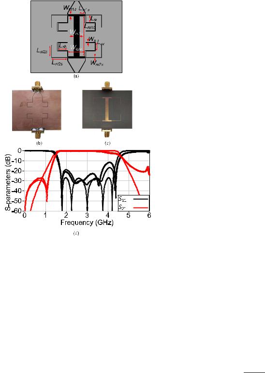
From these combinations, Z0e = 135 and Z0o = 100 operating points are chosen for practical implementation as it provides a good compromise between bandwidth and matching level. The three reflection zeros occur at 1.33, 1.5, and 2.47 GHz, and the 10-dB fractional bandwidth is 88.6%. Fig. 11(a) shows the layout of the proposed EC-SRR-loaded CPW unit cell, while Fig. 11(b) and (c) show the photograph of the fabricated structure. Meandered transmission lines are inserted at the four corners to elongate the inner loop and compensate for the difference in length between the inner and outer rings. Fig. 11(d) shows the corresponding EM simulations. The three reflection zeros occur at 1.27, 1.5, and 2.18 GHz and the 10-dB fractional bandwidth is 78.21%. The results are in good agreement with theory. Frequency shifts are because the circuit simulations do not account for the discontinuities and parasitic effects due to the layout, while the absence of the transmission zero is due to the same reason as in the SRR. Fig. 11(d) also shows the experimental results. They are in good agreement with EM simulations. Discrepancies between EM and measurements are due to fabrication tolerances.
Table II provides the comparison of the proposed designs and those in the literature. Comparison is limited to structures that were subject to the following two constraints: having SRRs at the bottom surface and operating at the balance
Fig. 11. Proposed EC-SRR-loaded CPW unit cell. (a) Layout. (b) and (c) Fabricated structure top and bottom surfaces, respectively. (d) S-parameters. Solid lines are EM simulations, dashed lines are circuit simulations, and dotted lines are measurements. Wcl = 0.5 mm, gcl = 0.85 mm, Wm = 0.5 mm,
gm = 0.25 mm, Ws = 0.4 mm, g = 0.5 mm, Lcl1 = 27.7 mm, Lcl2 = 5.5 mm, Ls1 = 4.9 mm, and Ls2 = 0.8 mm.
TABLE II
COMPARISON WITH BALANCED SRR-LOADED CPW UNIT CELLS
frequency. The proposed designs show the widest bandwidths with competitive sizes. Noting that the proposed methodology is frequency scalable and the electrical dimensions are predictable for any design frequency.
Authorized licensed use limited to: Newcastle University. Downloaded on May 16,2020 at 16:20:43 UTC from IEEE Xplore. Restrictions apply.

This article has been accepted for inclusion in a future issue of this journal. Content is final as presented, with the exception of pagination.
ELSHEIKH et al.: ANALYSIS AND DESIGN GUIDELINES FOR WIDEBAND CRLH SRR-LOADED CPW |
9 |
V. CONCLUSION
A wideband lumped-element model was proposed for CRLH SRR-loaded CPW. The model has three main advantages: all components have design equations. It provides closed-form expressions for the balanced condition. Finally, the proposed model is capable to explain the electrical behavior of the SRR and EC-SRR-loaded CPWs over a wide frequency range, whether in-band or out-of-band.
A new interpretation for these unit cells, which describes the CRLH SRR and EC-SRR-loaded CPWs as two slotline- to-MS transitions and two slotline-to-coupled MS line E-plane T-junctions, respectively, connected back-to-back, was also proposed. Both the lumped-element model and the proposed interpretation facilitated the development of design guidelines for wideband CRLH SRR and EC-SRR-loaded CPWs. Two designs were fabricated and characterized. Measurements, which are in good agreement with EM simulations, confirmed the theoretical predictions.
REFERENCES
[1]J. B. Pendry, A. J. Holden, D. J. Robbins, and W. J. Stewart, “Magnetism from conductors and enhanced nonlinear phenomena,” IEEE Trans. Microw. Theory Techn., vol. 47, no. 11, pp. 2075–2084, Nov. 1999.
[2]D. R. Smith and N. Kroll, “Negative refractive index in left-handed materials,” Phys. Rev. Lett., vol. 85, no. 14, pp. 2933–2936, Oct. 2000.
[3]F. Martın, J. Bonache, F. Falcone, M. Sorolla, and R. Marqués, “Split ring resonator-based left-handed coplanar waveguide,” Appl. Phys. Lett., vol. 83, no. 22, pp. 4652–4654, Dec. 2003.
[4]C. Caloz and T. Itoh, Electromagnetic Metamaterials: Transmission Line Theory and Microwave Applications. Hoboken, NJ, USA: Wiley, 2006.
[5]Á. Belenguer, J. Cascon, A. L. Borja, H. Esteban, and V. E. Boria, “Dual composite right-/left-handed coplanar waveguide transmission line using inductively connected split-ring resonators,” IEEE Trans. Microw. Theory Techn., vol. 60, no. 10, pp. 3035–3042, Oct. 2012.
[6] V. Sanz, A. Belenguer, L. Martinez, A. L. Borja, J. Cascon, and V. E. Boria, “Balanced right/left-handed coplanar waveguide with stubloaded split-ring resonators,” IEEE Antennas Wireless Propag. Lett., vol. 13, pp. 193–196, 2014.
[7]A. L. Borja, A. Belenguer, J. Cascon, H. Esteban, and V. E. Boria, “Wideband passband transmission line based on metamaterial-inspired CPW balanced cells,” IEEE Antennas Wireless Propag. Lett., vol. 10, pp. 1421–1424, 2011.
[8]A. Velez, F. Aznar, J. Bonache, M. C. Velazquez-Ahumada, J. Martel, and F. Martin, “Open complementary split ring resonators (OCSRRs) and their application to wideband CPW band pass filters,” IEEE Microw. Wireless Compon. Lett., vol. 19, no. 4, pp. 197–199, Apr. 2009.
[9]J. Selga, M. Gil, F. Aznar, J. Bonache, and F. Martin, “Composite right- /left-handed coplanar waveguides loaded with split ring resonators and their application to high-pass filters,” IET Microw., Antennas Propag., vol. 4, no. 7, pp. 822–827, 2010.
[10]G. Zamora, S. Zuffanelli, F. Paredes, F. J. Herraiz-Martinez, F. Martin, and J. Bonache, “Fundamental-mode leaky-wave antenna (LWA) using slotline and split-ring-resonator (SRR)-based metamaterials,” IEEE Antennas Wireless Propag. Lett., vol. 12, pp. 1424–1427, Oct. 2013.
[11]M. Alibakhshi-Kenari, R. A. Sadeghzadeh, and M. Naser-Moghadasi,
“Composite right–left-handed-based antenna with wide applications in very-high frequency–ultra-high frequency bands for radio transceivers,” IET Microw., Antennas Propag., vol. 9, no. 15, pp. 1713–1726, Dec. 2015.
[12]P. Velez, J. Munoz-Enano, K. Grenier, J. Mata-Contreras, D. Dubuc, and F. Martin, “Split ring resonator-based microwave fluidic sensors for electrolyte concentration measurements,” IEEE Sensors J., vol. 19, no. 7, pp. 2562–2569, Apr. 2019.
[13]J. Naqui, L. Su, J. Mata, and F. Martín, “Recent advances in the modeling of transmission lines loaded with split ring resonators,” Int. J. Antennas Propag., vol. 2015, pp. 1–13, Apr. 2015.
[14]F. Aznar, J. Bonache, and F. Martín, “Improved circuit model for lefthanded lines loaded with split ring resonators,” Appl. Phys. Lett., vol. 92, no. 4, Jan. 2008, Art. no. 043512.
[15] V. |
Sanz, A. Belenguer, A. L. Borja, |
J. Cascon, H. Esteban, and |
V. |
E. Boria, “Broadband equivalent |
circuit model for a coplanar |
waveguide line loaded with split ring resonators,” Int. J. Antennas Propag., vol. 2012, pp. 1–6, Oct. 2012.
[16]J. Naqui, M. Duran-Sindreu, and F. Martin, “Modeling split-ring resonator (SRR) and complementary split-ring resonator (CSRR) loaded transmission lines exhibiting cross-polarization effects,” IEEE Antennas Wireless Propag. Lett., vol. 12, pp. 178–181, Mar. 2013.
[17]M. A. G. Elsheikh and A. M. E. Safwat, “Geometrical modeling of striploaded CPW and its application to all CPW air-bridge free Wilkinson power dividers,” IEEE Trans. Microw. Theory Techn., vol. 67, no. 8,
pp.3370–3376, Aug. 2019.
[18]M. A. G. Elsheikh and A. M. E. Safwat, “Wideband modeling of SRR-loaded coplanar waveguide,” IEEE Trans. Microw. Theory Techn., vol. 67, no. 3, pp. 851–860, Mar. 2019.
[19]D. M. Pozar, Microwave Engineering. New York, NY, USA: Wiley, 1998.
[20]H. Wang, L. Zhu, and W. Menzel, “Ultra-wideband bandpass filter with hybrid microstrip/CPW structure,” IEEE Microw. Wireless Compon. Lett., vol. 15, no. 12, pp. 844–846, Dec. 2005.
[21]A. M. H. Nasr, A. M. E. Safwat, and H. Elhennawy, “Via-free microstrip to slotline Baluns using slotted microstrip cross-junction,” in Proc. 47th Eur. Microw. Conf. (EuMC), Nuremberg, Germany, Oct. 2017,
pp.85–88.
Mohamed A. G. Elsheikh (Graduate Student Member, IEEE) received the B.Sc. (Hons.) and M.Sc. degrees in electrical engineering from Ain Shams University, Cairo, Egypt, in 2016 and 2019, respectively. He is currently pursuing the Ph.D. degree at the Department of Electrical Engineering and Computer Science (EECS), Massachusetts Institute of Technology (MIT), Cambridge, MA, USA.
After his graduation, he was appointed as a Teaching/Research Assistant at the Electronics and Electrical Communications Department, Ain Shams
University, where he worked at the Microwaves and Antenna Research Lab. His research interests include passive and active microwave circuits, antennas, and novel electromagnetics materials and devices.
Nancy Y. Ammar received the B.Sc. degree (Hons.) in electronics and communication engineering from Ain Shams University, Cairo, Egypt, in 2019.
From her senior year, she worked as an Undergraduate Research Assistant with the Microwaves and Antenna Research Laboratory, Ain Shams University. She currently works as an IC Design Consultant at Mentor Graphics, Cairo. Her research interests include passive microwave circuits, optical micro-electro-mechanical systems (MEMSs), and integrated optics and lithography techniques.
Amr M. E. Safwat (Senior Member, IEEE) received the B.Sc. and M.Sc. degrees in electrical engineering from Ain Shams University, Cairo, Egypt, in 1993 and 1997, respectively, and the Ph.D. degree in electrical engineering from the University of Maryland, College Park, MD, USA, in 2001.
From 2001 to 2002, he was with Cascade Microtech Inc., Beaverton, OR, USA. In 2002, he joined the Electronics and Electrical Communication Engineering Department, Ain Shams University, where he is currently a Full Professor and
the Department Chair. He was also a Visiting Professor with Otto von Guericke University Magdeburg, Magdeburg, Germany, in 2004; the Institute National Polytechnique de Grenoble, Grenoble, France, in 2005; and the Radio Laboratory and MilliLab, University of Aalto, Espoo, Finland, from 2006 to 2007. His current research interests include metamaterial, microwave passive planar structures, and microwave photonics.
Dr. Safwat was a recipient of the Egyptian Encouragement State Prize for Engineering Sciences in 2007 and 2014 and the First Class Medal of Excellence from the President of Egypt in 2017.
Authorized licensed use limited to: Newcastle University. Downloaded on May 16,2020 at 16:20:43 UTC from IEEE Xplore. Restrictions apply.